EP0336308A2 - Verfahren und Vorrichtung für die automatische Frequenzregelung von Halbleiterlasern - Google Patents
Verfahren und Vorrichtung für die automatische Frequenzregelung von Halbleiterlasern Download PDFInfo
- Publication number
- EP0336308A2 EP0336308A2 EP89105665A EP89105665A EP0336308A2 EP 0336308 A2 EP0336308 A2 EP 0336308A2 EP 89105665 A EP89105665 A EP 89105665A EP 89105665 A EP89105665 A EP 89105665A EP 0336308 A2 EP0336308 A2 EP 0336308A2
- Authority
- EP
- European Patent Office
- Prior art keywords
- signal
- derivative
- laser
- ramp
- signals
- Prior art date
- Legal status (The legal status is an assumption and is not a legal conclusion. Google has not performed a legal analysis and makes no representation as to the accuracy of the status listed.)
- Granted
Links
Images


Classifications
-
- H—ELECTRICITY
- H04—ELECTRIC COMMUNICATION TECHNIQUE
- H04B—TRANSMISSION
- H04B10/00—Transmission systems employing electromagnetic waves other than radio-waves, e.g. infrared, visible or ultraviolet light, or employing corpuscular radiation, e.g. quantum communication
- H04B10/50—Transmitters
- H04B10/572—Wavelength control
-
- H—ELECTRICITY
- H01—ELECTRIC ELEMENTS
- H01S—DEVICES USING THE PROCESS OF LIGHT AMPLIFICATION BY STIMULATED EMISSION OF RADIATION [LASER] TO AMPLIFY OR GENERATE LIGHT; DEVICES USING STIMULATED EMISSION OF ELECTROMAGNETIC RADIATION IN WAVE RANGES OTHER THAN OPTICAL
- H01S5/00—Semiconductor lasers
- H01S5/06—Arrangements for controlling the laser output parameters, e.g. by operating on the active medium
- H01S5/068—Stabilisation of laser output parameters
- H01S5/0683—Stabilisation of laser output parameters by monitoring the optical output parameters
- H01S5/0687—Stabilising the frequency of the laser
-
- H—ELECTRICITY
- H04—ELECTRIC COMMUNICATION TECHNIQUE
- H04B—TRANSMISSION
- H04B10/00—Transmission systems employing electromagnetic waves other than radio-waves, e.g. infrared, visible or ultraviolet light, or employing corpuscular radiation, e.g. quantum communication
- H04B10/50—Transmitters
- H04B10/501—Structural aspects
- H04B10/506—Multiwavelength transmitters
-
- H—ELECTRICITY
- H01—ELECTRIC ELEMENTS
- H01S—DEVICES USING THE PROCESS OF LIGHT AMPLIFICATION BY STIMULATED EMISSION OF RADIATION [LASER] TO AMPLIFY OR GENERATE LIGHT; DEVICES USING STIMULATED EMISSION OF ELECTROMAGNETIC RADIATION IN WAVE RANGES OTHER THAN OPTICAL
- H01S5/00—Semiconductor lasers
- H01S5/40—Arrangement of two or more semiconductor lasers, not provided for in groups H01S5/02 - H01S5/30
- H01S5/4025—Array arrangements, e.g. constituted by discrete laser diodes or laser bar
Definitions
- the present invention refers to semiconductor lasers, and more particularly it concerns a method and a device for automatic frequency control of such lasers.
- a photomultiplier collects the beam emitted from the laser after such beam has been made to pass through a high stability Fabry-Perot interferometer, whose length is piezoelectrically modulated by a sinusoidal signal; a lock-in amplifier generates the first derivative of the interferometer spectrum by detecting the photomultiplier output signal synchronously with the modulating oscillation.
- a derivative becomes zero when the emission frequency is the nominal one, and is different from zero in the other cases.
- an error signal is obtained, which consists in the instant value of the derivative in its linear portion, and such a signal is used to control the laser temperature.
- this known system cannot be used to control a plurality of sources, as can be required in a multichannel transmission system: in effect, the technique adopted for generating the error signal, according to which a small frequency range about the maximum of the photomultiplier output peak is examined, does not allow the analysis of a sequence of peaks having the frequency spacing required by such systems.
- the beats are generated between the output signal of one of the lasers, stabilized in a conventional way and used as reference, and the signals emitted by the other lasers; the central beat frequencies are determined by a Fabry-Perot interferometer, and the information thus obtained is converted into digital electrical signals from which, after conversion into analog form, control signals for the other lasers are obtained.
- the known device is very complicated since it requires two stabilizing systems, one for the laser used as reference and the other for the remaining lasers; besides, since stabilization of said remaining lasers depends on that of the reference laser, the system performance depends on the reference stabilization precision.
- a method for the automatic frequency control of a semiconductor laser wherein a spectral analysis of the light signals emitted by the laser is effected, the signals representative of the spectrum are converted into electrical signals, the derivative of such electrical signals is generated, and an error signal is extracted from that derivative and is sent to laser driving devices, the method being characterized in that said spectral analysis is controlled by a ramp voltage signal, and in that: the zero crossing of the derivative within a ramp period is detected, said zero crossing identifying the actual emission frequency of the laser; the ramp signal is sampled in correspondence with the zero crossing of the derivative; and the sample obtained is algebraically summed with a reference signal dependent on the nominal emission frequency of the laser, the signal resulting from the algebraic sum forming said error signal.
- a method for the automatic frequency control of a light signal source comprising a plurality of semiconductor lasers whose emissions are frequency multiplexed, wherein a spectral analysis of the light signals emitted by the source is effected, the signals representative of the spectrum are converted into electrical signals, the derivative of such electrical signals is determined, and an error signal for each laser is obtained from the derivative and is sent to means driving the respective laser, the method being characterized in that said spectral analysis is controlled by a ramp voltage signal, and in that: the derivative zero crossings in a ramp period are detected, said zero crossings identifying each the actual emission frequency of one of the lasers; the ramp signal is sampled in correspondence with each zero crossing of the derivative; and each sample obtained is algebraically added to a respective reference signal dependent on the nominal emission frequency of the respective laser, the signals resulting from the algebraic sums forming said error signals.
- the device for carrying out the method of the first aspect of the invention comprises means for effecting the spectral analysis of the signals emitted by the source and for supplying electrical signals representative of the spectrum, means for calculating the derivative of said electrical signals and means for obtaining from said derivative an error signal for the laser, and is characterized in that the means for the spectral analysis is controlled by a ramp voltage signal generator; the derivative calculating means consists of a differentiating circuit; and the means for obtaining the error signal comprises: a circuit detecting the zero crossing of the derivative signal within a ramp signal period; a pulse generator generating a pulse in correspondence with the detection of the derivative zero crossing; means, controlled by said pulse generator, for sampling the ramp signal in correspondence with the derivative zero crossing; and means for algebraically summing the ramp signal sample and a reference signal dependent on the nominal emission frequency of the laser, the output signal of the summing means forming the error signal.
- the device for carrying out the method of the second aspect of the invention comprises means for effecting the spectral analysis of the signals emitted by the source and for supplying electrical signals representative of the spectrum, means for calculating the derivative of said electrical signals and means for obtaining from said derivative an error signal for each laser, and is characterized in that the means for the spectral analysis is controlled by a ramp voltage signal generator; the derivative calculating means consists of a differentiating circuit; and the means for obtaining the error signal comprises a circuit detecting the zero crossings of the derivative in a period of the ramp signal; a pulse generator generating a pulse in correspondence with the detection of each zero crossing of the derivative, each pulse being relative to one of the lasers; a plurality of samplers, controlled by said pulse generator, each of which is associated with one of the lasers and samples the ramp signal in correspondence with the zero crossing of the derivative corresponding to the emission frequency of the associated laser; and a plurality of adding circuits, each connected to one of the sample-and-hold circuits, for algebraically
- Fig. 1 shows the device according to the invention used to adjust the injection current of a semiconductor laser 1 used as a signal source in an optical communications system, of which only modulator 2 and optical fibre transmission line 2′ are shown.
- Laser 1 is e.g. a distributed feedback laser: said lasers are particularly suitable for use in coherent communications systems, thanks to their linewidth characteristics.
- the usual temperature control devices are incorporated into block 1; reference numeral 3 denotes the injection current source.
- the optical signal emitted by laser 1 is sent, through an optical system schematized by beam splitter 4 and mirror 5, towards both modulator 2 and the control device, generally shown at 100.
- the beam directed to control device 100 is sent to a frequency discriminator or spectrum analyser, consisting of a Fabry-Perot scanning interferometer 6, through an optical insulator 7, an attenuator 8, and a possible focusing optical system, schematized by lens 9.
- the distance between the mirrors of interferometer 6 is modified by a piezoelectric device 10 fed by a ramp voltage, supplied by generator 11.
- interferometer resonance frequency linearly depends on the voltage applied.
- the ramp will advantageously have such characteristics as to cause an interferometer length variation up to the so called free spectral range of the interferometer.
- a detector 12 converts the optical signals into electrical signals and supplies them, through amplifier 13, to a differentiating circuit 14 which calculates the derivative thereof.
- Comparator 15 detects the zero crossing point of the derivative signal, which point identifies the actual central emission frequency of the laser, and emits a signal indicating such detection.
- Such a signal is converted by pulse generator 16 into a short pulse which is applied to a control input of a sample-and-hold circuit 17, receiving also the ramp signal emitted by generator 11, duly attenuated.
- the ramp signal is thus sampled in correspondence with the zero crossing of the interferometer spectrum derivative.
- the samples emitted from circuit 17 are filtered in a low-pass filter 18, with time constant much longer than the sampling period of sample-and-hold circuit 17, and are compared in a differential amplifier 19 with a reference signal VR dependent on the nominal oscillation frequency of the laser.
- the signal outgoing from amplifier 19 is the error signal which is supplied to injection current source 3 to change the current so as to compensate the emission frequency fluctuations.
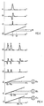
- Fig. 2 shows the shape of some signals of interest within a ramp signal period: curve a) is the signal outgoing from detector 12; curve b) is the derivative of signal a); c) is the sampling pulse; lastly sketch d) shows the generation of the ramp signal sample (denoted by 17) and of the error signal, denoted by 19, as a result of the comparison with reference signal VR.
- the circuit according to the invention eliminates the drawbacks of the prior art: more particularly, recognition of the derivative zero crossing in order to identify the central laser frequency renders the system performance independent of linewidth and power, which affect the derivative slope; no expensive apparatus is required, since the derivative is obtained by a simple differentiating circuit; lastly, by a suitable choice of the ramp characteristics, the interferometer can carry out a scanning whose amplitude reaches the so-called free spectral range.
- Fig. 3 shows an embodiment of the invention for the automatic frequency control of a plurality of lasers 1a, 1b ... 1n, each having its own emission frequency established by the corresponding injection current source 3a, 3b...3n.
- the signals emitted by lasers 1a, 1b...1n are sent to a coupler 20 generating a single beam used in a frequency division optical communications system (not shown).
- the control device is denoted as a whole by 200 and the devices present also in the embodiment of Fig. 1 are denoted by the same references.
- the elements upstream interferometer 6 have not been represented.
- interferometer 6 is modulated by ramp generator 11 through piezoelectric device 10, and is followed by detector 12, amplifier 13, differentiating circuit 14, comparator 15 and pulse generator 16. Yet in this case, since the beam sent to interferometer 6 comprises a plurality of frequencies, the signal outgoing from detector 12 will present, within a ramp signal period, a sequence of peaks (Fig. 4a), each corresponding to the spectral line of one of lasers 1a, 1b...1n. Similarly, the output signal of differentiating circuit 14 will comprise a sequence of waveforms (Fig. 4b) similar to that of Fig. 2b. Comparator 15 will supply a signal indicative of the zero crossing of each of the waveforms of Fig.
- pulse generator 16 will supply a pulse (Fig. 4c) at each leading edge of the signal outgoing from comparator 15. Obviously, care must be taken that the signal emitted by the comparator has basically the same duration as the derivative of each peak, to avoid the emission of spurious pulses in correspondence with the return to 0 of the waveforms of Fig. 4b.
- Pulse generator 16 is connected to a counter 21, counting the pulses emitted by generator 16, and to a demultiplexer 22, receiving as control signal the output signal of counter 21.
- Demultiplexer 22 has n outputs connected each to a corresponding sample-and-hold circuit 17a, 17b...17n and, depending on the count of counter 21, transfers onto one of such outputs the pulse present at its input. E.g., supposing that peaks A, B,...N in Fig.
- the first pulse emitted by generator 16 will be supplied to sample-and-hold circuit 17a as a sampling pulse, the second to circuit 17b, and so on until the last pulse, which will be supplied to circuit 17n.
- Circuits 17a, 17b...17n are all connected to ramp generator 11 and they sample the ramp at the instant indicated by the corresponding sampling pulse.
- each sample is filtered in a respective low pass filter 18a, 18b...18n and compared, in differential amplifier 19a, 19b...19n, with respective reference voltage VRa, VRb...VRn.
- the error signals (Figs. 4d, 4e, 4f) to be applied to injection current sources 3a, 3b...3n of the individual lasers are thus obtained.
- the embodiment of the invention employed to control a plurality of sources has the advantages described in connection with Fig. 1 as to operation flexibility, performance and electronic circuit simplicity.
- the lasers are controlled independently of one another, so that the system performance does not depend on the good stabilization of one of them, taken as a reference; finally, it is not required to use two stabilization circuits of different type each demanding its frequency discriminator.
Landscapes
- Physics & Mathematics (AREA)
- Electromagnetism (AREA)
- Engineering & Computer Science (AREA)
- Computer Networks & Wireless Communication (AREA)
- Signal Processing (AREA)
- Condensed Matter Physics & Semiconductors (AREA)
- General Physics & Mathematics (AREA)
- Optics & Photonics (AREA)
- Semiconductor Lasers (AREA)
Applications Claiming Priority (2)
| Application Number | Priority Date | Filing Date | Title |
|---|---|---|---|
| IT6728888 | 1988-03-31 | ||
| IT8867288A IT1219165B (it) | 1988-03-31 | 1988-03-31 | Procedimento e dispositivo per il controllo automatico di frequenza di laser a semiconduttore |
Publications (3)
| Publication Number | Publication Date |
|---|---|
| EP0336308A2 true EP0336308A2 (de) | 1989-10-11 |
| EP0336308A3 EP0336308A3 (de) | 1991-02-27 |
| EP0336308B1 EP0336308B1 (de) | 1993-10-13 |
Family
ID=11301172
Family Applications (1)
| Application Number | Title | Priority Date | Filing Date |
|---|---|---|---|
| EP89105665A Expired - Lifetime EP0336308B1 (de) | 1988-03-31 | 1989-03-30 | Verfahren und Vorrichtung für die automatische Frequenzregelung von Halbleiterlasern |
Country Status (6)
| Country | Link |
|---|---|
| US (1) | US4918700A (de) |
| EP (1) | EP0336308B1 (de) |
| JP (1) | JPH067615B2 (de) |
| CA (1) | CA1281367C (de) |
| DE (2) | DE336308T1 (de) |
| IT (1) | IT1219165B (de) |
Cited By (5)
| Publication number | Priority date | Publication date | Assignee | Title |
|---|---|---|---|---|
| EP0481242A3 (de) * | 1990-09-20 | 1992-05-06 | Fujitsu Limited | Vorrichtung zur Steuerung und Messung der optischen Frequenztastung von Laserlicht |
| EP0618653A3 (de) * | 1993-03-30 | 1995-04-12 | Nippon Electric Co | Frequenzstabilisationsverfahren für Halbleiterlaser, frequenzstabilisierte Lichtquelle und Lasermodul. |
| EP0746068A1 (de) * | 1993-05-31 | 1996-12-04 | Nec Corporation | Frequenzstabilisationsverfahren für Halbleiterlaser, frequenzstabilisierte Lichtquelle und Lasermodul |
| EP0703679A3 (de) * | 1994-09-26 | 1999-12-15 | Nippon Telegraph And Telephone Corporation | Schaltung zur gleichzeitiger Überwachung mehrerer Wellenlängen unter Verwendung eines aus gruppierten Wellenleiter gebautes Gitters |
| EP0874490A3 (de) * | 1997-04-25 | 2000-04-19 | Nec Corporation | Optische Übertragungseinrichtung |
Families Citing this family (9)
| Publication number | Priority date | Publication date | Assignee | Title |
|---|---|---|---|---|
| GB2231713B (en) * | 1989-03-30 | 1994-03-23 | Toshiba Kk | Semiconductor laser apparatus |
| JPH0783265B2 (ja) * | 1989-08-21 | 1995-09-06 | 新技術事業団 | レーザ励起ルビジウム原子発振器 |
| JP2839611B2 (ja) * | 1990-01-16 | 1998-12-16 | 沖電気工業株式会社 | 自動周波数制御回路 |
| US5111468A (en) * | 1990-10-15 | 1992-05-05 | International Business Machines Corporation | Diode laser frequency doubling using nonlinear crystal resonator with electronic resonance locking |
| JP3235738B2 (ja) * | 1992-05-20 | 2001-12-04 | 株式会社トプコン | アブソリュート測長器 |
| JP2772605B2 (ja) * | 1992-10-15 | 1998-07-02 | 国際電信電話株式会社 | 光周波数多重キャリヤ制御装置 |
| US7418015B2 (en) * | 2004-02-23 | 2008-08-26 | Finisar Corporation | System and method for control of optical transmitter |
| ATE378580T1 (de) * | 2004-03-09 | 2007-11-15 | Senscient Ltd | Gasnachweis |
| US20120008653A1 (en) * | 2010-07-09 | 2012-01-12 | Ipg Photonics Corporation | Laser System with Dynamically Stabilized Transient Wavelength and Method of Operating Same |
Family Cites Families (7)
| Publication number | Priority date | Publication date | Assignee | Title |
|---|---|---|---|---|
| JPS5852891A (ja) * | 1981-09-24 | 1983-03-29 | Japan Radio Co Ltd | レ−ザの周波数安定化装置 |
| JPS6035588A (ja) * | 1983-08-08 | 1985-02-23 | Norito Suzuki | 周波数安定化レ−ザ−装置 |
| US4583228A (en) * | 1983-11-21 | 1986-04-15 | At&T Bell Laboratories | Frequency stabilization of lasers |
| JPH0627913B2 (ja) * | 1984-12-21 | 1994-04-13 | ソニー株式会社 | 光変調装置 |
| JPS6343385A (ja) * | 1986-08-08 | 1988-02-24 | Olympus Optical Co Ltd | レ−ザの高周波重畳自動出力制御装置 |
| JPS6344783A (ja) * | 1986-08-12 | 1988-02-25 | Fujitsu Ltd | レ−ザ光源の周波数安定化装置 |
| JPS63193583A (ja) * | 1987-02-06 | 1988-08-10 | Ando Electric Co Ltd | レ−ザダイオ−ドの矩形波変調回路 |
-
1988
- 1988-03-31 IT IT8867288A patent/IT1219165B/it active
-
1989
- 1989-03-08 JP JP1053980A patent/JPH067615B2/ja not_active Expired - Lifetime
- 1989-03-17 CA CA000594128A patent/CA1281367C/en not_active Expired - Lifetime
- 1989-03-24 US US07/328,439 patent/US4918700A/en not_active Expired - Lifetime
- 1989-03-30 DE DE198989105665T patent/DE336308T1/de active Pending
- 1989-03-30 DE DE89105665T patent/DE68909824T2/de not_active Expired - Fee Related
- 1989-03-30 EP EP89105665A patent/EP0336308B1/de not_active Expired - Lifetime
Cited By (6)
| Publication number | Priority date | Publication date | Assignee | Title |
|---|---|---|---|---|
| EP0481242A3 (de) * | 1990-09-20 | 1992-05-06 | Fujitsu Limited | Vorrichtung zur Steuerung und Messung der optischen Frequenztastung von Laserlicht |
| EP0618653A3 (de) * | 1993-03-30 | 1995-04-12 | Nippon Electric Co | Frequenzstabilisationsverfahren für Halbleiterlaser, frequenzstabilisierte Lichtquelle und Lasermodul. |
| EP0746068A1 (de) * | 1993-05-31 | 1996-12-04 | Nec Corporation | Frequenzstabilisationsverfahren für Halbleiterlaser, frequenzstabilisierte Lichtquelle und Lasermodul |
| EP0703679A3 (de) * | 1994-09-26 | 1999-12-15 | Nippon Telegraph And Telephone Corporation | Schaltung zur gleichzeitiger Überwachung mehrerer Wellenlängen unter Verwendung eines aus gruppierten Wellenleiter gebautes Gitters |
| EP0874490A3 (de) * | 1997-04-25 | 2000-04-19 | Nec Corporation | Optische Übertragungseinrichtung |
| US6215572B1 (en) | 1997-04-25 | 2001-04-10 | Nec Corporation | Wavelength division multiplexing optical transmission apparatus |
Also Published As
| Publication number | Publication date |
|---|---|
| CA1281367C (en) | 1991-03-12 |
| EP0336308A3 (de) | 1991-02-27 |
| IT1219165B (it) | 1990-05-03 |
| US4918700A (en) | 1990-04-17 |
| IT8867288A0 (it) | 1988-03-31 |
| JPH067615B2 (ja) | 1994-01-26 |
| DE68909824T2 (de) | 1994-03-10 |
| EP0336308B1 (de) | 1993-10-13 |
| DE68909824D1 (de) | 1993-11-18 |
| JPH01276786A (ja) | 1989-11-07 |
| DE336308T1 (de) | 1991-06-13 |
Similar Documents
| Publication | Publication Date | Title |
|---|---|---|
| EP0336308B1 (de) | Verfahren und Vorrichtung für die automatische Frequenzregelung von Halbleiterlasern | |
| EP0240512B1 (de) | Frequenzreferenzsystem und -methode | |
| US20050078317A1 (en) | Synchronizing the filter wavelength of an optical filter with the wavelength of a swept local oscillator signal | |
| EP0703679A2 (de) | Schaltung zur gleichzeitiger Überwachung mehrerer Wellenlängen unter Verwendung eines aus gruppierten Wellenleiter gebautes Gitters | |
| JPH079386B2 (ja) | 光ファイバ分散特性測定方式 | |
| US4344173A (en) | Stabilization circuit for a digitally operated laser | |
| US5390017A (en) | Optical network analyzer for measuring the amplitude characteristics and group delay time dispersion characteristics of an optical circuit device | |
| US6738187B2 (en) | Semiconductor optical amplifiers using wavelength locked loop tuning and equalization | |
| EP0303293A2 (de) | Verfahren zur Modulation und Feststellung der Temperatur eines Lasers | |
| US6674065B2 (en) | Method and system for linearization of MOEMS tunable filter scan | |
| US6885462B2 (en) | Wavelength monitoring device and method of tunable laser sources | |
| JPH06101604B2 (ja) | 複数の光源周波数の安定化方法 | |
| EP0614074B1 (de) | Gerät zur messung der optischen wellenlänge | |
| JPH0882554A (ja) | 波長監視装置 | |
| US5367396A (en) | Optical frequency marking method and different frequency channel communication network using it | |
| US20070024855A1 (en) | Optical frequency measurement apparatus and optical frequency measurement method | |
| US5081710A (en) | Laser transmitter | |
| JPH0897775A (ja) | 波長監視装置 | |
| US6765938B2 (en) | System for controlling wavelength of laser beam | |
| WO2019143136A1 (ko) | 위상잡음 보상에 의한 좁은 선폭 레이저 광원 구현장치 및 방법 | |
| JP2868041B2 (ja) | 光周波数間隔安定化装置 | |
| JP2000284192A (ja) | 光周波数グリッド発生装置 | |
| JP3317025B2 (ja) | 光周波数分割多重伝送装置 | |
| Miyazaki et al. | Frequency stabilization of FDM optical signals using an electronic counter | |
| JP2635824B2 (ja) | 光波長測定器 |
Legal Events
| Date | Code | Title | Description |
|---|---|---|---|
| PUAI | Public reference made under article 153(3) epc to a published international application that has entered the european phase |
Free format text: ORIGINAL CODE: 0009012 |
|
| AK | Designated contracting states |
Kind code of ref document: A2 Designated state(s): DE FR GB NL SE |
|
| PUAL | Search report despatched |
Free format text: ORIGINAL CODE: 0009013 |
|
| AK | Designated contracting states |
Kind code of ref document: A3 Designated state(s): DE FR GB NL SE |
|
| EL | Fr: translation of claims filed | ||
| 17P | Request for examination filed |
Effective date: 19910228 |
|
| TCNL | Nl: translation of patent claims filed | ||
| DET | De: translation of patent claims | ||
| 17Q | First examination report despatched |
Effective date: 19921130 |
|
| GRAA | (expected) grant |
Free format text: ORIGINAL CODE: 0009210 |
|
| AK | Designated contracting states |
Kind code of ref document: B1 Designated state(s): DE FR GB NL SE |
|
| REF | Corresponds to: |
Ref document number: 68909824 Country of ref document: DE Date of ref document: 19931118 |
|
| ET | Fr: translation filed | ||
| PLBE | No opposition filed within time limit |
Free format text: ORIGINAL CODE: 0009261 |
|
| STAA | Information on the status of an ep patent application or granted ep patent |
Free format text: STATUS: NO OPPOSITION FILED WITHIN TIME LIMIT |
|
| 26N | No opposition filed | ||
| EAL | Se: european patent in force in sweden |
Ref document number: 89105665.7 |
|
| NLS | Nl: assignments of ep-patents |
Owner name: OTC-OPTICAL TECHNOLOGIES CENTER S.R.L. |
|
| REG | Reference to a national code |
Ref country code: GB Ref legal event code: 732E |
|
| REG | Reference to a national code |
Ref country code: FR Ref legal event code: TP |
|
| PGFP | Annual fee paid to national office [announced via postgrant information from national office to epo] |
Ref country code: SE Payment date: 20010306 Year of fee payment: 13 |
|
| PGFP | Annual fee paid to national office [announced via postgrant information from national office to epo] |
Ref country code: NL Payment date: 20010307 Year of fee payment: 13 Ref country code: DE Payment date: 20010307 Year of fee payment: 13 |
|
| REG | Reference to a national code |
Ref country code: GB Ref legal event code: 732E |
|
| NLS | Nl: assignments of ep-patents |
Owner name: AGILENT TECHNOLOGIES, INC |
|
| REG | Reference to a national code |
Ref country code: FR Ref legal event code: TP |
|
| REG | Reference to a national code |
Ref country code: GB Ref legal event code: IF02 |
|
| PGFP | Annual fee paid to national office [announced via postgrant information from national office to epo] |
Ref country code: FR Payment date: 20020304 Year of fee payment: 14 |
|
| PG25 | Lapsed in a contracting state [announced via postgrant information from national office to epo] |
Ref country code: SE Free format text: LAPSE BECAUSE OF NON-PAYMENT OF DUE FEES Effective date: 20020331 |
|
| PG25 | Lapsed in a contracting state [announced via postgrant information from national office to epo] |
Ref country code: DE Free format text: LAPSE BECAUSE OF NON-PAYMENT OF DUE FEES Effective date: 20021001 Ref country code: NL Free format text: LAPSE BECAUSE OF NON-PAYMENT OF DUE FEES Effective date: 20021001 |
|
| EUG | Se: european patent has lapsed |
Ref document number: 89105665.7 |
|
| NLV4 | Nl: lapsed or anulled due to non-payment of the annual fee |
Effective date: 20021001 |
|
| PG25 | Lapsed in a contracting state [announced via postgrant information from national office to epo] |
Ref country code: FR Free format text: LAPSE BECAUSE OF NON-PAYMENT OF DUE FEES Effective date: 20031127 |
|
| REG | Reference to a national code |
Ref country code: FR Ref legal event code: ST |
|
| PGFP | Annual fee paid to national office [announced via postgrant information from national office to epo] |
Ref country code: GB Payment date: 20060329 Year of fee payment: 18 |
|
| REG | Reference to a national code |
Ref country code: GB Ref legal event code: 732E |
|
| GBPC | Gb: european patent ceased through non-payment of renewal fee |
Effective date: 20070330 |
|
| PG25 | Lapsed in a contracting state [announced via postgrant information from national office to epo] |
Ref country code: GB Free format text: LAPSE BECAUSE OF NON-PAYMENT OF DUE FEES Effective date: 20070330 |