EP0336590B1 - Assemblage de roue de renvoi pour véhicule à chenille - Google Patents
Assemblage de roue de renvoi pour véhicule à chenille Download PDFInfo
- Publication number
- EP0336590B1 EP0336590B1 EP89302651A EP89302651A EP0336590B1 EP 0336590 B1 EP0336590 B1 EP 0336590B1 EP 89302651 A EP89302651 A EP 89302651A EP 89302651 A EP89302651 A EP 89302651A EP 0336590 B1 EP0336590 B1 EP 0336590B1
- Authority
- EP
- European Patent Office
- Prior art keywords
- wear
- assembly according
- segments
- hub
- clamping members
- Prior art date
- Legal status (The legal status is an assumption and is not a legal conclusion. Google has not performed a legal analysis and makes no representation as to the accuracy of the status listed.)
- Expired
Links
- 244000043261 Hevea brasiliensis Species 0.000 claims description 2
- 229920003052 natural elastomer Polymers 0.000 claims description 2
- 229920001194 natural rubber Polymers 0.000 claims description 2
- 230000000149 penetrating effect Effects 0.000 claims 1
- 230000000712 assembly Effects 0.000 description 8
- 238000000429 assembly Methods 0.000 description 8
- 239000002184 metal Substances 0.000 description 8
- 238000010276 construction Methods 0.000 description 2
- 229920001971 elastomer Polymers 0.000 description 2
- 239000013536 elastomeric material Substances 0.000 description 2
- 230000013011 mating Effects 0.000 description 2
- 230000006866 deterioration Effects 0.000 description 1
- 230000003993 interaction Effects 0.000 description 1
- 230000002035 prolonged effect Effects 0.000 description 1
Images

Classifications
-
- B—PERFORMING OPERATIONS; TRANSPORTING
- B62—LAND VEHICLES FOR TRAVELLING OTHERWISE THAN ON RAILS
- B62D—MOTOR VEHICLES; TRAILERS
- B62D55/00—Endless track vehicles
- B62D55/08—Endless track units; Parts thereof
- B62D55/14—Arrangement, location, or adaptation of rollers
- B62D55/145—Rollers with replaceable wear rings or rims
Definitions
- This invention relates to an idler wheel assembly for a vehicle and having a plurality of individual replaceable wear segments which cooperate to form a continuous tread surface with the wear segments being resiliently isolated from a hub of the idler wheel.
- Earthmoving and construction vehicles which utilize self-laying endless track chain assemblies for support and propulsion generally include one or more idler wheels for guiding and supporting portions of the track chain. Since the track chains include metal connecting links, which contact metal tread portions of the idler wheel during the track guiding function, considerable noise and vibration is generated by the metal to metal contact of the moving components.
- an idler wheel assembly for a track-laying vehicle comprises a circular hub having first and second side portions and a circumferential surface portion, the surface portion having a central support surface, first and second contact surfaces, and first and second U-shaped circumferential grooves, each positioned between a respective one of the contact surfaces and the central support surface; a plurality of first wear segments positioned within the first groove, and a plurality of second wear segments positioned within the second groove; resilient means located within the grooves and positioned between the hub and the wear segments; a plurality of clamping members, the clamping members encircling the hub, contacting the wear segments and compressing the resilient means; and means for securing the clamping members to the central support surface of the hub.
- Track-laying vehicles generate considerably noise and vibration from the interaction of various moving track components. Some of these components are the track idler wheel and the track links which are guided and supported by the idler wheel. The noise is irritating to the machine operator, other workers in close proximity, and anyone else who is close to the work site.
- the subject invention provides a reduced noise level wheel assembly by isolating the idler wheel treads from the wheel hub with resilient rings. The invention also reduces impact forces so noise radiating from the track is less.
- a track-laying vehicle 10 includes an engine 12, an operator's station 14, a main frame 16, a powered sprocket 18, and front and rear idler wheel assemblies 20 and 22.
- the main frame 16 supports a subframe 24, which in turn supports the idler wheel assemblies 20 and 22, as well as a plurality of guide roller assemblies 26.
- An endless track 28 is driven by the sprocket 18 and encircles the idler wheel assemblies 20,22 and the roller assemblies 26.
- the idler wheel assemblies 20 and 22 are substantially similar and, therefore, only the front idler assembly 20 will be described in detail.
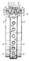
- the idler wheel assembly 20, which supports and guides the endless track includes a circular hub or body 30, which has first and second side portions 32 and 34, a central circumferential support surface portion 36, and first and second circumferential contact, or clamping, surfaces 38 and 40.
- the wheel assembly 20 further includes first and second circumferential "U" shaped grooves or cavities 42 and 44, with one cavity positioned between each of the contact surfaces 38,40 and the central support surface 36.
- First and second formed resilient rings 46 and 48 are located within the first and second cavities 42 and 44 respectively.
- the rings 46 and 48 are preferably formed of natural rubber and have a pre-formed shape which conforms substantially to the shape of the first and second cavities 42 and 44.
- the ring 46 is held within the cavity 42 by a plurality of hardened metal wear segments 50, and the ring 48 is held within the cavity 44 by a plurality of similar hardened metal wear segments 52.
- a plurality of arcuate shaped clamping plates 54 encircle the hub 30 and contact the wear segments 50 and 52.
- the clamping plates 54 are secured to the hub by a plurality of threaded fasteners 56 which penetrate through bores 58 in each plate 54 and engage threaded apertures 60 in the hub surface 36. As the fasteners 56 are tightly engaged with the apertures 60, the plates 54 engage the wear segments 50 and 52 and these segments compress the rubber rings 46 and 48 between the segments 50,52 and the hub cavities 42 and 44.
- Each of the wear segments 50,52 has a cross-sectional configuration which is substantially similar to the combined cross-sectional configuration of one of the cavities 42,44 and one of the adjacent contact surfaces 38,40.
- each of the clamping plates 54 overlaps a portion of one of the wear segments 50 and a portion of one of the wear segments 52.
- the wear surfaces 62,64 of the wear segments 50,52 have an arcuate shape.
- the external surfaces of the clamping plates 54 also have an arcuate shape.
- the arcuate angle of the wear segments 50,52 and the clamping plates is approximately 45°.
- the subject idler wheel assembly 20 is particularly useful with earthmoving and construction vehicles and specifically, track-laying vehicles, such as the vehicle 10. Power from the engine 12 is transmitted to the sprocket 18 which rotates and drives the endless track 28. The track 28 travels around the idlers 20 and 22 and the guide roller assemblies 26.
- the metal track 28 contacts the metal wear segments 50,52, noise and vibration are generated. Because the segments 50,52 are isolated from the wheel hub 30 by the resilient rings 46,48, the noise and vibration are not transferred into the wheel hub 30, where is could be amplified. Because the noise level produced by contact between the idler wheel assembly 20 and the track 28 is lower, the vehicle can operate closer to workers and occupied buildings without being objectionable. Also, because the vibrations are damped, the life of the track 28 and vehicle components are prolonged.
Landscapes
- Engineering & Computer Science (AREA)
- Chemical & Material Sciences (AREA)
- Combustion & Propulsion (AREA)
- Transportation (AREA)
- Mechanical Engineering (AREA)
- Gears, Cams (AREA)
- Tires In General (AREA)
- Arrangement And Driving Of Transmission Devices (AREA)
Claims (10)
- Ensemble formant roue de renvoi (20) pour un véhicule reposant sur des chenilles (10), l'ensemble comprenant un moyeu circulaire (30) présentant des première et seconde parties latérales (32, 34) et une partie de surface circonférentielle, la partie de surface présentant une surface de support centrale (36), des première et seconde surfaces de contact (38, 40), et des première et seconde rainures circonférentielles en U (42, 44), chacune étant positionnée entre une surface correspondante des surfaces de contact (38, 40) et la surface de support centrale (36); une multiplicité de premiers segments d'usure (50) positionnés à l'intérieur de la première rainure (42), et une multiplicité de seconds segments d'usure (52) positionnés à l'intérieur de la seconde rainure (44); des moyens élastiques (46, 48) situés à l'intérieur des rainures (42, 44) et positionnés entre le moyeu (30) et les segments d'usure (50, 52); une multiplicité d'éléments de serrage (54), les éléments de serrage (54) encerclant le moyeu (30), venant au contact des segments d'usure (50, 52) et comprimant les moyens élastiques (46, 48); et des moyens (56, 60) pour assujettir les éléments de serrage (54) à la surface de support centrale (36) du moyeu (30).
- Ensemble selon la revendication 1, dans lequel les moyens élastiques comprennent des premier et second éléments formant anneaux (46, 48) présentant une configuration préformée qui épouse sensiblement la forme des première et seconde rainures en U (42, 44) et des première et seconde surfaces de contact (38, 40) respectivement.
- Ensemble selon la revendication 1 ou la revendication 2, dans lequel chacun des segments d'usure (50, 52) présente une configuration de section transversale qui est sensiblement similaire à la configuration de section transversale combinée d'une rainure correspondante des rainures (42, 44) et des surfaces de contact adjacentes (38, 40).
- Ensemble selon l'une quelconque des revendications précédentes, dans lequel chacun des éléments de serrage (54) chevauche une partie d'un premier segment d'usure (50) et une partie d'un second segment d'usure (52).
- Ensemble selon l'une quelconque des revendications précédentes, dans lequel la multiplicité de premiers segments d'usure (50) forme une première surface de roulement circulaire continue (62) et la multiplicité de seconds segments d'usure (52) forme une seconde surface de roulement circulaire continue (64).
- Ensemble selon l'une quelconque des revendications précédentes, dans lequel chacun des éléments de serrage (54) présente une multiplicité d'alésages traversants (58) et les moyens d'assujettissement (56, 60) comprennent une multiplicité d'ouvertures filetées (60) dans la surface de support centrale (36) et une multiplicité de moyens de fixation filetés (56), les moyens de fixation (56) pénétrant dans les alésages traversants (58) et s'engageant dans les ouvertures (60).
- Ensemble selon l'une quelconque des revendications précédentes, dans lequel les moyens élastiques (46, 48) comprennent des premier et second anneaux (46, 48) en caoutchouc naturel.
- Ensemble selon l'une quelconque des revendications précédentes, dans lequel chacun des éléments de serrage (54) présente une partie de surface externe arquée délimitée par un angle de sensiblement 45°.
- Ensemble selon l'une quelconque des revendications précédentes, dans lequel chacun des premiers et seconds segments d'usure (50, 52) comprend une surface d'usure durcie (62, 64).
- Ensemble selon la revendication 9, dans lequel la surface d'usure (62, 64) de chaque segment d'usure (50, 52) présente une forme arquée délimitée par un angle de sensiblement 45°.
Applications Claiming Priority (2)
| Application Number | Priority Date | Filing Date | Title |
|---|---|---|---|
| US07/177,275 US4818041A (en) | 1988-04-04 | 1988-04-04 | Idler wheel assembly for track-type vehicle |
| US177275 | 1988-04-04 |
Publications (3)
| Publication Number | Publication Date |
|---|---|
| EP0336590A2 EP0336590A2 (fr) | 1989-10-11 |
| EP0336590A3 EP0336590A3 (en) | 1990-05-02 |
| EP0336590B1 true EP0336590B1 (fr) | 1992-09-09 |
Family
ID=22647945
Family Applications (1)
| Application Number | Title | Priority Date | Filing Date |
|---|---|---|---|
| EP89302651A Expired EP0336590B1 (fr) | 1988-04-04 | 1989-03-17 | Assemblage de roue de renvoi pour véhicule à chenille |
Country Status (5)
| Country | Link |
|---|---|
| US (1) | US4818041A (fr) |
| EP (1) | EP0336590B1 (fr) |
| JP (1) | JP2683273B2 (fr) |
| CA (1) | CA1296374C (fr) |
| DE (1) | DE68902760T2 (fr) |
Families Citing this family (46)
| Publication number | Priority date | Publication date | Assignee | Title |
|---|---|---|---|---|
| US5040855A (en) * | 1990-08-31 | 1991-08-20 | Caterpillar Inc. | Isolated rim roller assembly |
| CA2062549C (fr) * | 1991-05-07 | 1995-11-07 | Robert Willis Brittain | Roue motrice pour tracteur sur chenilles |
| JP3262990B2 (ja) * | 1996-06-25 | 2002-03-04 | 本田技研工業株式会社 | クローラベルト装置 |
| US6012784A (en) * | 1998-01-30 | 2000-01-11 | Caterpillar Inc. | Impact reducing idler wheel for a track-driven machine |
| US6280009B1 (en) | 1999-12-03 | 2001-08-28 | Caterpillar Inc. | Sound reducing carrier roller |
| US6652043B2 (en) * | 2000-04-20 | 2003-11-25 | Caterpillar Inc | Reduced sound transmitting idler for track-type vehicles |
| US6416142B1 (en) * | 2000-04-20 | 2002-07-09 | Caterpillar Inc. | Reduced sound transmitting idler for track-type vehicles |
| US6631961B1 (en) * | 2001-08-27 | 2003-10-14 | Caterpillar Inc | Isolated rim idler |
| US6739678B2 (en) | 2002-07-23 | 2004-05-25 | Caterpillar Inc | Isolated idler assembly |
| US6733093B2 (en) * | 2002-07-25 | 2004-05-11 | Soucy International Inc. | Split wheel and method for installing endless track |
| US6899651B2 (en) | 2002-09-17 | 2005-05-31 | Caterpillar Inc | Reduced sound transmitting sprocket |
| US7198337B2 (en) * | 2003-01-23 | 2007-04-03 | Kinze Manufacturing, Inc. | Wheel for belted track vehicles |
| CA2457999A1 (fr) | 2004-02-17 | 2005-08-17 | Michel Paradis | Roues de guidage de chenille |
| US7390740B2 (en) * | 2004-09-02 | 2008-06-24 | Micron Technology, Inc. | Sloped vias in a substrate, spring-like contacts, and methods of making |
| US7766433B2 (en) * | 2006-09-22 | 2010-08-03 | Deere & Company | Cartridge for use as joint in endless track chain and associated method |
| GB2444716A (en) * | 2006-12-14 | 2008-06-18 | Gkn Autostructures Ltd | Wheel and removable wear element for a tracked vehicle |
| US7597410B2 (en) * | 2007-03-23 | 2009-10-06 | Deere & Company | Track chain joint with radial seal unit |
| US8100483B2 (en) * | 2007-10-18 | 2012-01-24 | Caterpillar Inc. | Machine and track assembly for use therewith |
| US7850256B2 (en) * | 2008-10-24 | 2010-12-14 | Deere & Company | Dual-bushing track chain cartridge |
| US7914086B2 (en) * | 2008-10-24 | 2011-03-29 | Deere & Company | Track idler with replaceable wear pads |
| US8360535B2 (en) * | 2008-12-02 | 2013-01-29 | Caterpillar Inc. | Sound reducing segmented idler for track-type vehicles |
| US7905559B2 (en) * | 2008-12-10 | 2011-03-15 | Caterpillar Inc | Isolated center tread rim idler wheel |
| US8070241B2 (en) * | 2009-08-27 | 2011-12-06 | Deere & Company | Track chain joint with rotatable pin |
| US8272701B2 (en) * | 2010-02-18 | 2012-09-25 | Deere & Company | Track assembly with symmetric track chain link |
| US8398182B2 (en) * | 2010-06-07 | 2013-03-19 | Gse Technologies, Llc | Lightweight wear ring |
| US8770676B2 (en) * | 2010-12-21 | 2014-07-08 | Caterpillar Inc. | Rotatable idler for undercarriage system in a track-type machine |
| US8770677B2 (en) | 2010-12-21 | 2014-07-08 | Caterpillar Inc. | Compound rim assembly for idler in an undercarriage system of a track-type machine |
| PL2548789T3 (pl) * | 2011-07-18 | 2014-11-28 | Joseph Voegele Ag | Gąsienicowy układ jezdny |
| US9180921B2 (en) * | 2012-10-01 | 2015-11-10 | Caterpillar Inc. | Idler wheel assembly |
| US20140091615A1 (en) * | 2012-10-01 | 2014-04-03 | Caterpillar Inc. | Idler wheel assembly |
| US9327783B1 (en) | 2013-05-07 | 2016-05-03 | Deere & Company | Cartridge joint with convoluted seal |
| US9663163B2 (en) * | 2014-04-01 | 2017-05-30 | Hutchinson Sa | Road wheel |
| DE112014006593B4 (de) | 2014-04-16 | 2018-09-13 | Komatsu Ltd. | Spannrad, Fahrvorrichtung vom Raupentyp und Verschleißplatte |
| DE112014006599B4 (de) | 2014-04-16 | 2022-05-12 | Komatsu Ltd. | Spannrad und Fahrvorrichtung vom Raupentyp |
| US9387893B2 (en) * | 2014-10-03 | 2016-07-12 | Caterpillar Inc. | Sound suppressed idler wheel assembly |
| CN105438298B (zh) * | 2015-12-19 | 2017-12-22 | 北京北方车辆集团有限公司 | 一种履带车辆用托带轮减震结构 |
| BR202016005359Y1 (pt) * | 2016-03-10 | 2019-09-10 | Vale S/A | rodas para trucks de translação |
| US10046817B2 (en) | 2016-10-10 | 2018-08-14 | Caterpillar Inc. | Scallop resistant idler heat treatment |
| CN107364453B (zh) * | 2017-07-07 | 2019-03-15 | 重庆美科华仪科技有限公司 | 一种行车轮及行车轮的装配方法 |
| USD904460S1 (en) * | 2018-06-19 | 2020-12-08 | Curtis O'Hare | Air manifold |
| USD895684S1 (en) * | 2018-06-19 | 2020-09-08 | Curtis O'Hare | Air manifold |
| US11878750B2 (en) * | 2020-01-17 | 2024-01-23 | Caterpillar Inc. | Wear inserts cast in a wear surface of a drive component |
| US20220194495A1 (en) * | 2020-12-21 | 2022-06-23 | Caterpillar Inc. | Bolt-on flat idler segments |
| US12358578B2 (en) | 2021-11-18 | 2025-07-15 | Caterpillar Inc. | Idler for undercarriage system having sacrificial wear rings and wear ring for same |
| US20230150592A1 (en) * | 2021-11-18 | 2023-05-18 | Caterpillar Inc. | Idler for undercarriage system in track-type machine and wear pad for same |
| US20240326934A1 (en) * | 2023-03-30 | 2024-10-03 | Caterpillar Inc. | Idler for tracked machines |
Family Cites Families (19)
| Publication number | Priority date | Publication date | Assignee | Title |
|---|---|---|---|---|
| US30039A (en) * | 1860-09-18 | Hot-air puretace | ||
| US509084A (en) * | 1893-11-21 | hymas | ||
| US3127211A (en) * | 1964-03-31 | Rail vehicle wheel with elastically supported rim | ||
| US809398A (en) * | 1905-04-14 | 1906-01-09 | George W Richards | Sectional car-wheel. |
| US2667767A (en) * | 1950-01-14 | 1954-02-02 | Clarence R Burrell | Resilient wheel |
| GB674799A (en) * | 1950-09-07 | 1952-07-02 | Harry Noblet | Improvements in or relating to vehicle wheels |
| US2954259A (en) * | 1955-12-19 | 1960-09-27 | Klockner Georgsmarienwerke Ag | Disc wheels |
| US2923570A (en) * | 1956-07-30 | 1960-02-02 | Jorn Raoul | Elastic wheel |
| DE1116072B (de) * | 1959-12-12 | 1961-10-26 | Bofors Ab | Laufrolle, insbesondere fuer Kettenfahrzeuge |
| DE1150583B (de) * | 1960-08-01 | 1963-06-20 | Hugo Cordes Dipl Ing | Gefedertes Kettenantriebsrad fuer Gleiskettenfahrzeuge |
| US3135126A (en) * | 1961-04-20 | 1964-06-02 | Frank A Militana | Track idler |
| US3606497A (en) * | 1968-01-26 | 1971-09-20 | Franz Clouth Rheinische Gummew | Wear-protected wheel for a tracklaying vehicle |
| US3504562A (en) * | 1968-10-31 | 1970-04-07 | Us Army | Cushioned tooth sprocket wheel |
| JPS5047133U (fr) * | 1973-08-28 | 1975-05-10 | ||
| US3937528A (en) | 1974-09-19 | 1976-02-10 | Caterpillar Tractor Co. | Segmented and cushioned idler for track-type vehicles and method for repairing same |
| US3993356A (en) * | 1975-10-14 | 1976-11-23 | Caterpillar Tractor Co. | Track carrying wheels for crawler type vehicles having improved panel assemblies |
| US4069856A (en) * | 1976-08-09 | 1978-01-24 | Caterpillar Tractor Co. | Crawler-type vehicle wheels having impact absorbing rims with resilient biasing means |
| US4111064A (en) * | 1977-04-19 | 1978-09-05 | Caterpillar Tractor Co. | Sprocket segments providing greater retention capabilities |
| JPS5594286U (fr) * | 1978-12-26 | 1980-06-30 |
-
1988
- 1988-04-04 US US07/177,275 patent/US4818041A/en not_active Expired - Lifetime
-
1989
- 1989-03-17 DE DE8989302651T patent/DE68902760T2/de not_active Expired - Fee Related
- 1989-03-17 EP EP89302651A patent/EP0336590B1/fr not_active Expired
- 1989-03-20 JP JP1066448A patent/JP2683273B2/ja not_active Expired - Fee Related
- 1989-03-31 CA CA000595423A patent/CA1296374C/fr not_active Expired - Fee Related
Also Published As
| Publication number | Publication date |
|---|---|
| JP2683273B2 (ja) | 1997-11-26 |
| US4818041A (en) | 1989-04-04 |
| DE68902760D1 (de) | 1992-10-15 |
| DE68902760T2 (de) | 1993-04-15 |
| CA1296374C (fr) | 1992-02-25 |
| EP0336590A3 (en) | 1990-05-02 |
| EP0336590A2 (fr) | 1989-10-11 |
| JPH01278890A (ja) | 1989-11-09 |
Similar Documents
| Publication | Publication Date | Title |
|---|---|---|
| EP0336590B1 (fr) | Assemblage de roue de renvoi pour véhicule à chenille | |
| US5207489A (en) | Noise reduction apparatus for a track system of an off-highway implement | |
| EP0541560B1 (fr) | Ensemble pignon d'entrainement isole | |
| US6012784A (en) | Impact reducing idler wheel for a track-driven machine | |
| EP0289515B1 (fr) | Assemblage d'entrainement a dents isolees | |
| EP2315695B1 (fr) | Roue folle dentee | |
| US6739678B2 (en) | Isolated idler assembly | |
| US6631961B1 (en) | Isolated rim idler | |
| JP2001354171A (ja) | 履帯式車両用の騒音低減伝達遊動輪 | |
| US6471307B2 (en) | Crawler belt type traveling system | |
| AU5798300A (en) | Rubber crawler track | |
| EP0679131B1 (fr) | Ensemble galet de roulement pour chenille a flasque rempla able | |
| US5022718A (en) | Idler wheel assembly | |
| US4881930A (en) | Sprocket assembly | |
| EP0264980B1 (fr) | Chassis de chenille | |
| US5785395A (en) | Cushioned roller for a belted undercarriage | |
| WO2018111496A1 (fr) | Douille pour ensemble chenille | |
| US7052424B2 (en) | Cantilever tooth sprocket | |
| US6733092B2 (en) | Travel driving apparatus for a track-type vehicle | |
| US4407551A (en) | Replaceable wear cover for track bushing | |
| JP3587892B2 (ja) | 覆帯型車両 | |
| US5462345A (en) | Resilient wheels with reinforcing rings | |
| GB1515450A (en) | Replaceable wear members for an endless track | |
| WO1991016229A1 (fr) | Roue motrice pour vehicule utilitaire chenille | |
| US2761744A (en) | Self-laying vehicle track |
Legal Events
| Date | Code | Title | Description |
|---|---|---|---|
| PUAI | Public reference made under article 153(3) epc to a published international application that has entered the european phase |
Free format text: ORIGINAL CODE: 0009012 |
|
| AK | Designated contracting states |
Kind code of ref document: A2 Designated state(s): DE FR GB IT SE |
|
| PUAL | Search report despatched |
Free format text: ORIGINAL CODE: 0009013 |
|
| AK | Designated contracting states |
Kind code of ref document: A3 Designated state(s): DE FR GB IT SE |
|
| 17P | Request for examination filed |
Effective date: 19901012 |
|
| 17Q | First examination report despatched |
Effective date: 19911106 |
|
| GRAA | (expected) grant |
Free format text: ORIGINAL CODE: 0009210 |
|
| AK | Designated contracting states |
Kind code of ref document: B1 Designated state(s): DE FR GB IT SE |
|
| REF | Corresponds to: |
Ref document number: 68902760 Country of ref document: DE Date of ref document: 19921015 |
|
| ET | Fr: translation filed | ||
| ITF | It: translation for a ep patent filed | ||
| PLBE | No opposition filed within time limit |
Free format text: ORIGINAL CODE: 0009261 |
|
| STAA | Information on the status of an ep patent application or granted ep patent |
Free format text: STATUS: NO OPPOSITION FILED WITHIN TIME LIMIT |
|
| 26N | No opposition filed | ||
| EAL | Se: european patent in force in sweden |
Ref document number: 89302651.8 |
|
| PGFP | Annual fee paid to national office [announced via postgrant information from national office to epo] |
Ref country code: DE Payment date: 19981125 Year of fee payment: 11 |
|
| PGFP | Annual fee paid to national office [announced via postgrant information from national office to epo] |
Ref country code: GB Payment date: 19981217 Year of fee payment: 11 |
|
| PG25 | Lapsed in a contracting state [announced via postgrant information from national office to epo] |
Ref country code: GB Free format text: LAPSE BECAUSE OF NON-PAYMENT OF DUE FEES Effective date: 20000317 |
|
| GBPC | Gb: european patent ceased through non-payment of renewal fee |
Effective date: 20000317 |
|
| PG25 | Lapsed in a contracting state [announced via postgrant information from national office to epo] |
Ref country code: DE Free format text: LAPSE BECAUSE OF NON-PAYMENT OF DUE FEES Effective date: 20010103 |
|
| PGFP | Annual fee paid to national office [announced via postgrant information from national office to epo] |
Ref country code: FR Payment date: 20050302 Year of fee payment: 17 |
|
| PGFP | Annual fee paid to national office [announced via postgrant information from national office to epo] |
Ref country code: SE Payment date: 20050303 Year of fee payment: 17 |
|
| PG25 | Lapsed in a contracting state [announced via postgrant information from national office to epo] |
Ref country code: IT Free format text: LAPSE BECAUSE OF NON-PAYMENT OF DUE FEES;WARNING: LAPSES OF ITALIAN PATENTS WITH EFFECTIVE DATE BEFORE 2007 MAY HAVE OCCURRED AT ANY TIME BEFORE 2007. THE CORRECT EFFECTIVE DATE MAY BE DIFFERENT FROM THE ONE RECORDED. Effective date: 20050317 |
|
| PG25 | Lapsed in a contracting state [announced via postgrant information from national office to epo] |
Ref country code: SE Free format text: LAPSE BECAUSE OF NON-PAYMENT OF DUE FEES Effective date: 20060318 |
|
| EUG | Se: european patent has lapsed | ||
| REG | Reference to a national code |
Ref country code: FR Ref legal event code: ST Effective date: 20071130 |
|
| PG25 | Lapsed in a contracting state [announced via postgrant information from national office to epo] |
Ref country code: FR Free format text: LAPSE BECAUSE OF NON-PAYMENT OF DUE FEES Effective date: 20070402 |
|
| PG25 | Lapsed in a contracting state [announced via postgrant information from national office to epo] |
Ref country code: FR Free format text: LAPSE BECAUSE OF NON-PAYMENT OF DUE FEES Effective date: 20060331 |