EP0336692A2 - Amortisseur de chocs - Google Patents
Amortisseur de chocs Download PDFInfo
- Publication number
- EP0336692A2 EP0336692A2 EP89303292A EP89303292A EP0336692A2 EP 0336692 A2 EP0336692 A2 EP 0336692A2 EP 89303292 A EP89303292 A EP 89303292A EP 89303292 A EP89303292 A EP 89303292A EP 0336692 A2 EP0336692 A2 EP 0336692A2
- Authority
- EP
- European Patent Office
- Prior art keywords
- flow restriction
- rate
- shock absorber
- piston
- groove
- Prior art date
- Legal status (The legal status is an assumption and is not a legal conclusion. Google has not performed a legal analysis and makes no representation as to the accuracy of the status listed.)
- Granted
Links
Images


Classifications
-
- F—MECHANICAL ENGINEERING; LIGHTING; HEATING; WEAPONS; BLASTING
- F16—ENGINEERING ELEMENTS AND UNITS; GENERAL MEASURES FOR PRODUCING AND MAINTAINING EFFECTIVE FUNCTIONING OF MACHINES OR INSTALLATIONS; THERMAL INSULATION IN GENERAL
- F16F—SPRINGS; SHOCK-ABSORBERS; MEANS FOR DAMPING VIBRATION
- F16F9/00—Springs, vibration-dampers, shock-absorbers, or similarly-constructed movement-dampers using a fluid or the equivalent as damping medium
- F16F9/32—Details
- F16F9/34—Special valve constructions; Shape or construction of throttling passages
- F16F9/348—Throttling passages in the form of annular discs or other plate-like elements which may or may not have a spring action, operating in opposite directions or singly, e.g. annular discs positioned on top of the valve or piston body
Definitions
- the present invention relates generally to a hydraulic shock absorber, suitable for use in an automotive suspension system. More specifically, the invention relates to a valve construction in a hydraulic shock absorber.
- Japanese Utility Model First (unexamined) Publication (Jikkai) Showa 62-107131 discloses one of typical construction of a conventional shock absorber.
- the disclosed shock absorber has a piston body separating the internal space of a shock absorber cylinder into upper and lower fluid chambers, and a base body which separates the lower fluid chamber from a reservoir chamber defined between inner and outer cylinders.
- the piston body and the base body are formed with orifices.
- An annular projection with plane tip end surface is formed at an orientation radially outward of the orifices.
- a constant orifice is formed through the annular projection.
- a valve plate is biased and seated onto the plane tip end surface.
- valve plate in the relatively low piston stroke, valve plate is maintained in contact with the contacting surface of the annular projection. Therefore, the working fluid only through the constant orifice to generate absorption in a characteristics proportional to square of the piston stroke speed.
- the valve plate in the intermediate and high piston stroke speed, the valve plate is deformed to generate absorption in a characteristics proportional to two over three power of the piston stroke speed.
- the absorption characteristics can be uniformly determined in a piston stroke speed range lower than the set speed. Therefore, freedom of setting of the absorption characteristics is unacceptably narrow.
- Another object of the invention is to provide a shock absorber which can minimize fluctuation of absorption characteristics in low piston stroke speed range.
- a further object of the invention is to provide a shock absorber which can provide greater freedom in setting shock absorbing characteristics, particular in the low piston stroke speed range.
- a shock absorber in order to accomplish aforementioned and other objects, is provided a piston stroke dependent variable shock absorbing characteristics by means of a first and second flow restriction means associated with a piston.
- the first and second flow restriction means are arranged in a fluid path for communicating first and second working chambers defined within a shock absorber cylindrical housing in series.
- the first flow restriction means associated with an orifice forming a part of the fluid path and has a predetermined relief pressure, for providing a predetermined first fixed flow restriction rate in response to a pressure difference between the first and second chambers smaller than or equal to the relief pressure and providing a second variable flow restriction rate in response to a pressure difference between the first and second chambers greater than the relief pressure.
- a valve construction for a hydraulic shock absorber disposed between relatively displaceable first and second members for absorbing energy of relative displacement between the first and second members comprises: a valve body disposed between a hollow cylindrical housing for separating the internal space of the housing into a first and second chambers; means for defining an orifice formed through the valve body for communication between the first and second chambers for permitting fluid flow for balanacing fluid pressure between the first and second chambers; first flow restriction means associated with the orifice and having a predetermined relief pressure, for providing a predetermined first fixed flow restriction rate in response to a pressure difference between the first and second chambers smaller than or equal to the relief pressure and providing a second variable flow restriction rate in response to a pressure difference between the first and second chambers greater than the relief pressure; and second flow restriction means, associated with the orifice and arranged in series with the first flow restriction means
- hydraulic shock absorber to be disposed between a first and second members relatively movable to each other for absorbing an energy causing relative movement between the first and second members, comprises: a hollow cylindrical housing filled with a working fluid, the cylindrical housing being mechanically associated with the first member for axial movement therewith; a piston disposed within the internal space of the cylindrical housing for separating the internal space of the cylindrical housing into first and second working chambers, the piston being mechanically associated with the second member for axial movement therewith; means for defining an orifice formed through the piston for communication between the first and second chambers for permitting fluid flow for balanacing fluid pressure between the first and second chambers; first flow restriction means associated with the orifice and having a predetermined relief pressure, for providing a predetermined first fixed flow restriction rate in response to a pressure difference between the first and second chambers smaller than or equal to the relief pressure and providing a second variable flow restriction rate in response to a pressure difference between the first and second chambers greater than the relief pressure; and second flow restriction means, associated with
- the piston may be movable according to movement of the second member relative to the second member at a speed corresponding to the motion speed of the first member, the first flow restriction means varies the the second flow restriction rate as a function of the relative motion speed of the piston and the cylindrical housing, and the second flow restriction means varies the third flow restriction rate as a function of the relative motion speed of the piston and the cylindrical housing.
- the first flow restriction means may produces a absorbing force for restricting relative motion between the first and second members, which varies in a rate proportional to two power of the motion speed of the piston when flow restriction rate is maintained at the first flow restriction rate and varying in a rate proportional to two over three power of motion speed of the piston when flow restriction rate is the second flow restriction rate, and the second flow restriction varies the absorbing force for restricting relative movement between the first and second members, in proportion to two over three power of the motion speed of the piston.
- the first and second flow restriction means may be cooperated with each other for varying absorbing force to restrict relative movement between the first and second members in substantially in linear fashion.
- the shock absorber may further comprise a resilient member commonly associated with the first and second flow restriction means for varying flow restriction rate in the first flow restriction means over the first and second flow restriction rates and for varying flow restriction rate in the second flow restriction means in the third flow restriction rate.
- the shock absorber may also comprises means for defining a first groove on one axial end surface of the piston for communication with the orifice, and a second groove on the one axial end surface in an orientation radially and outwardly offset from the first groove, the first flow restriction means is active between the first and second grooves for permitting fluid flow between the first and second grooves at a limited flow rate by one of the first and second flow restriction rate, and the second flow restriction means is active at the second groove for permitting fluid flow from the second groove to one of the first and second chambers at a limited flow rate by the third flow restriction rate.
- the shock absorber may comprises a resilient biasing means associated with the resilient member for exerting biasing force for the section of the resilient member oriented at a position corresponding to the orientation of the first groove so as to assure the first flow restriction rate of the first flow restriction means at a pressure difference between the first and second chambers smaller than or equal to the predetermined relief pressure.
- the resilient biasing means preferably comprises a disc member having a diameter to place the outer circumferential edge at an orientation substantially corresponding to the outer edge of the first groove, and a bias spring acting on the disc member for exerting biasing force to the resilient member therethrough.
- the first and second grooves may be so constructed as to exert greater hydraulic force is effective on the section of the resilient member at the orientation corresponding to the second groove than that on the section of the resilient member at the orientation corresponding to the first groove.
- a first land may be defined between the first and second groove and have a first seating surface establishing sealing contact with the resilient member, and a second land may extend along the edge of the second groove and have a second seating surface establishing sealing contact with the resilient member, the first seating surface being oriented at axially offset position with respect to the second seating surface.
- the first flow restriction means may include a constant path area orifice defined through the first land and means for forming a gap between the resilient means and the first seating surface in response to the pressure difference greater than the relief pressure.
- the first flow restriction means may include a constant path area orifice defined through the resilient means for permitting fluid flow from the first groove to the second groove over the first land, and means for forming a variable path area gap between the resilient means and the first seating surface in response to the pressure difference greater than the relief pressure.
- shock absorber may further comprise a stopper means associated with the resilient member for limiting magnitude of deformation of the resilient member.
- the first embodiment of a shock absorber has a cylinder tube 1 defining an internal space filled with a working fluid.
- Fig. 1 shows only one cylinder, the shown embodiment is constructed as double-action type shock absorber including coaxially arranged inner and outer cylinders.
- the cylinder tube 1 illustrated in Fig. 1 is the inner cylinder.
- the outer cylinder is partially illustrated and represented by the reference numeral 5 .
- the outer cylinder 5 may comprise a bottomed cylinder tube.
- the coaxially arranged inner and outer cylinder tubes 1 and 5 define therebetween a sectionally annular reservoir chamber 4 .
- the inner cylindrical tube 1 defines an internal space filled with a hydraulic working fluid.
- a piston assembly 2 is disposed within the internal space of the inner cylinder 1 to divide the space into upper and lower working chambers 1a and 1b .
- the lower working chamber 1b is communicated with the fluid reservoir chamber 4 via a bottom valve assembly 3 .
- the reservoir chamber 4 comprises a lower section filled with the hydraulic working fluid, which lower section is in communication with the lower working chamber 1b , and an upper section filled with a gaseous or gas phase working fluid.
- the pressure of the gaseous working fluid filled in the upper section of the fluid reservoir chamber 4 is adjusted at a predetermined pressure so that the hydraulic working fluid pressure in the upper and lower working chambers 1a and 1b at the neutral and static condition of the shock absorber can be set at a predetermined neutral pressure.
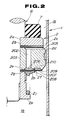
- the piston assembly 2 is fixedly mounted on the lower end portion of a piston rod 6 which is connected to a vehicular body at the upper end. As shown in Figs. 1 and 2 , the piston rod 6 has a smaller diameter piston receptacle section 6b with a threaded lower end 6a .
- the piston assembly 2 comprises a retainer 2a , a washer 2b , an upper valve plate 2c , a piston body 2d , a lower valve plate 2e , a smaller diameter disc plate 2f , a washer 2g , a retainer 2h and a valve spring 2j . These components of the piston assembly 2 is assembled to the piston receptacle section 6b of the piston rod 6 in order with a rubber bushing 7 , as shown.
- a fastening nut 2k engages with the threaded end 6a of the piston rod so that the piston assembly 2 can be firmly fixed onto the lower end portion of the piston rod.
- the piston body 2d is formed with a center opening 203 , through which the smaller diameter piston receptacle section 6b of the piston rod 6 extends.
- the piston body 2d is also formed with a plurality of through holes 201 and a plurality of orifices 202 at radially and circumferential]y offset position to each other.
- the through holes 201 extends oblique to the axis of the piston rod 6 and have upper ends opening to an outer annular groove 201a formed on the upper plane surface of the piston body 2d .
- the lower end of each of the through hole 201 directly opens to the lower working chamber 1b at the circumferentially extending tapered edge portion of the piston body.
- the orifices 202 extend in parallel to the axis of the piston rod 6 .
- Each of the orifices 202 has an upper end opening to an inner annular groove 202a .
- the inner annular groove 202a is formed coaxially with the outer annular groove 201a and separated by an annular land formed therebetween, which land has an upper plane surface 204 serving as a contact surface for establishing sealing contact with the lower surface of the upper valve plate 2c .
- Both of the annular grooves 201a and 202a are communicated with the upper working chamber 1a via a communication path groove 205 extending through the land.
- the lower end of each orifice 202 opens to an inner annular groove 206 .
- the annular groove 206 is formed on the lower plane surface of the piston body 2d .
- An outer annular groove 207 is coaxially formed with the inner annular groove 206 on the lower plane surface of the piston body 2d .
- These annular grooves 206 and 207 are generally separated by an annular land formed therebetween.
- the land has a plane lower surface 208 on which the upper surface of the lower valve plate 2e is seated for establishing sealing contact.
- Another and outer annular land is also formed on the lower surface of the piston rod, which outer annular land has a lower plane surface 209 to sealingly contact with the upper surface of the lower valve plate 2e .
- the annular grooves 206 and 207 are communicated to each other via a constant orifice 210 radially extending through the inner land.
- the lower valve plate 2e comprises three annular disc shaped members piled up or laminated to each other. These annular disc shaped members are formed by a resilient material such as leaf spring material, for resilient deformation in response to a working fluid pressure greater than a predetermined pressure. These annular discs are provided an initial resilient force to resiliently and sealingly contact with the surfaces 208 and 209 of the lands.
- the lower valve plate 2e is associated with the smaller diameter disc 2f .
- the smaller diameter disc 2f has outer diameter substantially corresponding to the external diameter of the inner annular groove 206 .
- the smaller diameter disc 2f is associated with a valve spring 2j which is retained by means of a retailer 2h .
- the valve spring 2j normally biases the smaller diameter disc 2f upwardly and whereby bias the lower valve plate 2e onto the surfaces 208 and 209 .
- the volume of the upper working chamber 1a decreases according to upward movement of the piston assembly 2 .
- the fluid pressure in the upper fluid chamber 1a increases.
- the volume of the lower working chamber 1b increase to lower the fluid pressure. Therefore, pressure balance is destroyed. Therefore, the working fluid in the upper working chamber 1a flows into the orifice 202 through the communication path groove 205 .
- the pressurized fluid flows through the inner groove 206 , the constant orifices 210 and the outer groove 207 .
- the circumferential portion of the valve plate 2e is deformed to permit the working fluid to flow into the lower working chamber 1b at a limited flow rate.
- the smaller diameter disk 2f and retainer 2h specifies the position to exert the spring force of the valve spring 2j at the position corresponding to the position of the valve plate 2e contacting with the surface 208 of the land. This stably define the position to exert the spring force.
- the resilience of the valve plate 2f can be adjusted by adjusting thickness of each resilient member as the component or by varying number of the resilient member to be laminated. Since the absorption characteristics is variable depending upon the stiffness of the valve plate 2e , by adjusting the thickness of the resilient member and/or changing number of the resilient plate, absorption characteristics can be adjusted for obtaining desired characteristics.
- the outer groove 207 may be provided wider width than the inner groove 206 for provided wider path area. This makes the greater force to be exerted on the section of the valve plate 2e corresponding to the groove 207 that that exerted on the section corresponding to the groove 206 . This assures that the section of the valve plate 2e mating with the surface 208 of the inner annular land is maintained sealing contact in the low piston stroke speed range. Therefore, in response to the low speed piston stroke, greater absorption can be generated in comparision with that to be created in response to the intermediate or high speed of piston stroke.
- the shock absorber for the automotive suspension system
- lower piston stroke speed and greater magnitude of vibration can be induced in a vehicle body to cause vehicular body attitude change.
- higher piston stroke speed and smaller magnitude of vibration can be input through the road wheels as road shock.
- the vehicle body induced vibration it is desired to generate sufficient damping force to suppress vehicular body attitude change for better driving stability.
- the road shock softer suspension characteristics so as not to transmit the vibration to the vehicle body for preventing rough ride feeling which otherwise caused by the vibration transmitted to the vehicle body. Therefore, the absorption characteristics provided by the aforementioned first embodiment of the shock absorber may accomplish both of the riding comfort and driving stability.
- the bottom valve assembly 3 comprises a valve spring 3b , a retainer 3c , a disc plate 3d , a lower valve plate 3e , a valve body 3f , an upper valve plate 3g , a washer 3h , s check spring 3j and a retainer 3k .
- These components are assembled to a bolt 3a in order, as shown.
- the components are secured to the bolt 3a by means of a fastening nut 3m .
- the valve body 3f is rigidly engaged to the lower end of the inner cylinder 1 to secure the bottom valve assembly 3 .
- the valve body 3f is formed with through holes 301 and orifices 302 .
- the upper end of the through holes 301 is closed be the valve plate 3g .
- the lower end of the through hold 301 is opened to the reservoir 4 .
- the lower ends of the orifices 302 open to an annular groove 206 which extends coaxially with an outer annular groove 207 .
- Inner and outer lands are formed along the circumferential edges of the outer annular grooves 207 form seat surfaces 208 and 209 for the valve plate 3e .
- the upper ends of the orifices 302 open to an annular groove formed on the upper surface of the valve body, which annular groove is in communication withe the lower working chamber 1b via a through openings 303 formed in the upper valve plate 3k . Therefore, the orifices permit fluid flow from the lower working chamber 1b to the reservoir chamber 4 and blocks fluid flow in the opposite direction.
- the bottom valve assembly 3 operates in two different mode depending upon the piston stroke. Each mode of operations will be discussed herebelow.
- the pressurized fluid flows through the through openings 303 , the annular groove on the upper surface of the valve body 3f and the orifices 302 and then flows through the constant orifice 210 formed through the inner annular land formed between the inner and outer grooves 206 and 207 .
- the fluid pressure in the groove 207 acts on the valve plate 3e to cause deformation for establishing fluid communication between the lower fluid chamber 1b and the fluid reservoir chamber 4 so as to permit the fluid flow from the lower working chamber to the fluid reservoir chamber.
- the magnitude of absorption produced at the constant orifice is proportional to two power of the piston stroke speed.
- the greater fluid pressure in the grooves 206 and 207 acts on the valve plate 3e to cause greater magnitude of deformation in the valve plate. Therefore, the valve plate 3e is placed away from the seating surface 208 as well as from the seating surface 209 . Therefore, the characteristics of variation of absorption becomes proportion to two over three power of the piston stroke speed.
- valve plate 3e comprises a plurality of resilient members laminated to each other.
- the variation characteristics of absorption can be adjusted by adjusting the thickness of each resilient member and/or by adjusting number of resilient members to be laminated.
- Fig. 7 shows modification of the foregoing first embodiment of the shock absorber according to the invention.
- the piston assembly has a valve body formed with through holes 7a , orifices 7b , an inner groove 7c , an outer groove 7e , inner and outer lands having valve seating surfaces 7d and 7f .
- Constant orifices 7g are formed through the inner annular land for establishing fluid communication between the inner and outer grooves 7c and 7e .
- the outer circumferential edge of the inner groove 7c and the inner circumferential edge of the outer groove 7e are parallel to each other and formed into non-circular configuration. Namely, the width of the inner groove 7c is widened at the orientation where the orifices 7b .
- Fig. 8 shows another modification of the foregoing first embodiment of the shock absorber according to the invention.
- the piston assembly has a valve body formed with through holes 8a , orifices 8b , an inner groove 8c , an outer groove 8e , inner and outer lands having valve seating surfaces 8d and 8f .
- Constant orifices 8g are formed through the inner annular land for establishing fluid communication between the inner and outer grooves 8c and 8e .
- the inner groove 8c is separated into a plurality of arc shaped segments oriented at the orientations where the orifices 8b is provided.
- Fig. 9 shows another modification of the foregoing first embodiment of the shock absorber according to the invention.
- the piston assembly has a valve body formed with through holes 9a , orifices 9b , an inner groove 9c , an outer groove 9e , inner and outer lands having valve seating surfaces 9d and 9f .
- Constant orifices 9g are formed through the inner annular land for establishing fluid communication between the inner and outer grooves 9c and 9e .
- the inner groove 9c is formed into circular configuration.
- the outer groove has alternatively arranged narrower width sections and wider width sections. The wider width sections are arranged at orientations where the constant orifices 9g are formed.
- Fig. 10 shows another modification of the foregoing first embodiment of the shock absorber according to the invention.
- the piston assembly has a valve body formed with through holes 10a , orifices 10b , an inner groove 10c , an outer groove 10e , inner and outer lands having valve seating surfaces 10d and 10f .
- Constant orifices 10g are formed through the inner annular land for establishing fluid communication between the inner and outer grooves 10c and 10e .
- the inner groove 10c is formed into circular configuration.
- the outer groove 10e is separated into a plurality of arc shaped segments oriented at the orientations where the constant orifices 10g are provided.
- Fig. 11 shows another modification of the foregoing first embodiment of the shock absorber according to the invention.
- the piston assembly has a valve body formed with through holes 11a , orifices 11b , an inner groove 11c , an outer groove 11e , inner and outer lands having valve seating surfaces 11d and 11f .
- Constant orifices 11g are formed through the inner annular land for establishing fluid communication between the inner and outer grooves 11c and 11e .
- the inner groove 11c is separated into a plurality of arc shaped segments.
- the outer groove 11e is also separated into a plurality of arc shaped segments oriented at the orientations where the constant orifices 11g are provided.
- Fig. 12 shows the second embodiment of a shock absorber according to the present invention.
- the shown embodiment has essentially the same construction to the aforementioned first embodiment except for the following particular points. Therefore, in order to avoid redundant discussion which may cause confusion, the common part will neglected from the drawings and discussion given herebelow.
- the lower surface 221 of the piston body 2d oriented at the inside of the inner annular groove 206 has height lower than the valve seating surface 209 of the outer annular land so that the valve seating surface 209 projects downwardly from the plane extending through the surface 221 .
- the height of the valve seating surface 208 is set lower than the level of the surface 221 .
- the downward distance from a reference plane a to respective surfaces 221 , 208 and 209 are respectively A , B and C . These three distances are so related to establish the relationship of C > A > B.
- valve plate 2e is deformed at the section between the surfaces 221 and 208 and at the section between the surfaces 208 and 209 . Therefore, the valve plate 2e can be set in prestressed fashion to increase contact force in contacting with the associated seating surface to assure liquid tight seal. This causes variation rate of the absorption relative to variation of the piston stroke speed can be increased. Furthermore, a pressure relieving point at the valve seating surface 208 can be risen to the higher level. This expands possible variation range of the absorption.
- Fig. 13 shows the third embodiment of the shock absorber according to the present invention.
- the shown embodiment of the shock absorber has essentially the identical construction to that of the first embodiment except for the construction of the constant orifices.
- the constant orifices formed through the land formed between the grooves 206 and 207 in the former embodiments are replaced by a hole or groove 330 formed in the uppermost resilient member 331 of the valve plate 2e .
- the second layer resilient member 332 forms the bottom of the hole 330 to define paths bypassing the land so as to form constant orifice between the valve seating surface 208 and the upper surface of the second layer resilient member 332 .
- the holes 330 are arranged with regular intervals.
- hole 330 in Fig. 14 can be replaced with the cut-out 333a illustrated in Fig. 15 .
- Figs. 16 and 17 shows the fourth embodiment of the shock absorber according to the present invention.
- the retainer 400 for the valve spring 21 is formed with a radially extending flange 401 having a diameter slightly greater than the diameter of the valve plate 2e .
- the flange 401 opposes to the valve plate 2e with a predetermined clearance D therebetween.
- the flange 401 serves as stopper flange for restricting deformation range of the valve plate 2e .
- the presence of the flange 401 allows to form the valve member with resilient members having lower resilient coefficient. Therefore, initial response of the valve member in causing deformation can be set higher. On the other hand, since the flange 401 prevents the valve plate 2e from causing excessive deformation.
- left of the valve plate can be expanded.
- the flange 401 of the retainer 400 in the embodiment of Fig. 17 can be replaced with a stopper plate 500 formed separately from the retainer 2h .
- the stopper plate 500 may provide substantially the same effect to that achieved by the embodiment of Fig. 17 .
- valve spring may comprise a progressive spring to vary the spring force depending upon the piston stroke.
- second and subsequent embodiments may be applicable not only for the piston assembly but also for the bottom valve assembly.
Landscapes
- Engineering & Computer Science (AREA)
- General Engineering & Computer Science (AREA)
- Mechanical Engineering (AREA)
- Fluid-Damping Devices (AREA)
Applications Claiming Priority (4)
| Application Number | Priority Date | Filing Date | Title |
|---|---|---|---|
| JP45454/88U | 1988-04-04 | ||
| JP4545488 | 1988-04-04 | ||
| JP1035486A JP3009151B2 (ja) | 1988-04-04 | 1989-02-15 | 液圧緩衝器 |
| JP35486/88 | 1989-02-15 |
Publications (3)
| Publication Number | Publication Date |
|---|---|
| EP0336692A2 true EP0336692A2 (fr) | 1989-10-11 |
| EP0336692A3 EP0336692A3 (en) | 1990-03-21 |
| EP0336692B1 EP0336692B1 (fr) | 1993-11-03 |
Family
ID=26374487
Family Applications (1)
| Application Number | Title | Priority Date | Filing Date |
|---|---|---|---|
| EP89303292A Expired - Lifetime EP0336692B1 (fr) | 1988-04-04 | 1989-04-04 | Amortisseur de chocs |
Country Status (7)
| Country | Link |
|---|---|
| US (1) | US4905799A (fr) |
| EP (1) | EP0336692B1 (fr) |
| JP (1) | JP3009151B2 (fr) |
| KR (1) | KR930001572B1 (fr) |
| AU (1) | AU608965B2 (fr) |
| CA (1) | CA1315301C (fr) |
| DE (1) | DE68910365T2 (fr) |
Cited By (7)
| Publication number | Priority date | Publication date | Assignee | Title |
|---|---|---|---|---|
| DE3932258A1 (de) * | 1988-09-27 | 1990-04-19 | Atsugi Unisia Corp | Hydraulischer stossdaempfer mit kolbendichtung fuer ein verbessertes anfangs-ansprechverhalten |
| DE4005657A1 (de) * | 1989-02-22 | 1990-09-13 | Atsugi Unisia Corp | Stossdaempfer mit variabler daempfungskraft und variabler drosseloeffnung zur einstellung der daempfungscharakteristika |
| US5226512A (en) * | 1989-02-22 | 1993-07-13 | Atsugi Unisia Corporation | Variable damping force shock absorber with variable orifice for adjusting damping characteristics |
| US5738190A (en) * | 1996-03-20 | 1998-04-14 | Monroe Auto Equipment Company | Flexing disc-blow off assembly for use in a shock absorber |
| WO2008000460A3 (fr) * | 2006-06-27 | 2008-06-05 | Thyssenkrupp Bilstein Suspensi | Élément d'amortissement |
| US20140090940A1 (en) * | 2012-09-28 | 2014-04-03 | Hitachi Automotive Systems, Ltd. | Shock absorber |
| WO2018202386A1 (fr) * | 2017-05-05 | 2018-11-08 | Zf Friedrichshafen Ag | Clapet d'amortissement pour amortisseur de vibrations |
Families Citing this family (47)
| Publication number | Priority date | Publication date | Assignee | Title |
|---|---|---|---|---|
| US5277283A (en) * | 1988-09-19 | 1994-01-11 | Atsugi Unisia Corporation | Variable damping-characteristics shock absorber with adjustable orifice construction variable of fluid flow restriction depending upon fluid pressure difference |
| US5042624A (en) * | 1988-09-29 | 1991-08-27 | Atsugi Unisia Corporation | Hydraulic shock absorber with pre-loaded valve for linear variation characteristics of damping force |
| GB2226620B (en) * | 1988-10-25 | 1992-11-04 | Tokico Ltd | Hydraulic damper |
| JPH0292154U (fr) * | 1989-01-10 | 1990-07-23 | ||
| US5219414A (en) * | 1989-04-24 | 1993-06-15 | Atsugi Unisia Corporation | Variable damping force shock absorber with stroke dependent variation characteristics of damping force |
| US5133434A (en) * | 1989-06-15 | 1992-07-28 | Atsugi Unisia Corporation | Variable damping force shock absorber with feature of independent adjustment of damping characteristics for bounding a rebounding strokes |
| US5193655A (en) * | 1989-09-20 | 1993-03-16 | Atsugia Unisia Corp. | Variable damping force shock absorber with feature of linear and wide range damping force variation depending upon piston stroke speed |
| JP2918293B2 (ja) * | 1990-05-28 | 1999-07-12 | 株式会社ユニシアジェックス | 減衰力可変型緩衝器 |
| US5595269A (en) * | 1993-05-10 | 1997-01-21 | Fichtel & Sachs Ag | Vibration damper for a motor vehicle |
| US5460357A (en) * | 1994-04-29 | 1995-10-24 | Answer Products, Inc. | Multi-function sleeves used in conjunction with replaceable elastomers for adjustable shock-absorbing suspension systems of bicycles and motorcycles |
| US5515669A (en) * | 1995-02-03 | 1996-05-14 | The Shivvers Group, Inc. | Anti-buck device for out-front mower tractors |
| US5784867A (en) * | 1995-10-03 | 1998-07-28 | Shivvers Incorporated | Variable force traction enhance systems |
| US6499572B2 (en) | 1996-04-10 | 2002-12-31 | Kayaba Kogyo Kabushiki Kaisha | Damping force generator |
| US6352145B1 (en) | 1998-10-07 | 2002-03-05 | Tenneco Automotive Inc. | Stroke dependent damping |
| US6371264B1 (en) * | 1999-06-09 | 2002-04-16 | Denso Corporation | Fulcrum blow off valve for use in a shock absorber |
| US6464053B1 (en) | 1999-07-26 | 2002-10-15 | Tenneco Automotive Operating Company, Inc. | Single piece piston |
| US6390257B1 (en) * | 2000-02-16 | 2002-05-21 | Delphi Technologies, Inc. | Suspension damper having piston plate with coined, continuously curved bypass |
| US6672436B1 (en) * | 2000-04-19 | 2004-01-06 | Tenneco Automotive Operating Company Inc. | Variable bleed orifice valving |
| US7070028B2 (en) | 2001-02-07 | 2006-07-04 | Tenneco Automotive Operating Company Inc. | Frequency dependent damper |
| US6886670B2 (en) * | 2003-09-29 | 2005-05-03 | Tenneco Automotive Operating Company Inc. | Extra support land for valve disc |
| GB2437182B (en) * | 2003-09-29 | 2008-05-21 | Tenneco Automotive Operating | Extra support area for valve disc |
| GB2437185B (en) * | 2003-09-29 | 2008-05-14 | Tenneco Automotive Operating | Extra support land for valve disc |
| US6899207B2 (en) * | 2003-09-29 | 2005-05-31 | Tenneco Automotive Operating Company Inc. | Extra support area for valve disc |
| JP2006132555A (ja) * | 2004-11-02 | 2006-05-25 | Kayaba Ind Co Ltd | 減衰力発生部構造 |
| US20060231358A1 (en) * | 2005-04-15 | 2006-10-19 | Arvinmeritor Technology, Llc | Pre-load ring for shock absorber |
| JP4868166B2 (ja) * | 2007-11-30 | 2012-02-01 | 日立オートモティブシステムズ株式会社 | 流体圧緩衝器 |
| JP5290701B2 (ja) * | 2008-03-26 | 2013-09-18 | 日立オートモティブシステムズ株式会社 | 流体圧緩衝器 |
| JP5115814B2 (ja) * | 2008-05-30 | 2013-01-09 | 日立オートモティブシステムズ株式会社 | 緩衝器 |
| US20100163355A1 (en) | 2008-12-25 | 2010-07-01 | Hiroyuki Yamaguchi | Shock absorber |
| JP5192441B2 (ja) * | 2009-05-20 | 2013-05-08 | カヤバ工業株式会社 | 減衰バルブ |
| JP2011179550A (ja) * | 2010-02-26 | 2011-09-15 | Hitachi Automotive Systems Ltd | 緩衝器 |
| US9169890B2 (en) * | 2011-07-21 | 2015-10-27 | Tenneco Automotive Operating Company Inc. | Low noise valve assembly |
| JP6071646B2 (ja) | 2012-11-30 | 2017-02-01 | 日立オートモティブシステムズ株式会社 | 緩衝器 |
| US9067471B2 (en) * | 2013-03-15 | 2015-06-30 | Tenneco Automotive Operating Company Inc. | Piston assembly with open bleed |
| JP5783646B2 (ja) * | 2013-11-08 | 2015-09-24 | カヤバ工業株式会社 | バルブ |
| JP5783647B2 (ja) * | 2013-11-08 | 2015-09-24 | カヤバ工業株式会社 | バルブ |
| JP6408813B2 (ja) * | 2014-07-17 | 2018-10-17 | Kyb株式会社 | 緩衝器 |
| JP6487804B2 (ja) * | 2015-08-07 | 2019-03-20 | Kyb株式会社 | 緩衝器のバルブ構造 |
| JP6754624B2 (ja) * | 2016-06-15 | 2020-09-16 | 日立オートモティブシステムズ株式会社 | 緩衝器 |
| KR20180083721A (ko) * | 2017-01-13 | 2018-07-23 | 주식회사 만도 | 쇽업소버의 밸브구조 |
| WO2019239521A1 (fr) * | 2018-06-13 | 2019-12-19 | 株式会社ショーワ | Amortisseur de chocs de pression |
| US11668365B2 (en) * | 2019-09-23 | 2023-06-06 | DRiV Automotive Inc. | Valve body for a damper |
| JP2021169829A (ja) * | 2020-04-14 | 2021-10-28 | 日立Astemo株式会社 | 緩衝器 |
| CN113586643B (zh) * | 2020-04-30 | 2022-09-06 | 比亚迪股份有限公司 | 减振器及车辆 |
| JP7481929B2 (ja) * | 2020-07-03 | 2024-05-13 | カヤバ株式会社 | 緩衝器 |
| US20240376953A1 (en) * | 2023-05-08 | 2024-11-14 | DRiV Automotive Inc. | Fulcrum and check discs for shock absorber with optimized bleed range and tuneability |
| WO2025177648A1 (fr) * | 2024-02-22 | 2025-08-28 | Astemo株式会社 | Corps fritté et procédé de production d'un corps fritté |
Family Cites Families (9)
| Publication number | Priority date | Publication date | Assignee | Title |
|---|---|---|---|---|
| FR1545406A (fr) * | 1967-11-27 | 1968-11-08 | Rheinmetall Gmbh | Amortisseur hydraulique d'oscillations |
| GB1221970A (en) * | 1968-10-01 | 1971-02-10 | Woodhead Mfg Company Ltd | Hydraulic shock-absorbers |
| US4076276A (en) * | 1976-07-09 | 1978-02-28 | Monroe Auto Equipment Company | Base valve for independent wheel suspension strut |
| DE3109122A1 (de) * | 1981-03-11 | 1982-09-23 | Fichtel & Sachs Ag, 8720 Schweinfurt | Federscheibe fuer ein ventil |
| JPS6147134U (ja) * | 1984-08-31 | 1986-03-29 | 株式会社 昭和製作所 | 油圧緩衝器の減衰力発生装置 |
| JPH0231615Y2 (fr) * | 1985-12-26 | 1990-08-27 | ||
| JPS62155346A (ja) * | 1985-12-27 | 1987-07-10 | Toyota Motor Corp | 液圧緩衝器の弁構造 |
| JP2570266B2 (ja) * | 1986-07-25 | 1997-01-08 | トヨタ自動車株式会社 | 液圧緩衝器 |
| US4809829A (en) * | 1987-12-08 | 1989-03-07 | Maremont Corporation | Vehicular shock absorber and piston comfort valving |
-
1989
- 1989-02-15 JP JP1035486A patent/JP3009151B2/ja not_active Expired - Lifetime
- 1989-04-03 US US07/332,469 patent/US4905799A/en not_active Expired - Fee Related
- 1989-04-04 AU AU32415/89A patent/AU608965B2/en not_active Ceased
- 1989-04-04 DE DE89303292T patent/DE68910365T2/de not_active Expired - Fee Related
- 1989-04-04 KR KR1019890004438A patent/KR930001572B1/ko not_active Expired - Fee Related
- 1989-04-04 CA CA000595582A patent/CA1315301C/fr not_active Expired - Fee Related
- 1989-04-04 EP EP89303292A patent/EP0336692B1/fr not_active Expired - Lifetime
Cited By (11)
| Publication number | Priority date | Publication date | Assignee | Title |
|---|---|---|---|---|
| DE3932258A1 (de) * | 1988-09-27 | 1990-04-19 | Atsugi Unisia Corp | Hydraulischer stossdaempfer mit kolbendichtung fuer ein verbessertes anfangs-ansprechverhalten |
| DE4005657A1 (de) * | 1989-02-22 | 1990-09-13 | Atsugi Unisia Corp | Stossdaempfer mit variabler daempfungskraft und variabler drosseloeffnung zur einstellung der daempfungscharakteristika |
| US5226512A (en) * | 1989-02-22 | 1993-07-13 | Atsugi Unisia Corporation | Variable damping force shock absorber with variable orifice for adjusting damping characteristics |
| US5738190A (en) * | 1996-03-20 | 1998-04-14 | Monroe Auto Equipment Company | Flexing disc-blow off assembly for use in a shock absorber |
| US6085876A (en) * | 1996-03-20 | 2000-07-11 | Tenneco Automotive Inc. | Flexing disc-blow off assembly for use in a shock absorber |
| DE19710454B4 (de) * | 1996-03-20 | 2004-02-12 | Tenneco Automotive Inc., Monroe | Stoßdämpfer mit Zugstufenventil |
| WO2008000460A3 (fr) * | 2006-06-27 | 2008-06-05 | Thyssenkrupp Bilstein Suspensi | Élément d'amortissement |
| US8235188B2 (en) | 2006-06-27 | 2012-08-07 | Thyssenkrupp Bilstein Suspension Gmbh | Damping element |
| US20140090940A1 (en) * | 2012-09-28 | 2014-04-03 | Hitachi Automotive Systems, Ltd. | Shock absorber |
| US9194455B2 (en) * | 2012-09-28 | 2015-11-24 | Hitachi Automotive Systems, Ltd. | Shock absorber |
| WO2018202386A1 (fr) * | 2017-05-05 | 2018-11-08 | Zf Friedrichshafen Ag | Clapet d'amortissement pour amortisseur de vibrations |
Also Published As
| Publication number | Publication date |
|---|---|
| JPH0266333A (ja) | 1990-03-06 |
| CA1315301C (fr) | 1993-03-30 |
| US4905799A (en) | 1990-03-06 |
| DE68910365T2 (de) | 1994-03-17 |
| AU3241589A (en) | 1989-10-05 |
| KR890015895A (ko) | 1989-11-27 |
| EP0336692A3 (en) | 1990-03-21 |
| DE68910365D1 (de) | 1993-12-09 |
| KR930001572B1 (ko) | 1993-03-05 |
| AU608965B2 (en) | 1991-04-18 |
| EP0336692B1 (fr) | 1993-11-03 |
| JP3009151B2 (ja) | 2000-02-14 |
Similar Documents
| Publication | Publication Date | Title |
|---|---|---|
| US4905799A (en) | Shock absorber | |
| US4964493A (en) | Shock absorber with variable damping characteristics depending upon stroke speed | |
| US5042624A (en) | Hydraulic shock absorber with pre-loaded valve for linear variation characteristics of damping force | |
| US5219414A (en) | Variable damping force shock absorber with stroke dependent variation characteristics of damping force | |
| EP1158202B2 (fr) | Canal de passage variable, accordable indépendamment | |
| EP1664578B1 (fr) | Derivation dependant de la course | |
| US6672436B1 (en) | Variable bleed orifice valving | |
| US4795009A (en) | Twin-tube type shock absorber | |
| KR102173633B1 (ko) | 완충기 및 이것을 이용한 차량 | |
| US6332622B1 (en) | Suspension apparatus having two interconnected shock absorbers | |
| JP5909557B2 (ja) | サスペンション装置 | |
| GB2335476A (en) | Acceleration sensitive damping for automotive dampers | |
| EP1312828B1 (fr) | Amortisseur sensible à l'accélération | |
| US5158161A (en) | Reverse installation type variable damping force shock absorber variable of damping characteristics both for bounding and rebounding stroke motions | |
| US4418802A (en) | Shock absorber | |
| CN114810911A (zh) | 冲程依赖性阻尼器组件 | |
| US5226512A (en) | Variable damping force shock absorber with variable orifice for adjusting damping characteristics | |
| US6230858B1 (en) | Internally slotted orifice disc for low speed control in automotive dampers | |
| US5193655A (en) | Variable damping force shock absorber with feature of linear and wide range damping force variation depending upon piston stroke speed | |
| EP0095760A2 (fr) | Amortisseur de choc à écoulement tourbillonnant et à effet variable avec la course du piston | |
| EP1664581B1 (fr) | Amortisseur | |
| US20250257785A1 (en) | Damper assembly with frequency adaptive orifice | |
| EP0336758B1 (fr) | Amortisseur de chocs ayant des caractéristiques d'amortissement variables selon la vitesse de déplacement du piston | |
| US6148969A (en) | Frequency dependant damper | |
| US12385545B2 (en) | Damper assembly with frequency adaptive orifice |
Legal Events
| Date | Code | Title | Description |
|---|---|---|---|
| PUAI | Public reference made under article 153(3) epc to a published international application that has entered the european phase |
Free format text: ORIGINAL CODE: 0009012 |
|
| AK | Designated contracting states |
Kind code of ref document: A2 Designated state(s): DE FR GB |
|
| PUAL | Search report despatched |
Free format text: ORIGINAL CODE: 0009013 |
|
| AK | Designated contracting states |
Kind code of ref document: A3 Designated state(s): DE FR GB |
|
| 17P | Request for examination filed |
Effective date: 19900903 |
|
| 17Q | First examination report despatched |
Effective date: 19920303 |
|
| RAP1 | Party data changed (applicant data changed or rights of an application transferred) |
Owner name: ATSUGI UNISIA CORPORATION |
|
| GRAA | (expected) grant |
Free format text: ORIGINAL CODE: 0009210 |
|
| AK | Designated contracting states |
Kind code of ref document: B1 Designated state(s): DE FR GB |
|
| REF | Corresponds to: |
Ref document number: 68910365 Country of ref document: DE Date of ref document: 19931209 |
|
| ET | Fr: translation filed | ||
| PLBE | No opposition filed within time limit |
Free format text: ORIGINAL CODE: 0009261 |
|
| STAA | Information on the status of an ep patent application or granted ep patent |
Free format text: STATUS: NO OPPOSITION FILED WITHIN TIME LIMIT |
|
| 26N | No opposition filed | ||
| PGFP | Annual fee paid to national office [announced via postgrant information from national office to epo] |
Ref country code: GB Payment date: 19990408 Year of fee payment: 11 |
|
| PGFP | Annual fee paid to national office [announced via postgrant information from national office to epo] |
Ref country code: FR Payment date: 19990409 Year of fee payment: 11 Ref country code: DE Payment date: 19990409 Year of fee payment: 11 |
|
| PG25 | Lapsed in a contracting state [announced via postgrant information from national office to epo] |
Ref country code: GB Free format text: LAPSE BECAUSE OF NON-PAYMENT OF DUE FEES Effective date: 20000404 |
|
| GBPC | Gb: european patent ceased through non-payment of renewal fee |
Effective date: 20000404 |
|
| PG25 | Lapsed in a contracting state [announced via postgrant information from national office to epo] |
Ref country code: FR Free format text: LAPSE BECAUSE OF NON-PAYMENT OF DUE FEES Effective date: 20001229 |
|
| PG25 | Lapsed in a contracting state [announced via postgrant information from national office to epo] |
Ref country code: DE Free format text: LAPSE BECAUSE OF NON-PAYMENT OF DUE FEES Effective date: 20010201 |
|
| REG | Reference to a national code |
Ref country code: FR Ref legal event code: ST |