EP0336858B1 - Aufwickelbremse für Rollbandmass - Google Patents
Aufwickelbremse für Rollbandmass Download PDFInfo
- Publication number
- EP0336858B1 EP0336858B1 EP89420111A EP89420111A EP0336858B1 EP 0336858 B1 EP0336858 B1 EP 0336858B1 EP 89420111 A EP89420111 A EP 89420111A EP 89420111 A EP89420111 A EP 89420111A EP 0336858 B1 EP0336858 B1 EP 0336858B1
- Authority
- EP
- European Patent Office
- Prior art keywords
- drum
- housing
- winding
- brake according
- cradles
- Prior art date
- Legal status (The legal status is an assumption and is not a legal conclusion. Google has not performed a legal analysis and makes no representation as to the accuracy of the status listed.)
- Expired - Lifetime
Links
- 210000002105 tongue Anatomy 0.000 claims description 22
- 238000004804 winding Methods 0.000 claims description 22
- 238000005096 rolling process Methods 0.000 description 4
- 230000000694 effects Effects 0.000 description 3
- 238000005259 measurement Methods 0.000 description 2
- 239000002184 metal Substances 0.000 description 2
- 230000035939 shock Effects 0.000 description 2
- 238000011144 upstream manufacturing Methods 0.000 description 2
- YFXPPSKYMBTNAV-UHFFFAOYSA-N bensultap Chemical compound C=1C=CC=CC=1S(=O)(=O)SCC(N(C)C)CSS(=O)(=O)C1=CC=CC=C1 YFXPPSKYMBTNAV-UHFFFAOYSA-N 0.000 description 1
- 230000007547 defect Effects 0.000 description 1
- 230000006866 deterioration Effects 0.000 description 1
- 238000000465 moulding Methods 0.000 description 1
Images
Classifications
-
- G—PHYSICS
- G01—MEASURING; TESTING
- G01B—MEASURING LENGTH, THICKNESS OR SIMILAR LINEAR DIMENSIONS; MEASURING ANGLES; MEASURING AREAS; MEASURING IRREGULARITIES OF SURFACES OR CONTOURS
- G01B3/00—Measuring instruments characterised by the use of mechanical techniques
- G01B3/10—Measuring tapes
- G01B3/1005—Means for controlling winding or unwinding of tapes
-
- B—PERFORMING OPERATIONS; TRANSPORTING
- B65—CONVEYING; PACKING; STORING; HANDLING THIN OR FILAMENTARY MATERIAL
- B65H—HANDLING THIN OR FILAMENTARY MATERIAL, e.g. SHEETS, WEBS, CABLES
- B65H75/00—Storing webs, tapes, or filamentary material, e.g. on reels
- B65H75/02—Cores, formers, supports, or holders for coiled, wound, or folded material, e.g. reels, spindles, bobbins, cop tubes, cans, mandrels or chucks
- B65H75/34—Cores, formers, supports, or holders for coiled, wound, or folded material, e.g. reels, spindles, bobbins, cop tubes, cans, mandrels or chucks specially adapted or mounted for storing and repeatedly paying-out and re-storing lengths of material provided for particular purposes, e.g. anchored hoses, power cables
- B65H75/38—Cores, formers, supports, or holders for coiled, wound, or folded material, e.g. reels, spindles, bobbins, cop tubes, cans, mandrels or chucks specially adapted or mounted for storing and repeatedly paying-out and re-storing lengths of material provided for particular purposes, e.g. anchored hoses, power cables involving the use of a core or former internal to, and supporting, a stored package of material
- B65H75/44—Constructional details
- B65H75/4436—Arrangements for yieldably braking the reel or the material for moderating speed of winding or unwinding
- B65H75/4442—Arrangements for yieldably braking the reel or the material for moderating speed of winding or unwinding acting on the reel
-
- F—MECHANICAL ENGINEERING; LIGHTING; HEATING; WEAPONS; BLASTING
- F16—ENGINEERING ELEMENTS AND UNITS; GENERAL MEASURES FOR PRODUCING AND MAINTAINING EFFECTIVE FUNCTIONING OF MACHINES OR INSTALLATIONS; THERMAL INSULATION IN GENERAL
- F16D—COUPLINGS FOR TRANSMITTING ROTATION; CLUTCHES; BRAKES
- F16D2129/00—Type of operation source for auxiliary mechanisms
- F16D2129/04—Mechanical
- F16D2129/043—Weights
-
- G—PHYSICS
- G01—MEASURING; TESTING
- G01B—MEASURING LENGTH, THICKNESS OR SIMILAR LINEAR DIMENSIONS; MEASURING ANGLES; MEASURING AREAS; MEASURING IRREGULARITIES OF SURFACES OR CONTOURS
- G01B3/00—Measuring instruments characterised by the use of mechanical techniques
- G01B3/10—Measuring tapes
- G01B3/1005—Means for controlling winding or unwinding of tapes
- G01B3/1007—Means for locking
- G01B2003/101—Means for locking acting on the drum
-
- G—PHYSICS
- G01—MEASURING; TESTING
- G01B—MEASURING LENGTH, THICKNESS OR SIMILAR LINEAR DIMENSIONS; MEASURING ANGLES; MEASURING AREAS; MEASURING IRREGULARITIES OF SURFACES OR CONTOURS
- G01B3/00—Measuring instruments characterised by the use of mechanical techniques
- G01B3/10—Measuring tapes
- G01B3/1005—Means for controlling winding or unwinding of tapes
- G01B3/102—Means for damping
Definitions
- Rolling measures are generally composed of a drum which, carrying the measuring tape and mounted free in rotation on an axis secured to a housing, is connected to this axis by a spring in spiral housed inside this drum.
- the object of the present invention is to provide a weighted winding brake which is light in weight and which provides much more effective braking during winding than during unwinding.
- This brake is of the type comprising weights cooperating with a circular track during rotation in the drum housing carrying the graduated ribbon.
- these weights are arranged transversely in a housing formed between one of the diametrical walls of the housing and the cheek opposite the drum, this housing having a cylindrical friction face , and are arranged radially between, on the one hand, an inner cradle secured to the drum, and on the other hand, the free end of an external elastic tongue which, substantially circular, is secured to the cradle along its other end, end disposed downstream during winding, and is capable of coming into frictional contact with the cylindrical frictional face of the housing.
- each counterweight tends, under the action of centrifugal force, to apply the free end of the corresponding tongue against the cylindrical friction face of the housing.
- the tongue is either pulled or pushed.
- the reaction forces due to its friction against the casing tend to move it away from it and consequently to reduce the surface in friction and the resistant effort from its friction.
- this tongue is pushed, that is to say during winding, the reaction forces due to friction on the housing tend to press this tongue more on the housing, thereby increasing the friction surfaces in contact and consequently the application and braking effort.
- This simple, light and inexpensive device thus ensures more effective braking during winding.
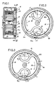
- this measuring tape is composed of a housing 2 which, in this embodiment, is in two parts, of a drum 3 mounted freely in rotation on a central axis 4 of the housing, of a spring in a spiral 5, one of the ends 6a of which is linked to the drum 3 and the other end of which 6b of which is linked to the axis 4 and, finally, of one meter ribbon 7, one end of which is hooked at 7a to the drum 4.
- the housing has an opening for the passage of the other end of the ribbon 7.
- this measuring tape is provided with a winding brake arranged in a housing 10 formed between the diametrical wall 12 of the housing 2 and the face 13 of the cheek 3a of the drum 3.
- This device consists of two weights 14 arranged in cradles 15 integral with the abovementioned cheek 3a. Each of the weights is constituted by a metal disc of generally cylindrical shape.
- the two cradles 15 are diametrically opposite on either side of the axis 4 and are arranged back to back with their concavity facing outwards.
- the braking device also comprises two elastic tongues 16, one of the ends 16a of which is free, and comes in front of the following counterweight and the other end of which is linked to the cheek 3a of the drum.
- this last end is integral with the corresponding cradle 15.
- These tongues are arranged so that their ends 16b linked to the drum are upstream relative to their end 16a when the drum is driven in the direction of the unwinding represented by the arrow 17 in FIG. 2.
- These generally semi-circular tongues face a cylindrical friction face 18 formed on the periphery of the housing 10 of the housing.
- the tongues 16 and the cradles 14 can be produced independently of the drum and be attached to it by clipping or any other means, but can also be produced at the same time as the drum. Under these conditions, and to facilitate the molding operation, the tongues 16 have an inside diameter larger than the outside diameter of the drum 3.
- the tongues 16 are pulled by the drum 3, that is to say have at their free ends 16a which are downstream relative to the direction of rotation.
- the counterweights 14 are subjected to a radial centrifugal force towards the outside which, as shown by the arrows FC, tends to press them against the free end 16a of the tongues 16 and, consequently, which tends to press these tongues against the friction face 18.
- the housing exerts, on the end 16a of the tongue, on the one hand, a radial reaction force FR opposing the centrifugal force and on the other hand , a tangential force FT opposing the advancement of the corresponding tongue.
- These two forces FR and FT form a component FK which is inclined downstream and therefore tends to pull the end 16a of each tongue and to move its curved central part away from the friction face 18.
- the component FK of the reaction forces tends to push the tongue and press its central part against the friction face 18, which has the effect of increasing the surfaces in contact and, by the friction which results therefrom , to increase the braking force.
- the braking device provides a minimal resistant torque, during winding, it provides a much greater resistant force ensuring the desired effects. It should be noted that this simple device is not very bulky, very light, and by the simplicity of the parts making it up, is inexpensive.
Landscapes
- Physics & Mathematics (AREA)
- General Physics & Mathematics (AREA)
- Tape Measures (AREA)
- Braking Arrangements (AREA)
Claims (5)
Applications Claiming Priority (2)
| Application Number | Priority Date | Filing Date | Title |
|---|---|---|---|
| FR8804639A FR2629541B1 (fr) | 1988-04-01 | 1988-04-01 | Frein d'envidage pour mesure roulante |
| FR8804639 | 1988-04-01 |
Publications (2)
| Publication Number | Publication Date |
|---|---|
| EP0336858A1 EP0336858A1 (de) | 1989-10-11 |
| EP0336858B1 true EP0336858B1 (de) | 1991-09-04 |
Family
ID=9365092
Family Applications (1)
| Application Number | Title | Priority Date | Filing Date |
|---|---|---|---|
| EP89420111A Expired - Lifetime EP0336858B1 (de) | 1988-04-01 | 1989-03-29 | Aufwickelbremse für Rollbandmass |
Country Status (5)
| Country | Link |
|---|---|
| US (1) | US4907756A (de) |
| EP (1) | EP0336858B1 (de) |
| DE (1) | DE68900233D1 (de) |
| ES (1) | ES2025852T3 (de) |
| FR (1) | FR2629541B1 (de) |
Families Citing this family (15)
| Publication number | Priority date | Publication date | Assignee | Title |
|---|---|---|---|---|
| US5423494A (en) * | 1992-01-10 | 1995-06-13 | Daido Tokushuko Kabushiki Kaisha | Pet rope winder |
| JP3222335B2 (ja) * | 1994-10-25 | 2001-10-29 | 株式会社ケイディエス | 測定用テープ巻取装置 |
| GB9517187D0 (en) * | 1995-08-22 | 1995-10-25 | Tensator Ltd | Speed governor for a rotational drive |
| DE20219191U1 (de) * | 2002-12-11 | 2003-02-20 | Lu, Jin-Chu, Lu Zhou Shi, Taipeh | Bandmass |
| US6792893B1 (en) | 2003-01-28 | 2004-09-21 | Diane Ellen Quintero | Retractable two-pet leash |
| US6866128B2 (en) * | 2003-02-20 | 2005-03-15 | Bellsouth Intellectual Property Corporation | Retractable anti-static devices and methods of using same |
| US20050011082A1 (en) * | 2003-07-14 | 2005-01-20 | Smith Michael J. | Tape measure device |
| BRMU8400821Y1 (pt) * | 2004-04-30 | 2014-05-20 | Ricardo Augusto De Lorenzo | Disposição construtiva em freio de cartucho de fita para postes de organização de filas |
| US8056849B2 (en) * | 2006-02-16 | 2011-11-15 | Black & Decker Inc. | Braking mechanism and tape cartridge for tape measure |
| US7360320B2 (en) * | 2006-04-26 | 2008-04-22 | Kelley Timothy J | Measuring device having flexible tape coiled around a plurality of reels |
| US20080263886A1 (en) * | 2007-04-24 | 2008-10-30 | Dong Hun Kang | Tape measure with a self-regulating speed control mechanism |
| US8251020B2 (en) * | 2010-03-12 | 2012-08-28 | Unleashed Products, LLC | Leash having a speed-limiting braking mechanism and system and method for using same |
| US10054415B2 (en) | 2015-09-30 | 2018-08-21 | Milwaukee Electric Tool Corporation | Tape measure |
| CN114485309B (zh) | 2017-03-24 | 2024-08-02 | 米沃奇电动工具公司 | 具有基于流体的收回速度控制器的卷尺 |
| US11231261B2 (en) * | 2017-12-01 | 2022-01-25 | Milwaukee Electric Tool Corporation | Tape measure with multiple spring retraction |
Family Cites Families (6)
| Publication number | Priority date | Publication date | Assignee | Title |
|---|---|---|---|---|
| FR598648A (fr) * | 1925-05-20 | 1925-12-21 | F Husson Et Vaillant Ets | Ruban à mesurer |
| US2896912A (en) * | 1955-11-15 | 1959-07-28 | Faugier Gabriel | Safety apparatus |
| FR1436086A (fr) * | 1965-03-13 | 1966-04-22 | Quenot & Cie Sarl | Dispositif d'enroulement d'un ruban souple en acier pour mesures linéaires |
| US3480227A (en) * | 1968-05-21 | 1969-11-25 | Duplex Inc | Retractor device with compensating brake |
| DE7225490U (de) * | 1972-07-07 | 1972-12-14 | Siemens-Electrogeraete Gmbh | Kabeltrommel |
| US3889897A (en) * | 1973-09-26 | 1975-06-17 | Stanley Works | Coilable tape measuring device having a self-regulating speed control mechanism |
-
1988
- 1988-04-01 FR FR8804639A patent/FR2629541B1/fr not_active Expired - Lifetime
-
1989
- 1989-03-29 ES ES198989420111T patent/ES2025852T3/es not_active Expired - Lifetime
- 1989-03-29 EP EP89420111A patent/EP0336858B1/de not_active Expired - Lifetime
- 1989-03-29 DE DE8989420111T patent/DE68900233D1/de not_active Expired - Lifetime
- 1989-04-25 US US07/342,837 patent/US4907756A/en not_active Expired - Fee Related
Also Published As
| Publication number | Publication date |
|---|---|
| US4907756A (en) | 1990-03-13 |
| ES2025852T3 (es) | 1992-04-01 |
| EP0336858A1 (de) | 1989-10-11 |
| FR2629541B1 (fr) | 1991-03-15 |
| FR2629541A1 (fr) | 1989-10-06 |
| DE68900233D1 (de) | 1991-10-10 |
Similar Documents
| Publication | Publication Date | Title |
|---|---|---|
| EP0336858B1 (de) | Aufwickelbremse für Rollbandmass | |
| EP0030494A1 (de) | Mechanische Steuerung durch axial verschiebbares Kabel in einem flexiblen Mantel | |
| FR2596832A1 (fr) | Embrayage centrifuge | |
| FR2615150A1 (fr) | Enrouleur de ceinture de securite avec dispositif de tension | |
| FR2809147A1 (fr) | Embrayage a friction a dispositif de rattrapage de jeu pilote pour vehicule automobile | |
| CH420639A (fr) | Dispositif d'enroulement d'un ruban souple pour mesures linéaires | |
| FR2532180A1 (fr) | Dispositif d'accouplement pour l'arbre d'enroulement d'un enrouleur de ceinture de securite a systeme tendeur de rappel | |
| WO2000028229A1 (fr) | Embrayage a friction a dispositif de rattrapage d'usure des garnitures de friction, en particulier pour vehicule automobile, equipe de moyens d'information du degre de ladite usure | |
| FR2765618A1 (fr) | Treuil a cordon comportant un organe d'embrayage/debrayage destine a manoeuvrer l'arbre porte-tablier d'un volet roulant | |
| FR2737268A1 (fr) | Ensemble formant disque amortisseur comportant des ressorts a deplacement radial limite | |
| FR2512287A1 (fr) | Dispositif destine a assurer le bobinage et le debobinage des cables electriques en exploitation | |
| EP0195172B1 (de) | Freilaufeinrichtung, insbesondere für den Radantrieb eines Selbstfahrrasenmähers | |
| EP0087376A1 (de) | Vorrichtung zum Spulen von Textilmaterialien die ein Bremselement zur Stillsetzung des Wickels am Ende des Spulvorganges hat | |
| FR2538485A1 (fr) | Dispositif de reajustement du reglage des garnitures d'un frein a friction, notamment d'un frein a tambour | |
| EP3245416B1 (de) | Verschleisseinstellungsmechanismus für eine kupplungsvorrichtung, insbesondere für kraftfahrzeuge | |
| FR2661721A1 (fr) | Embrayage autonome a friction avec disque mene a faible inertie. | |
| FR2643248A1 (fr) | Epluchoir pour legumes de forme sensiblement cylindrique | |
| EP0067121B1 (de) | Doppelspulmaschine mit automatischer Übertragung | |
| FR2905366A1 (fr) | Dispositif pour annuler la torsion d'un lien entre une extremite fixe et une extremite tournante | |
| FR2516601A1 (fr) | Dispositif de demarrage pour petit moteur a explosion tout particulierement adapte aux cyclomoteurs | |
| FR2689728A1 (fr) | Moulinet de pêche à la mouche. | |
| WO1993002009A1 (fr) | Dispositif enrouleur-derouleur de lien sans discontinuite de lien | |
| EP0091389A1 (de) | Spulenabhebevorrichtung bei einer Spul- oder Zwirnmaschine | |
| BE894699A (fr) | Cassette avec dispositif de debrayage automatique momentane d'une bobine | |
| EP0043334A1 (de) | Einrichtung zum Ein- und Auskuppeln und Bremsen drehgetriebener Elemente |
Legal Events
| Date | Code | Title | Description |
|---|---|---|---|
| PUAI | Public reference made under article 153(3) epc to a published international application that has entered the european phase |
Free format text: ORIGINAL CODE: 0009012 |
|
| 17P | Request for examination filed |
Effective date: 19890403 |
|
| AK | Designated contracting states |
Kind code of ref document: A1 Designated state(s): BE DE ES GB LU NL |
|
| 17Q | First examination report despatched |
Effective date: 19910207 |
|
| GRAA | (expected) grant |
Free format text: ORIGINAL CODE: 0009210 |
|
| AK | Designated contracting states |
Kind code of ref document: B1 Designated state(s): BE DE ES GB LU NL |
|
| REF | Corresponds to: |
Ref document number: 68900233 Country of ref document: DE Date of ref document: 19911010 |
|
| GBT | Gb: translation of ep patent filed (gb section 77(6)(a)/1977) | ||
| REG | Reference to a national code |
Ref country code: ES Ref legal event code: FG2A Ref document number: 2025852 Country of ref document: ES Kind code of ref document: T3 |
|
| PLBE | No opposition filed within time limit |
Free format text: ORIGINAL CODE: 0009261 |
|
| STAA | Information on the status of an ep patent application or granted ep patent |
Free format text: STATUS: NO OPPOSITION FILED WITHIN TIME LIMIT |
|
| 26N | No opposition filed | ||
| PGFP | Annual fee paid to national office [announced via postgrant information from national office to epo] |
Ref country code: BE Payment date: 19940324 Year of fee payment: 6 |
|
| PGFP | Annual fee paid to national office [announced via postgrant information from national office to epo] |
Ref country code: ES Payment date: 19940325 Year of fee payment: 6 |
|
| PGFP | Annual fee paid to national office [announced via postgrant information from national office to epo] |
Ref country code: GB Payment date: 19940329 Year of fee payment: 6 |
|
| PGFP | Annual fee paid to national office [announced via postgrant information from national office to epo] |
Ref country code: NL Payment date: 19940331 Year of fee payment: 6 Ref country code: LU Payment date: 19940331 Year of fee payment: 6 |
|
| PGFP | Annual fee paid to national office [announced via postgrant information from national office to epo] |
Ref country code: DE Payment date: 19940405 Year of fee payment: 6 |
|
| EPTA | Lu: last paid annual fee | ||
| PG25 | Lapsed in a contracting state [announced via postgrant information from national office to epo] |
Ref country code: LU Free format text: LAPSE BECAUSE OF NON-PAYMENT OF DUE FEES Effective date: 19950329 Ref country code: GB Effective date: 19950329 |
|
| PG25 | Lapsed in a contracting state [announced via postgrant information from national office to epo] |
Ref country code: ES Free format text: LAPSE BECAUSE OF NON-PAYMENT OF DUE FEES Effective date: 19950330 |
|
| PG25 | Lapsed in a contracting state [announced via postgrant information from national office to epo] |
Ref country code: BE Effective date: 19950331 |
|
| BERE | Be: lapsed |
Owner name: S.A. SAM OUTILLAGE Effective date: 19950331 |
|
| PG25 | Lapsed in a contracting state [announced via postgrant information from national office to epo] |
Ref country code: NL Effective date: 19951001 |
|
| GBPC | Gb: european patent ceased through non-payment of renewal fee |
Effective date: 19950329 |
|
| NLV4 | Nl: lapsed or anulled due to non-payment of the annual fee |
Effective date: 19951001 |
|
| PG25 | Lapsed in a contracting state [announced via postgrant information from national office to epo] |
Ref country code: DE Effective date: 19951201 |
|
| REG | Reference to a national code |
Ref country code: ES Ref legal event code: FD2A Effective date: 19990503 |