EP0336897A1 - Anlage zum Fördern von stabförmigen Artikeln - Google Patents
Anlage zum Fördern von stabförmigen Artikeln Download PDFInfo
- Publication number
- EP0336897A1 EP0336897A1 EP89810238A EP89810238A EP0336897A1 EP 0336897 A1 EP0336897 A1 EP 0336897A1 EP 89810238 A EP89810238 A EP 89810238A EP 89810238 A EP89810238 A EP 89810238A EP 0336897 A1 EP0336897 A1 EP 0336897A1
- Authority
- EP
- European Patent Office
- Prior art keywords
- conduit
- lockers
- adductor
- installation according
- extractor
- Prior art date
- Legal status (The legal status is an assumption and is not a legal conclusion. Google has not performed a legal analysis and makes no representation as to the accuracy of the status listed.)
- Granted
Links
- 238000009434 installation Methods 0.000 claims description 24
- 125000006850 spacer group Chemical group 0.000 claims description 4
- 238000013519 translation Methods 0.000 claims description 4
- 235000019504 cigarettes Nutrition 0.000 description 4
- 238000004519 manufacturing process Methods 0.000 description 3
- 230000014616 translation Effects 0.000 description 3
- 241000208125 Nicotiana Species 0.000 description 2
- 235000002637 Nicotiana tabacum Nutrition 0.000 description 2
- 238000006073 displacement reaction Methods 0.000 description 2
- 230000000712 assembly Effects 0.000 description 1
- 238000000429 assembly Methods 0.000 description 1
- 239000000872 buffer Substances 0.000 description 1
- 239000000969 carrier Substances 0.000 description 1
- 238000010276 construction Methods 0.000 description 1
- 230000006866 deterioration Effects 0.000 description 1
- 238000000605 extraction Methods 0.000 description 1
- 239000012464 large buffer Substances 0.000 description 1
- 230000000750 progressive effect Effects 0.000 description 1
Images


Classifications
-
- A—HUMAN NECESSITIES
- A24—TOBACCO; CIGARS; CIGARETTES; SIMULATED SMOKING DEVICES; SMOKERS' REQUISITES
- A24C—MACHINES FOR MAKING CIGARS OR CIGARETTES
- A24C5/00—Making cigarettes; Making tipping materials for, or attaching filters or mouthpieces to, cigars or cigarettes
- A24C5/35—Adaptations of conveying apparatus for transporting cigarettes from making machine to packaging machine
- A24C5/352—Adaptations of conveying apparatus for transporting cigarettes from making machine to packaging machine using containers, i.e. boats
- A24C5/358—Boat constructions
-
- A—HUMAN NECESSITIES
- A24—TOBACCO; CIGARS; CIGARETTES; SIMULATED SMOKING DEVICES; SMOKERS' REQUISITES
- A24C—MACHINES FOR MAKING CIGARS OR CIGARETTES
- A24C5/00—Making cigarettes; Making tipping materials for, or attaching filters or mouthpieces to, cigars or cigarettes
- A24C5/35—Adaptations of conveying apparatus for transporting cigarettes from making machine to packaging machine
- A24C5/352—Adaptations of conveying apparatus for transporting cigarettes from making machine to packaging machine using containers, i.e. boats
Definitions
- the installation according to the invention is intended to allow as simple as possible control of the feeding of sticks to one or more machines consuming sticks according to the needs of this or these machines, while at the same time allowing one or more rod producing machines operate at their own rates, independently of the consuming machine or machines.
- stick used in the present description has the meaning given to it in the tobacco industry. Thus, it designates short cylindrical elements, for example cigarettes or filter rod segments.
- extractors and adductors are associated with locker transport and storage systems.
- the latter are therefore used as storage means.
- These installations allow real management of a locker store by filling empty lockers or emptying full lockers in or from the conduit which guides the flow of sticks.
- the present invention therefore relates to an installation for transporting rods, comprising a conduit traversed by a stream of parallel rods, oriented perpendicular to the direction of the conduit, an extractor and an adductor making it possible respectively to extract rods from the conduit to a first location and to introduce sticks into the conduit at a second location, the extractor and the adductor being associated respectively with a means of filling and with a means for emptying lockers, a system for transporting and storing said lockers and control means making it possible to manage the flow of the sticks in the conduit and the movement of the lockers in the transport and storage system.
- It also relates to a locker with an opening bottom for use in this installation.
- the said transport and storage system comprises several elongated and superimposed bearings, arranged for each to receive a series of parallel racks, arranged in a row, and two vertical transport paths connecting the bearings to each other at their two ends, the said system being arranged in a vertical plane and arranged to move the racks exclusively in translation the along a circuit which may comprise different paths, between the extractor and the adductor or vice versa, and the duct being oriented in a direction which intersects the said vertical plane at a point adjacent to the transport and storage system.
- a complete installation is thus obtained, which normally works with a fixed number of compartments, part of which is empty and the rest full.
- the full lockers removed at the outlet of the extractor can be routed to the inlet of the adductor or be put in reserve in the store and the empty lockers can, for their part, be recovered after their emptying at the inlet of the adductor and stored or transported, towards the inlet of the extractor.
- the assembly can operate automatically according to a desired program, as a function of data which are picked up at different points in the installation and of orders supplied to the different drive means of the devices.
- the means for moving the lockers associated with the emptying station will be equipped with control means capable of opening the lower side wall of each full locker which is introduced into the emptying device and of closing and, if necessary , lock this wall when the rack is reintroduced into the store after being emptied.
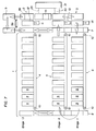
- the device essentially comprises a magazine 1, a emptying station 2, also called an adductor, a filling station 3, also called an extractor, and means for capturing information and order communications (not shown).
- the store 1 comprises an upper conveyor 4, an intermediate conveyor 5, a lower conveyor 6, a front lift 7 and a rear lift 8.
- the horizontal conveyors are conveyor belts having a width adapted to the width of the standard lockers 9 which will be placed on them with their rear wall arranged vertically on the side opposite stations 2 and 3. These bands are supported and driven by rollers 10 coupled, in a manner known per se, to motors (not shown).
- the various conveyors 4, 5 and 6 are superimposed and of the same length so as to be served by the elevators 7 and 8 which are placed at their two ends.
- a device designated by 11 capable of carrying out different movements of the lockers located either at the end of the conveyor 4 or on the elevator 7 , or in station 2.
- the device 11 can take a full locker located at the front end of the strip 4 and move it either on the elevator 7 at the level of the upper strip, or to the entrance 12 of station 2, where it is in the waiting position.
- the device 11 which is an auxiliary of the station 2 is also designed to move laterally, in the direction perpendicular to the drawing in FIG. 1 or vertically, or in another way, a rack which has emptied its load into the duct 15. At the same time, it can close the bottom wall of this rack.
- a new full rack can be moved synchronously from the standby position in the emptying station by the device 11.
- the empty rack pushed aside by the device 11 will for example be put on hold in a position spread laterally or vertically, then replaced on the elevator 7 and brought to the entrance of the filling station or on the conveyor 5.
- a device 13 similar to device 11, is placed at the level of the strip 5 to take one by one of the empty lockers 9 on the elevator 7 or on the anterior end of the strip 5 and introduce them, however without opening their wall lower, in the entry of the filling station 3.
- a third lateral displacement device 14 is placed at the level of the strip 6, under the device 13, that is to say between the elevator 7 and the station filling 3. It is intended to collect full lockers 9 in the outlet station (see fig. 2) of the filling station 3 and to move them in translation either on the elevator 7 or on the front end of the strip 6.
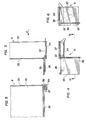
- the elevator 7, like the elevator 8, can be constructed as shown diagrammatically in FIG. 2.
- Two conveyor belts 16 and 17 are mounted vertically on rollers 18 having horizontal and parallel axes. From distance to distance, these bands carry supports 19 on which the lockers 9 can be engaged.
- the drive rollers 18 are controlled by sensors for the presence of a rack 9 on the supports 19 and for the height of the position of these supports.
- the emptying station or adductor 2 comprises a fixed support 22 intended to successively receive full lockers 9.
- the mechanism for opening the lower side wall of the locker placed on the support 22 will be activated once the presence locker at this location will have been detected.
- the two rigid elements of the support 22 are each connected by a segment of flexible strip 23 to one of the edges of the opening 20, so that the two segments 23 delimit with the anterior and posterior fixed walls 24 of the station 2 a hopper guiding the adduction of the rods in the conduit.
- Vibrators 25 ensure the introduction by acting on the strips 23.
- the filling station or extractor 3 also comprises two segments of flexible strips 26 connected to the two edges of the opening 21.
- the segments 26 are arranged so as to ensure progressive filling of an empty rack 9 having its side wall closed bottom, placed on a movable support 27, for example a horizontal plate fixed to the end of a rod 28 integral with the piston of a jack 29.
- Vibrators 30 control the vibrations and movements of the bands 26.
- An empty rack 9 from the conveyor 5 can be engaged on the walls 26 so as to rest on the plate 27 in the upper position, after which, as the plate 27 lowers, the sticks extracted from the conduit 15 through the opening 21, accumulate in the locker.
- the device 14 for lateral movement can convey it either to the elevator 7 or to the conveyor 6.
- a device 31 for driving the members 25 and 30 is also shown in FIG. 1.
- FIGS 3 to 6 show a possible embodiment of the lockers 9.
- Each of these comprises a rectangular rear wall 32 and two vertical side walls 33 rigidly fixed to the wall 32, extending in parallel and provided at their lower end d 'an internal rim 34.
- the rack has a third side wall 35 forming the bottom of the rack, each end of which is connected to one of the rims 34 by a linkage composed of two bars 36, 37, articulated one to the another and one of which is also articulated on the plate 35 and the other on one of the flanges 34.
- the control of the linkage for passing the opening bottom 35 from the position of figs. 3, 4, 5 at the position of fig. 6 can be provided by different means, for example jacks which can be associated with the supports 22 (see fig. 2).
- the control means of the linkage can also be of the electromagnetic type.
- the installation described has the great advantage of making it possible to manage the feeding of one or more machines at will, such as packers or assemblies.
- it has a large buffer in a reduced volume.
- the store can have any proportion of full and empty lockers. Any empty locker located on one of the conveyors can be brought to the inlet of the extractor and then once filled, reinserted in the store, without disturbing the operations in progress. Similarly, any full locker can be brought to the inlet of the adductor, and once emptied reinserted in the store. Feeding can be continuous or intermittent. Empty or full bins can also be entered manually or automatically from pallets.
- the elevator-descenders 7 and 8 can be arranged so that at least one of them has a loading station located at a level higher than that of the transporter 4 or at a level lower than that of the transporter 6.
- Managing the flow of rods can therefore be very flexible.
- the operations to be carried out to distribute the full and empty compartments on the carriers 4, 5 and 6 according to a judicious arrangement in the various situations which may arise can be programmed and controlled by computer.
- the management of the lockers does not require any turning or pivoting operation carried out on a pair of lockers and the movements are exclusively translations.
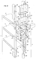
- FIGs. 7 and 8 show an alternative embodiment of the spacing device 11.
- a gripping means 38 cooperates with the adductor 2 so as to be able to grasp a rack 9 which has just been emptied and the raise vertically in a position such that the inlet 12 of the station 2 is released, so that a new full rack 9 can immediately be brought into the emptying position.
- a second auxiliary means represented at 39 then receives the raised locker 9 and transfers it to the upper position of the elevator 7. This empty locker can therefore be again moved down to the level of the bearing 5 and be put in stock on the conveyor belt of this bearing.
Landscapes
- Manufacturing Of Cigar And Cigarette Tobacco (AREA)
- Warehouses Or Storage Devices (AREA)
Applications Claiming Priority (2)
| Application Number | Priority Date | Filing Date | Title |
|---|---|---|---|
| CH1248/88 | 1988-04-05 | ||
| CH124888 | 1988-04-05 |
Publications (2)
| Publication Number | Publication Date |
|---|---|
| EP0336897A1 true EP0336897A1 (de) | 1989-10-11 |
| EP0336897B1 EP0336897B1 (de) | 1993-10-06 |
Family
ID=4205951
Family Applications (1)
| Application Number | Title | Priority Date | Filing Date |
|---|---|---|---|
| EP89810238A Expired - Lifetime EP0336897B1 (de) | 1988-04-05 | 1989-03-31 | Anlage zum Fördern von stabförmigen Artikeln |
Country Status (3)
| Country | Link |
|---|---|
| US (1) | US4995769A (de) |
| EP (1) | EP0336897B1 (de) |
| DE (1) | DE68909656T2 (de) |
Cited By (3)
| Publication number | Priority date | Publication date | Assignee | Title |
|---|---|---|---|---|
| WO1994013161A1 (de) * | 1992-12-15 | 1994-06-23 | Focke & Co. (Gmbh & Co.) | Speicher-einrichtung |
| EP0612481A3 (de) * | 1993-02-23 | 1994-10-26 | Focke & Co | Einrichtung zum Transport und zur Bevorratung von Zigaretten. |
| EP1752053A1 (de) * | 2005-08-09 | 2007-02-14 | G.D S.p.A. | Vorrichtung und Verfahren zum Speichern und zur Verfügungstellung von teilgefertigten Tabakprodukten |
Families Citing this family (13)
| Publication number | Priority date | Publication date | Assignee | Title |
|---|---|---|---|---|
| US5020965A (en) * | 1988-04-28 | 1991-06-04 | Kao Corporation | Method for shifting goods and apparatus therefor |
| DE3924098C2 (de) * | 1989-07-20 | 1998-05-20 | Hauni Werke Koerber & Co Kg | Behälterfördervorrichtung |
| US5350050A (en) * | 1993-09-09 | 1994-09-27 | Donald L. Collver | Continuous vertical conveyor |
| DE4404902C2 (de) * | 1994-02-16 | 2002-04-11 | Hauni Maschinenbau Ag | Verfahren und Einrichtung zur Handhabung von Zigarettenschragen aufnehmenden Containern |
| US6145577A (en) * | 1997-01-15 | 2000-11-14 | Hunter Automated Machinery Corporation | Linear mold handling system |
| US6571860B2 (en) | 1997-01-15 | 2003-06-03 | Hunter Automated Machinery Corporation | Two tiered linear mold handling systems |
| US5901774A (en) * | 1997-01-15 | 1999-05-11 | Hunter Automated Machinery Corporation | Linear mold handling system with double-deck pouring and cooling lines |
| KR100646620B1 (ko) * | 1999-05-06 | 2006-11-23 | 동경 엘렉트론 주식회사 | 유리 기판의 반송 시스템 |
| US6250454B1 (en) * | 1999-06-23 | 2001-06-26 | Danville Automation Holdings, Llc | Storage buffer for a multi lane conveyor |
| US20020025244A1 (en) * | 2000-04-12 | 2002-02-28 | Kim Ki-Sang | Transfer system and apparatus for workpiece containers and method of transferring the workpiece containers using the same |
| AU2003281528A1 (en) * | 2002-07-18 | 2004-02-09 | Fabio Perini S.P.A. | Storage unit for elongated products |
| ITFI20020219A1 (it) * | 2002-11-08 | 2004-05-09 | Perini Fabio | Magazzino polmone per tubi, specialmente tubi in cartone per la |
| HUE040438T2 (hu) * | 2016-09-28 | 2019-03-28 | Int Tobacco Machinery Poland Sp Zoo | Állomás rúdszerû árucikkekkel töltött tálcák számára és berendezés rúdszerû dohányipari árucikkekkel töltött tálcáknak az ürítésére |
Citations (2)
| Publication number | Priority date | Publication date | Assignee | Title |
|---|---|---|---|---|
| FR2139281A5 (de) * | 1971-05-07 | 1973-01-05 | Hauni Werke Koerber & Co Kg | |
| GB2142894A (en) * | 1983-07-06 | 1985-01-30 | Molins Plc | Conveying apparatus for rod-like articles |
Family Cites Families (11)
| Publication number | Priority date | Publication date | Assignee | Title |
|---|---|---|---|---|
| US2653723A (en) * | 1950-06-28 | 1953-09-29 | Arenco Ab | Supplying packing machine or the like with cigarettes |
| US2915022A (en) * | 1952-03-26 | 1959-12-01 | Entpr Railway Equipment Co | Hopper door operating mechanism for the discharge-outlet of railway hopper cars |
| US2753062A (en) * | 1952-08-04 | 1956-07-03 | Loudon Arthur | Transfer adaptor for cigarettes |
| GB1546794A (en) * | 1975-08-14 | 1979-05-31 | Molins Ltd | Apparatus for handling rod-like articles |
| IT1124149B (it) * | 1979-07-31 | 1986-05-07 | Cir Spa Divisione Sasib | Metodo e dispositivo per alimentare senza salti di livello cariche di oggetti astiformi ad una tramoggia di utilizzazione veloce continua |
| DE3278272D1 (en) * | 1982-03-31 | 1988-05-05 | Tabac Fab Reunies Sa | Device for supplying a machine with rigid elements |
| US4564329A (en) * | 1982-06-01 | 1986-01-14 | Hauni-Werke Korber & Co. Kg | Apparatus for manipulating empty and filled trays for cigarettes or the like between making and processing machines |
| ATE65888T1 (de) * | 1984-11-02 | 1991-08-15 | Tabac Fab Reunies Sa | Foerderanlage von stabfoermigen gegenstaenden zu einer verarbeitungsmaschine, insbesondere zu einer filteransetzmaschine. |
| GB8505804D0 (en) * | 1985-03-06 | 1985-04-11 | Molins Plc | Conveying apparatus |
| GB8519096D0 (en) * | 1985-07-29 | 1985-09-04 | Molins Plc | Conveyor system |
| US4892453A (en) * | 1986-07-17 | 1990-01-09 | Korber Ag | Apparatus for manipulating empty and filled trays for cigarettes and like rod-shaped articles between making and processing machines |
-
1989
- 1989-03-29 US US07/330,306 patent/US4995769A/en not_active Expired - Lifetime
- 1989-03-31 DE DE89810238T patent/DE68909656T2/de not_active Expired - Fee Related
- 1989-03-31 EP EP89810238A patent/EP0336897B1/de not_active Expired - Lifetime
Patent Citations (2)
| Publication number | Priority date | Publication date | Assignee | Title |
|---|---|---|---|---|
| FR2139281A5 (de) * | 1971-05-07 | 1973-01-05 | Hauni Werke Koerber & Co Kg | |
| GB2142894A (en) * | 1983-07-06 | 1985-01-30 | Molins Plc | Conveying apparatus for rod-like articles |
Cited By (5)
| Publication number | Priority date | Publication date | Assignee | Title |
|---|---|---|---|---|
| WO1994013161A1 (de) * | 1992-12-15 | 1994-06-23 | Focke & Co. (Gmbh & Co.) | Speicher-einrichtung |
| US5568856A (en) * | 1992-12-15 | 1996-10-29 | Focke & Co. (Gmbh & Co.) | Device for transporting and storing cigarettes |
| EP0612481A3 (de) * | 1993-02-23 | 1994-10-26 | Focke & Co | Einrichtung zum Transport und zur Bevorratung von Zigaretten. |
| US5567104A (en) * | 1993-02-23 | 1996-10-22 | Focke & Co. (Gmbh & Co.) | Apparatus for the transport and stocking of cigarettes |
| EP1752053A1 (de) * | 2005-08-09 | 2007-02-14 | G.D S.p.A. | Vorrichtung und Verfahren zum Speichern und zur Verfügungstellung von teilgefertigten Tabakprodukten |
Also Published As
| Publication number | Publication date |
|---|---|
| EP0336897B1 (de) | 1993-10-06 |
| US4995769A (en) | 1991-02-26 |
| DE68909656T2 (de) | 1994-05-11 |
| DE68909656D1 (de) | 1993-11-11 |
Similar Documents
| Publication | Publication Date | Title |
|---|---|---|
| EP0336897B1 (de) | Anlage zum Fördern von stabförmigen Artikeln | |
| EP0091058B1 (de) | Vorrichtung und Verfahren zum Lagern und/oder Ausspeichern von Gegenständen | |
| FR2499039A1 (fr) | Dispositif pour introduire des paquets de feuilles dans une machine les travaillant | |
| EP0294251A1 (de) | Automatische Verpackungsmaschine für Behälter | |
| EP1608470B1 (de) | Behältertransferanordnung für briefsortiermaschine | |
| WO2009071789A1 (fr) | Dispositif pour decharger des bacs par un organe pivotant | |
| FR2680121A1 (fr) | Module empileur pour machine de tri postal ou similaire. | |
| EP2796390B1 (de) | Automatisches transport- und lagersystem für produkte zur vorbereitung ihrer bestellungen und kontrollverfahren dieses systems | |
| JP4435172B2 (ja) | 物品で充填された及び/又は充填すべき容器の充填及び/又は排出をするための設備と容器を搬送するための操作装置 | |
| EP0429348A1 (de) | Vorrichtung zum Be- und/oder Entladen der Regale eines Gefriertrocknungsraumes | |
| FR2630094A1 (fr) | Dispositif pour transferer des barres d'une cassette a une table receptrice et pour reintroduire ces barres dans la cassette | |
| CA2695392C (fr) | Systeme de depose de documents dans des caisses | |
| EP0090124B1 (de) | Vorrichtung zum Zuführen von starren Elementen in eine Maschine | |
| EP0816267B1 (de) | Ejektor für gestapelte Gegenstände in Magazinen und automatisches Abgabesystem für Gegenstände aus Magazinen mittels einem Ejektor für Gegenstände aus Magazinen | |
| FR2517278A1 (fr) | Dispositif pour la mise en reserve de liasses formees de sacs empiles, pour l'alimentation d'un poste d'ensachage | |
| EP0277880B1 (de) | Beförderungsvorrichtung, insbesondere für Selbstbedienungsläden | |
| FR2562523A1 (fr) | Systeme de transfert d'objets entre deux dispositifs dont l'un comporte un ensemble de plateaux verticalement espaces | |
| EP1118556B1 (de) | Automatisches Verteilsystem für Gegenstände zum Kommissionieren einer oder mehrerer Bestellunguen | |
| EP0528736B1 (de) | Vorrichtung zum Transfer von Scheiben, insbesondere Silicon-Scheiben | |
| FR2462343A1 (fr) | Dispositif pour transferer a des receptacles disposes sur un transporteur continu des emballages ou piles de tels emballages contenus dans une goulotte d'alimentation | |
| EP1435197A1 (de) | Transportbehälter für Kleinvieh und Anlage zum Entladen in einem solchen Behälter | |
| FR2669312A1 (fr) | Magasin de stockage automatique. | |
| FR2565202A1 (fr) | Dispositif de preparation de commandes de produits groupes sous forme d'ensembles, en particulier de cigarettes | |
| FR2607116A1 (fr) | Magasin mecanise comprenant une pluralite de cellules de stockage d'articles | |
| FR2838114A1 (fr) | Ensemble de stockage, de triage et de preparation d'articles |
Legal Events
| Date | Code | Title | Description |
|---|---|---|---|
| PUAI | Public reference made under article 153(3) epc to a published international application that has entered the european phase |
Free format text: ORIGINAL CODE: 0009012 |
|
| AK | Designated contracting states |
Kind code of ref document: A1 Designated state(s): CH DE GB IT LI |
|
| 17P | Request for examination filed |
Effective date: 19891130 |
|
| 17Q | First examination report despatched |
Effective date: 19910830 |
|
| GRAA | (expected) grant |
Free format text: ORIGINAL CODE: 0009210 |
|
| AK | Designated contracting states |
Kind code of ref document: B1 Designated state(s): CH DE GB IT LI |
|
| REF | Corresponds to: |
Ref document number: 68909656 Country of ref document: DE Date of ref document: 19931111 |
|
| ITF | It: translation for a ep patent filed | ||
| GBT | Gb: translation of ep patent filed (gb section 77(6)(a)/1977) |
Effective date: 19931216 |
|
| PLBE | No opposition filed within time limit |
Free format text: ORIGINAL CODE: 0009261 |
|
| STAA | Information on the status of an ep patent application or granted ep patent |
Free format text: STATUS: NO OPPOSITION FILED WITHIN TIME LIMIT |
|
| 26N | No opposition filed | ||
| REG | Reference to a national code |
Ref country code: GB Ref legal event code: IF02 |
|
| PGFP | Annual fee paid to national office [announced via postgrant information from national office to epo] |
Ref country code: CH Payment date: 20020214 Year of fee payment: 14 |
|
| PGFP | Annual fee paid to national office [announced via postgrant information from national office to epo] |
Ref country code: GB Payment date: 20020220 Year of fee payment: 14 |
|
| PGFP | Annual fee paid to national office [announced via postgrant information from national office to epo] |
Ref country code: DE Payment date: 20020221 Year of fee payment: 14 |
|
| PG25 | Lapsed in a contracting state [announced via postgrant information from national office to epo] |
Ref country code: LI Free format text: LAPSE BECAUSE OF NON-PAYMENT OF DUE FEES Effective date: 20030331 Ref country code: GB Free format text: LAPSE BECAUSE OF NON-PAYMENT OF DUE FEES Effective date: 20030331 Ref country code: CH Free format text: LAPSE BECAUSE OF NON-PAYMENT OF DUE FEES Effective date: 20030331 |
|
| PG25 | Lapsed in a contracting state [announced via postgrant information from national office to epo] |
Ref country code: DE Free format text: LAPSE BECAUSE OF NON-PAYMENT OF DUE FEES Effective date: 20031001 |
|
| REG | Reference to a national code |
Ref country code: CH Ref legal event code: PL |
|
| GBPC | Gb: european patent ceased through non-payment of renewal fee |
Effective date: 20030331 |
|
| PG25 | Lapsed in a contracting state [announced via postgrant information from national office to epo] |
Ref country code: IT Free format text: LAPSE BECAUSE OF NON-PAYMENT OF DUE FEES Effective date: 20050331 |