EP0337006B1 - Rundballenpresse - Google Patents
Rundballenpresse Download PDFInfo
- Publication number
- EP0337006B1 EP0337006B1 EP88113183A EP88113183A EP0337006B1 EP 0337006 B1 EP0337006 B1 EP 0337006B1 EP 88113183 A EP88113183 A EP 88113183A EP 88113183 A EP88113183 A EP 88113183A EP 0337006 B1 EP0337006 B1 EP 0337006B1
- Authority
- EP
- European Patent Office
- Prior art keywords
- crop
- shaft
- machine according
- storage chamber
- web
- Prior art date
- Legal status (The legal status is an assumption and is not a legal conclusion. Google has not performed a legal analysis and makes no representation as to the accuracy of the status listed.)
- Expired
Links
- 230000007246 mechanism Effects 0.000 claims description 22
- 239000000463 material Substances 0.000 claims description 16
- 230000002441 reversible effect Effects 0.000 claims description 2
- 125000006850 spacer group Chemical group 0.000 claims 3
- 208000028659 discharge Diseases 0.000 description 6
- 230000015572 biosynthetic process Effects 0.000 description 2
- 238000000034 method Methods 0.000 description 1
- 238000011144 upstream manufacturing Methods 0.000 description 1
Images


Classifications
-
- A—HUMAN NECESSITIES
- A01—AGRICULTURE; FORESTRY; ANIMAL HUSBANDRY; HUNTING; TRAPPING; FISHING
- A01F—PROCESSING OF HARVESTED PRODUCE; HAY OR STRAW PRESSES; DEVICES FOR STORING AGRICULTURAL OR HORTICULTURAL PRODUCE
- A01F15/00—Baling presses for straw, hay or the like
- A01F15/07—Rotobalers, i.e. machines for forming cylindrical bales by winding and pressing
- A01F15/0705—Arrangements for continuous operation
Definitions
- This invention relates to a machine for forming bales of crop having a baling chamber, a forward storage chamber, and a unit for delivering crop selectively to the baling or storage chamber in which the storage chamber is delimited in its lower part by belt material including a portion located for receiving crop thereon from the delivery unit.
- Machines towed by a tractor, for forming large cylindrical bales of hay (so called "round balers") are well known. As the machine advances, the crop is removed from a windrow by a pick-up mechanism and delivered rearwardly to a baling chamber where it is rolled into a bale.
- the chamber In one type of machine the chamber is defined by runs of belts trained over driven rolls, whilst in another type fixed position rolls form the chamber.
- bale On completion a bale is tied with twine wrapped round it to maintain the crop within the bale, a gate formed by the rear portion of the machine is opened and the bale is discharged. During this period the machine is stationary since crop can no longer be delivered to the baling chamber.
- the storage chamber is designed as a small baling chamber and delimited at its lower part by a part of a conveyor belt.
- a passage between the storage chamber and the baling chamber will be produced by raising an intermediate roller and belt device. This passage permits a transfer of a bale core formed in the storage chamber into the baling chamber under the conveying action produced by the conveyor belt and due to the fact that the belt core is no longer held back by the runs of the belt device.
- the roller and belt device is lowered into an intermediate position and the conveyor belt is itself lowered by pivoting it about its rear return roller, whereby a front mounted pick-up pivots slightly upwardly with respect to the conveyor belt.
- a front mounted pick-up pivots slightly upwardly with respect to the conveyor belt.
- a known procedure for collecting, loading and unloading crop makes use of a winder mechanism arranged on a wagon. Crop is collected from the ground by a pick-up and conveyed through a swingable spout having internal conveyor means to a rotatable non-drivable coiling beam.
- the coiling beam is provided with a radial offset and coupled to one end of a web of belting material wrapped upon a support shaft.
- the support shaft is rotatably connected to the ends of swing arms.
- the web is guided on top of the spout and compressed crop delivered by the conveyor inside the spout contacts the radial offset of the coiling beam and rotates the coiling beam such that the web will be coiled into a spiral thereby sandwiching the crop in the spiral.
- For unloading the crop spiral in uncoiled by manually rotating the bale together with the support shaft by more than 180 ° into an unloading position and by switching on a drive for the support shaft.
- the object of the present invention is to provide a mainly "non-stop" round baler which is less expensive and yet which offers good crop control.
- the storage chamber has a winder mechanism comprising: a position fixed belt support shaft with said belt material wrapped upon it, extending transversely across said storage chamber, drivable in one direction and rotatable in the opposite direction; and a coiling shaft extending across said storage chamber in spaced relationship to said support shaft, receiving one end of said belt material and drivable in one direction and rotatable in the opposite direction wherein the drives for the shafts are arranged such that the coiling shaft is drivable for conveying crop from the delivery unit to the storage chamber where the belt material is coiled into a spiral and the crop is sandwiched in the spiral for storage and that the support shaft is drivable for uncoiling the belt material and the crop, so that the crop is released and conveyed by the belt material to the baling chamber.
- the machine for working without stopping during tying and discharge of a completed bale has a very simple storage chamber by using a winder mechanism drivable for coiling the belt material into a spiral so that the crop is sandwiched and stored in the spiral, for uncoiling the belt material so that the crop is released for delivery, for conveying crop from the delivery unit to the storage area and for conveying uncoiled crop from the storage area to the baling chamber.
- a winder mechanism drivable for coiling the belt material into a spiral so that the crop is sandwiched and stored in the spiral, for uncoiling the belt material so that the crop is released for delivery, for conveying crop from the delivery unit to the storage area and for conveying uncoiled crop from the storage area to the baling chamber.
- crop In the storing position crop is contained between layers of web and in the conveying position crop is contained on top of a layer of web.
- the crop is well controlled in its various positions.
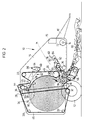
- the baler includes a main frame 10 mounted on a pair of wheels 12.
- the main frame has an upright fore-and-aft extending wall 14 on either side, connected by transverse beams, e.g. front beam 15.
- a draft tongue 16 is connected to a transverse beam at the front of the frame 10 and extends forwardly for attaching the baler to a tractor (also not shown) which draws the machine.
- a plurality of lateral rolls extends over the width of the machine.
- One set of rolls 18, 19, 20, 22, 24 is journalled in the side walls 14, whilst another set consisting of rolls 26, 28, 30, 32 is journalled in a gate 34 which is swingable about a pivot 36 at the top of the baler.
- Six rubber belts 46 are trained side-by-side over the rolls, with the exception of the rolls 18, 19 which act as stripper and feed rolls respectively, to provide the configuration shown and they move in the direction indicated by arrows 48, the rolls 18, 19 being driven anti-clockwise as viewed in the Figures.
- An auger 49 is associated with the roll 20, extending therealong and through the side walls 14, to carry away crop debris which tends to become trapped in this region.
- Upwardly extending runs 50, 52 of the belts 46 define a bale-forming chamber 54 the ends of which are provided by the side walls 14 and the gate 34 and which has an inlet 56 for crop received from a pick-up 58 beneath it.
- a belt take-up and tensioning mechanism is provided at either side of the machine.
- These mechanisms include a pair of rearwardly extending idler arms which are mounted on the main frame 10 by way of a horizontal transverse shaft 60, providing a pivot connection for the arms, and of which the right hand arm 62 only is shown; the belt take-up roll 42 which is supported at either end at an intermediate location on the arms; and the pair of chamber restricting rolls 38, 40 supported at the free ends of the arms.
- the arms are biased in an anti-clockwise direction in the Figures.
- a lever portion 64 which is rigid with the pivot shaft 60 is pivotally connected at a point 66 to the cylinder of a piston and cylinder unit indicated by line 68, loading the arm 62, of which the piston is in turn pivotally connected to the gate 34 at a point 70, a similar arrangement being provided also on the left hand side of the machine.
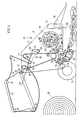
- the walls 14 have forwardly extending portions to encompass a crop storage chamber or region 71. Between these portions is a roll of a web of conveyor belting 72 the inner end of which is attached to a transverse uncoiling shaft 74 which carries the roll and which is disposed just behind the rear end of the tongue 16.
- An idler roll 76 is also mounted between the walls 14 above the pick-up 58 approximately level with the shaft 74 and is disposed intermediate the shaft 74 and a coiling shaft 78 approximately level with the top of the baling chamber 54 in Fig. 1 which shaft 78 again is mounted between the walls 14.
- the coiling shaft 78 has three plates 80, 82, 84 rigidly attached to it along its length which extend radially outwardly therefrom at 120° intervals round the shaft.
- the belting 72 is trained over the idler roll 76 and its end is attached to the radially outer lengthwise edge of the plate 84.
- Both the shafts 74 and 78 are drivable from the main drive of the machine via an electrical or similar clutch (not shown).
- the shaft 78 can be driven in an anti-clockwise "coiling” direction and the shaft 74 in an anti-clockwise "uncoiling” direction whilst the associated shaft 74, 78 respectively idles but is restrained somewhat from entirely free rotation by being braked or by being slowed frictionally thereby maintaining the belting 72 in tension.
- the terms “coiling” and “uncoiling” are explained below when the operation of the machine is described.
- the pick-up 58 works on a windrow 86 of hay and extends rearwardly and upwardly at a small angle.
- a feeder fork mechanism 88 is disposed at the rearward downstream end of the pick-up 58, is angled more steeply upwardly and terminates at the roll 19 at the inlet 56 of the baling chamber 54.
- This mechanism 88 is of conventional design with a crankshaft driving a feeder fork, prongs 89 of which extend into gaps between neighbouring side-by-side strippers which support the crop. Drive to the crank shaft is transmitted through a clutch.
- the pick-up 58 and the mechanism 88 constitute a crop delivery unit.
- baling chamber 54 expands against the loaded idler arms as the bale 90 grows in size until the bale is completed Fig. 2) whereupon crop flow to the inlet 54 by the feeder fork mechanism 88 is stopped and the bale 90 is tied with twine and as shown in Fig. 3 is finally discharged by swinging the gate 34 upwardly.
- the feeder fork mechanism 88 is stopped by disengaging the clutch in the drive thereto and set with its fork prongs 89 at an angle (shown in Fig.2) which is such that the crop will divert in its course to the flow path between the rolls 20 and 76, only the still functioning pick-up 58 endowing the crop with its movement.
- the same result can be obtained, without disengaging the feeder fork, by mounting the strippers in cantilever fashion on a shaft pivoting at the downstream end of the pick-up 58 enabling them to be set,when required, at an appropriate angle to divert the crop.
- the crop is fed onto a run 92 of the belting 72 between the roll 76 and the plate 84.
- the coiling shaft 78 is then driven anti-clockwise as in Fig. 3 causing the belting 72 to be turned in the "coiling" direction to form a spiral 94 with the crop packed between the layers of belting, the plates 80, 82, 84 serving to space the belting 72 away from the shaft 78 and initially to sweep the crop into the incipient spiral. In this way incoming crop is stored during tying and discharge of the bale 90.
- baling commences again as in Fig. 4, the drive to the coiling shaft 78 is cut and then the drive to the uncoiling shaft 74 is engaged to drive it anti-clockwise in the "uncoiling" direction.
- Guides or a reversible feeder fork apparatus can be positioned above the run 92 in front of the roll 20 to prevent contact during uncoiling between the crop and the belts 46.
- the cycle is repeated and it is generally unnecessary to break the continuous progress of the baler along the windrow 86.
- a logical electronic circuit can control the cycle and the sequence can be displayed on a monitor in the cab of the tractor drawing the baler.
- a signal can be provided to inform the operator that the storage capacity of the belting 72 is approaching its peak. In this event the operator can reduce speed or stop until the bale 90 has been discharge and the gate 34 is again closed.
- the uncoiling shaft 74, the idler roll 76, and the coiling shaft 78 with its plates 80, 82, 84 constitute a "winder mechanism" for the web of belting 72.
- the belting 72 and winder mechanism are not expensive and yet the crop is well controlled during storage and during feeding from storage in that it is confined between layers of the belting.
- the winder mechanism and web can also be used in balers with fixed position rolls defining the baling chamber.
- a web comprising of several belts side-by-side can be used.
- the web can be in the form of rubber belting generally similar to that of the baling belts 46 but it can also, for example, be woven or other suitable sheeting.
Landscapes
- Life Sciences & Earth Sciences (AREA)
- Environmental Sciences (AREA)
- Storage Of Harvested Produce (AREA)
Claims (11)
- Maschine zum Formen von Erntegutballen (90) mit einer Ballenformkammer (54), einer vorderen Speicherkammer (71) und einer Einheit (58,88), um das Erntegut selektiv in die Ballenform- (54) oder die Speicherkammer (71) zu liefern, bei der die Speicherkammer (71) in ihrem unteren Bereich durch Bandmaterial einschließlich eines Abschnittes begrenzt ist, der so angeordnet ist, daß er des Erntegut von der Zuliefereinheit (55,88) auf diesem Abschnitt aufnimmt, dadurch gekennzeichnet, daß die Speicherkammer (71) einen Aufwickelmechanismus aufweist, der umfaßt: eine ortsfeste Bandstützwelle (74), auf der das genannte Bandmaterial aufgewickelt ist, die sich quer durch die Speicherkammer (71) erstreckt, in einer Richtung antreibbar und in der Gegenrichtung drehbar ist; und eine Wickelwelle (78), die sich quer durch die genannte Speicherkammer (71) im Abstand zu der genannten Stützwelle (74) erstreckt, ein Ende des genannten Bandmaterials aufnimmt und in einer Richtung antreibbar und in der Gegenrichtung drehbar ist, wobei die Antriebe für die Wellen (74,78) so angeordnet sind, daß die Wickelwelle (78) für das Fördern des Erntegutes von der Zuliefereinheit in die Speicherkammer (71) antreibbar ist, in welcher das Bandmaterial spiralförmig aufgewickelt und das Erntegut in der Spirale zu Speicherzwekken geschichtet ist, während die Stützwelle (74) zum Abwickeln des Bandes und des Erntegutes antreibbar ist, so daß das Erntegut freigegeben und durch das Bandmaterial in die Ballenformkammer (54) gefördert wird.
- Maschine nach Anspruch 1, dadurch gekennzeichnet, daß die Wickelwelle (78) mit dem genannten einen Ende der Bahn (72) oder des Bandmaterials über eine Verankerungsplatte (84) verbunden ist, welche sich von der Welle nach außen erstreckt, wobei ein innerer Kantenbereich der Platte mit der Welle (78) starr verbunden ist, während ein äußerer Kantenbereich der Platte an dem genannten einen Ende der Bahn (72) angebracht ist.
- Maschine nach Anspruch 2, dadurch gekennzeichnet, daß die Ebene der Verankerungsplatte (84) gegenüber der Wickelwelle (78) radial verläuft.
- Maschine nach Anspruch 2 oder 3, dadurch gekennzeichnet, daß eine Abstandsplatte oder mehrere solche Platten (80,82) sich von der Wickelwelle (78) nach außen erstrecken, ein innerer Kantenbereich der Abstandsplatte oder Platten (80,82) starr an der Wickelwelle (78) angebracht ist und daß die Verankerungs- und Abstandsplatte (84,80,82) um die Wickelwelle (78) in Abständen angeordnet sind.
- Maschine nach irgendeinem der Ansprüche 2 bis 4, dadurch gekennzeichnet, daß der Aufwickelmechanismus eine Zwischenrolle (76) aufweist, die zwischen der aufwickelnden und der abwickelnden Welle (78,74) angeordnet und über die die Bahn (72) gezogen ist.
- Maschine nach irgendeinem der voranstehenden Ansprüche, bei der die Zuliefereinheit eine Pick-up-Vorrichtung (58) aufweist, dadurch gekennzeichnet, daß die Zuliefereinheit einen zur Zuführung dienenden Gabelmechanismus (88) an seinem stromabwärts liegenden Ende aufweist.
- Maschine nach Anspruch 5 und 6, in der die Ballenformkammer (54) ihren Einlaß (56) für den Eintritt des Erntegutes auf der Unterseite der Maschine aufweist, dadurch gekennzeichnet, daß die Abwickelwelle (74) sich am Frontbereich der Maschine befindet, die Zwischenrolle (76) über der Pick-up-Vorrichtung (58) angeordnet ist und die Wickelwelle (78) sich auf einem Niveau oberhalb der Zwischenrolle (76) und der Abwickelwelle (74) befindet.
- Maschine nach Anspruch 6 oder 7, dadurch gekennzeichnet, daß der gabelförmige Gabelmechanismus (88) eine Zuführungsgabel, eine Kurbelwelle zum Antreiben der Zuführungsgabel und Abstreifelemente zum Unterstützen des Erntegutes aufweist, welche Abstreifelemente am stromabwärtsliegenden Ende der Pick-up-Vorrichtung (58) montiert sind, so daß sie zwischen einer Abstreifstellung und einer Stellung schwenkbar sind, in der sie das Erntegut der Speicherkammer (71) zuleiten.
- Maschine nach irgendeinem der voranstehenden Ansprüche, dadurch gekennzeichnet, daß die Bahn ein einzelnes Förderband (72) umfaßt.
- Maschine nach irgendeinem der Ansprüche 1 bis 7, dadurch gekennzeichnet, daß die Bahn (72) aus einer Mehrzahl von Seite an Seite angeordneten Förderbändern besteht.
- Maschine nach irgendeinem der voranstehenden Ansprüche, dadurch gekennzeichnet, daß eine Erntegutführungseinrichtung oder eine zur Zuführung dienende umkehrbare Gabeleinrichtung oberhalb der Bahn (72) angeordnet ist.
Applications Claiming Priority (2)
| Application Number | Priority Date | Filing Date | Title |
|---|---|---|---|
| GB8808468 | 1988-04-11 | ||
| GB8808468A GB2217253B (en) | 1988-04-11 | 1988-04-11 | Baling machine for forming cylindrical bales of crop |
Publications (2)
| Publication Number | Publication Date |
|---|---|
| EP0337006A1 EP0337006A1 (de) | 1989-10-18 |
| EP0337006B1 true EP0337006B1 (de) | 1992-05-20 |
Family
ID=10634956
Family Applications (1)
| Application Number | Title | Priority Date | Filing Date |
|---|---|---|---|
| EP88113183A Expired EP0337006B1 (de) | 1988-04-11 | 1988-08-13 | Rundballenpresse |
Country Status (5)
| Country | Link |
|---|---|
| US (1) | US4914900A (de) |
| EP (1) | EP0337006B1 (de) |
| CA (1) | CA1322695C (de) |
| DE (1) | DE3871376D1 (de) |
| GB (1) | GB2217253B (de) |
Families Citing this family (26)
| Publication number | Priority date | Publication date | Assignee | Title |
|---|---|---|---|---|
| US5080009A (en) * | 1990-10-04 | 1992-01-14 | Hay & Forage Industries | Round baler having trash discharge mechanism |
| DE4031590C1 (de) * | 1990-10-05 | 1991-12-05 | Deere & Co., Moline, Ill., Us, Niederlassung Deere & Co. European Office, 6800 Mannheim, De | |
| US6263650B1 (en) | 1999-09-23 | 2001-07-24 | Deere & Company | Cotton harvester with accumulator |
| EP2220929A1 (de) | 2009-02-21 | 2010-08-25 | Deere & Company | Rundballenpresse |
| US8490375B2 (en) | 2009-07-31 | 2013-07-23 | Agco Corporation | Baler collector for collecting biomass from a combine harvester |
| US8291687B2 (en) * | 2009-07-31 | 2012-10-23 | Agco Corporation | Continuous round baler |
| US8413414B2 (en) * | 2009-07-31 | 2013-04-09 | Agco Corporation | Continuous round baler with accumulation conveyor |
| US8464508B2 (en) * | 2009-07-31 | 2013-06-18 | Agco Corporation | Biomass baler |
| US20110024538A1 (en) * | 2009-07-31 | 2011-02-03 | Agco Corporation | Combine Chopper For Feeding A Baler |
| US8443580B2 (en) * | 2009-07-31 | 2013-05-21 | Agco Corporation | Baler pickup for collecting biomass from a combine harvester |
| EP2281437B1 (de) * | 2009-08-03 | 2013-01-09 | Deere & Company | Rundballenpresse |
| NL1037435C2 (en) | 2009-11-02 | 2011-05-03 | Lely Patent Nv | Baling device to form bales of crop material. |
| US8733241B2 (en) | 2012-05-15 | 2014-05-27 | Cnh Industrial Canada, Ltd. | Continuous round baler chambers and conveyor system |
| US9084394B2 (en) | 2013-02-22 | 2015-07-21 | CNH Industrial Canada, LTD | Continuous crop accumulator for agricultural harvesters |
| US9918433B2 (en) * | 2014-06-26 | 2018-03-20 | Cnh Industrial Canada, Ltd. | Continuous harvester and mobile wrapping systems and methods of using the same |
| US9510511B2 (en) * | 2015-04-16 | 2016-12-06 | Deere & Company | Rotary brush for cleaning round module builder belts |
| US9894843B2 (en) * | 2016-01-14 | 2018-02-20 | Cnh Industrial America Llc | Continuous harvester with crop supply chamber |
| US9877432B2 (en) * | 2016-01-14 | 2018-01-30 | Cnh Industrial America Llc | Continuous harvester with crop supply chamber |
| US9949438B2 (en) * | 2016-01-14 | 2018-04-24 | Cnh Industrial America Llc | Continuous harvester with crop supply chamber |
| US10111389B2 (en) * | 2016-05-04 | 2018-10-30 | Deere & Company | Non-stop baling system |
| US11382275B2 (en) | 2016-08-31 | 2022-07-12 | Tube-Line Manufacturing Limited | Continuous round baler accumulation chamber |
| PL3672393T3 (pl) * | 2017-08-21 | 2026-01-19 | Kverneland Group Ravenna S.R.L. | Sposób obsługi prasy belującej oraz prasa belująca |
| US10986785B2 (en) * | 2018-06-26 | 2021-04-27 | Cnh Industrial America Llc | Continuous round baler and methods of using the same |
| WO2021163195A1 (en) * | 2020-02-12 | 2021-08-19 | Cnh Industrial Canada, Ltd. | Accumulating system for an agricultural system |
| DE102022112955A1 (de) * | 2022-05-23 | 2023-11-23 | Maschinenfabrik Bernard Krone GmbH & Co. KG | Rundballenpresse |
| DE102022112958A1 (de) * | 2022-05-23 | 2023-11-23 | Maschinenfabrik Bernard Krone GmbH & Co. KG | Rundballenpresse |
Family Cites Families (13)
| Publication number | Priority date | Publication date | Assignee | Title |
|---|---|---|---|---|
| DE1757733A1 (de) * | 1968-06-08 | 1971-05-19 | Josef Duecker | Verfahren zum Aufnehmen,Laden und Entladen von halm- oder blattartigem landwirtschaftlichen Erntegut und Vorrichtung zur Durchfuehrung des Verfahrens |
| US4296595A (en) * | 1978-07-27 | 1981-10-27 | M & W Gear Company | Apparatus for wrapping a cover material around round bales |
| DE3151580A1 (de) * | 1981-12-28 | 1983-07-07 | Claas Ohg, 4834 Harsewinkel | Rundballengrosspresse |
| EP0159983A1 (de) * | 1982-12-17 | 1985-11-06 | WEBB, Dennis Leslie | Verfahren zum erzeugen runder ballen |
| DE3311132A1 (de) * | 1983-03-26 | 1984-09-27 | Claas Ohg, 4834 Harsewinkel | Vorrichtung zum aufwickeln und umhuellen eines zylinderischen erntegutballens |
| DE3311330C2 (de) * | 1983-03-29 | 1986-10-30 | Claas Ohg, 4834 Harsewinkel | Verfahren und Vorrichtung zum Aufwickeln und Umhüllen eines zylindrischen Erntegutballens |
| US4534285A (en) * | 1983-11-29 | 1985-08-13 | Sperry Corporation | Actuator mechanism for continuous roll baling machine |
| EP0149368B1 (de) * | 1984-01-19 | 1988-06-15 | JOHN DEERE (Société Anonyme) | Rundballenpresse |
| US4542617A (en) * | 1984-06-12 | 1985-09-24 | Patrick Sonntag | Baling machine |
| GB8423231D0 (en) * | 1984-09-14 | 1984-10-17 | Multinorm Bv | Agricultural baler |
| GB2169847A (en) * | 1985-01-15 | 1986-07-23 | William Andrew Scorgie | Apparatus for forming bales |
| DE3710550C1 (de) * | 1987-03-30 | 1988-06-30 | Zweegers & Zonen P J | Rollballenpresse fuer Erntegut |
| DE3734850A1 (de) * | 1987-10-14 | 1989-04-27 | Zweegers & Zonen P J | Verfahren zum herstellen von erntegut-rollballen sowie vorrichtung zum durchfuehren des verfahrens |
-
1988
- 1988-04-11 GB GB8808468A patent/GB2217253B/en not_active Expired - Lifetime
- 1988-08-13 DE DE8888113183T patent/DE3871376D1/de not_active Expired - Lifetime
- 1988-08-13 EP EP88113183A patent/EP0337006B1/de not_active Expired
-
1989
- 1989-04-06 US US07/334,615 patent/US4914900A/en not_active Expired - Fee Related
- 1989-04-11 CA CA000596312A patent/CA1322695C/en not_active Expired - Fee Related
Also Published As
| Publication number | Publication date |
|---|---|
| GB2217253A (en) | 1989-10-25 |
| GB2217253B (en) | 1992-05-27 |
| DE3871376D1 (de) | 1992-06-25 |
| EP0337006A1 (de) | 1989-10-18 |
| US4914900A (en) | 1990-04-10 |
| CA1322695C (en) | 1993-10-05 |
| GB8808468D0 (en) | 1988-05-11 |
Similar Documents
| Publication | Publication Date | Title |
|---|---|---|
| EP0337006B1 (de) | Rundballenpresse | |
| US6651418B1 (en) | Modular pickup, stuffer, and rotor | |
| CA2870872C (en) | Continuous bale forming apparatus with a reciprocating bale pushing device | |
| EP0252485A1 (de) | Rollballenpresse für landwirtschaftliches Erntegut | |
| US4597254A (en) | Continuous roll baler | |
| US4470247A (en) | Round bale forming machine | |
| US5036642A (en) | Bale wrapping apparatus for round balers | |
| US5598690A (en) | Tailgate latching apparatus for a round baler | |
| GB2090560A (en) | Agricultural baling machine | |
| US4158331A (en) | Center pivot dispensing apparatus | |
| US5802825A (en) | Method and apparatus for controlling round bale cutter | |
| EP0235787B1 (de) | Maschine zur Bildung von Rundballen | |
| US5184545A (en) | Round baler twine wrapping apparatus | |
| WO2011033494A1 (en) | A baler | |
| EP0766912B1 (de) | Maschine und Verfahren um Rundballen zu Umhüllen | |
| US4813348A (en) | Machine for forming cylindrical bales of crop | |
| EP0316506B1 (de) | Rundballenmaschine | |
| US5419108A (en) | Method of forming a segmented round bale | |
| US5465658A (en) | Twine cutting apparatus for round baler | |
| US4597249A (en) | Method of forming roll bales | |
| US5447022A (en) | Crop cutting apparatus for a round baler | |
| US4242857A (en) | Override means for automatic bale ejection drive | |
| US5437226A (en) | Twine cutter for a round baler | |
| EP0680689B1 (de) | Bindegarn-Schneidvorrichtung für eine Rundballenpresse | |
| EP0681782B1 (de) | Verfahren und Vorrichtung um einen geschnittenen Rundballen zu formen |
Legal Events
| Date | Code | Title | Description |
|---|---|---|---|
| PUAI | Public reference made under article 153(3) epc to a published international application that has entered the european phase |
Free format text: ORIGINAL CODE: 0009012 |
|
| AK | Designated contracting states |
Kind code of ref document: A1 Designated state(s): DE ES FR GB IT NL |
|
| 17P | Request for examination filed |
Effective date: 19900307 |
|
| 17Q | First examination report despatched |
Effective date: 19910426 |
|
| ITF | It: translation for a ep patent filed | ||
| GRAA | (expected) grant |
Free format text: ORIGINAL CODE: 0009210 |
|
| AK | Designated contracting states |
Kind code of ref document: B1 Designated state(s): DE ES FR GB IT NL |
|
| PG25 | Lapsed in a contracting state [announced via postgrant information from national office to epo] |
Ref country code: ES Free format text: THE PATENT HAS BEEN ANNULLED BY A DECISION OF A NATIONAL AUTHORITY Effective date: 19920520 |
|
| REF | Corresponds to: |
Ref document number: 3871376 Country of ref document: DE Date of ref document: 19920625 |
|
| ET | Fr: translation filed | ||
| PLBE | No opposition filed within time limit |
Free format text: ORIGINAL CODE: 0009261 |
|
| STAA | Information on the status of an ep patent application or granted ep patent |
Free format text: STATUS: NO OPPOSITION FILED WITHIN TIME LIMIT |
|
| 26N | No opposition filed | ||
| PGFP | Annual fee paid to national office [announced via postgrant information from national office to epo] |
Ref country code: GB Payment date: 19940708 Year of fee payment: 7 |
|
| PG25 | Lapsed in a contracting state [announced via postgrant information from national office to epo] |
Ref country code: GB Effective date: 19950813 |
|
| GBPC | Gb: european patent ceased through non-payment of renewal fee |
Effective date: 19950813 |
|
| PGFP | Annual fee paid to national office [announced via postgrant information from national office to epo] |
Ref country code: NL Payment date: 20050716 Year of fee payment: 18 |
|
| PGFP | Annual fee paid to national office [announced via postgrant information from national office to epo] |
Ref country code: FR Payment date: 20050817 Year of fee payment: 18 |
|
| PGFP | Annual fee paid to national office [announced via postgrant information from national office to epo] |
Ref country code: DE Payment date: 20050831 Year of fee payment: 18 |
|
| PG25 | Lapsed in a contracting state [announced via postgrant information from national office to epo] |
Ref country code: NL Free format text: LAPSE BECAUSE OF NON-PAYMENT OF DUE FEES Effective date: 20070301 Ref country code: DE Free format text: LAPSE BECAUSE OF NON-PAYMENT OF DUE FEES Effective date: 20070301 |
|
| NLV4 | Nl: lapsed or anulled due to non-payment of the annual fee |
Effective date: 20070301 |
|
| REG | Reference to a national code |
Ref country code: FR Ref legal event code: ST Effective date: 20070430 |
|
| PGFP | Annual fee paid to national office [announced via postgrant information from national office to epo] |
Ref country code: IT Payment date: 20070830 Year of fee payment: 20 |
|
| PG25 | Lapsed in a contracting state [announced via postgrant information from national office to epo] |
Ref country code: FR Free format text: LAPSE BECAUSE OF NON-PAYMENT OF DUE FEES Effective date: 20060831 |