EP0337096A1 - Détecteur modulaire pour une caméra à scintillation - Google Patents
Détecteur modulaire pour une caméra à scintillation Download PDFInfo
- Publication number
- EP0337096A1 EP0337096A1 EP89103518A EP89103518A EP0337096A1 EP 0337096 A1 EP0337096 A1 EP 0337096A1 EP 89103518 A EP89103518 A EP 89103518A EP 89103518 A EP89103518 A EP 89103518A EP 0337096 A1 EP0337096 A1 EP 0337096A1
- Authority
- EP
- European Patent Office
- Prior art keywords
- scintillator
- strips
- scintillation
- detector module
- scintillator strips
- Prior art date
- Legal status (The legal status is an assumption and is not a legal conclusion. Google has not performed a legal analysis and makes no representation as to the accuracy of the status listed.)
- Ceased
Links
- 239000000463 material Substances 0.000 claims description 14
- 238000012856 packing Methods 0.000 abstract description 4
- 239000013078 crystal Substances 0.000 description 5
- 230000005855 radiation Effects 0.000 description 3
- 230000000694 effects Effects 0.000 description 2
- 238000011835 investigation Methods 0.000 description 1
- 239000011159 matrix material Substances 0.000 description 1
- 238000000034 method Methods 0.000 description 1
- 238000012544 monitoring process Methods 0.000 description 1
- 238000009206 nuclear medicine Methods 0.000 description 1
- 238000003325 tomography Methods 0.000 description 1
Images
Classifications
-
- G—PHYSICS
- G01—MEASURING; TESTING
- G01T—MEASUREMENT OF NUCLEAR OR X-RADIATION
- G01T1/00—Measuring X-radiation, gamma radiation, corpuscular radiation, or cosmic radiation
- G01T1/16—Measuring radiation intensity
- G01T1/161—Applications in the field of nuclear medicine, e.g. in vivo counting
- G01T1/164—Scintigraphy
- G01T1/1641—Static instruments for imaging the distribution of radioactivity in one or two dimensions using one or several scintillating elements; Radio-isotope cameras
- G01T1/1642—Static instruments for imaging the distribution of radioactivity in one or two dimensions using one or several scintillating elements; Radio-isotope cameras using a scintillation crystal and position sensing photodetector arrays, e.g. ANGER cameras
-
- G—PHYSICS
- G01—MEASURING; TESTING
- G01T—MEASUREMENT OF NUCLEAR OR X-RADIATION
- G01T1/00—Measuring X-radiation, gamma radiation, corpuscular radiation, or cosmic radiation
- G01T1/16—Measuring radiation intensity
- G01T1/161—Applications in the field of nuclear medicine, e.g. in vivo counting
- G01T1/164—Scintigraphy
- G01T1/1641—Static instruments for imaging the distribution of radioactivity in one or two dimensions using one or several scintillating elements; Radio-isotope cameras
- G01T1/1644—Static instruments for imaging the distribution of radioactivity in one or two dimensions using one or several scintillating elements; Radio-isotope cameras using an array of optically separate scintillation elements permitting direct location of scintillations
-
- G—PHYSICS
- G01—MEASURING; TESTING
- G01T—MEASUREMENT OF NUCLEAR OR X-RADIATION
- G01T1/00—Measuring X-radiation, gamma radiation, corpuscular radiation, or cosmic radiation
- G01T1/16—Measuring radiation intensity
- G01T1/20—Measuring radiation intensity with scintillation detectors
- G01T1/2008—Measuring radiation intensity with scintillation detectors using a combination of different types of scintillation detectors, e.g. phoswich
-
- G—PHYSICS
- G01—MEASURING; TESTING
- G01T—MEASUREMENT OF NUCLEAR OR X-RADIATION
- G01T1/00—Measuring X-radiation, gamma radiation, corpuscular radiation, or cosmic radiation
- G01T1/16—Measuring radiation intensity
- G01T1/20—Measuring radiation intensity with scintillation detectors
- G01T1/2018—Scintillation-photodiode combinations
- G01T1/20182—Modular detectors, e.g. tiled scintillators or tiled photodiodes
-
- G—PHYSICS
- G01—MEASURING; TESTING
- G01T—MEASUREMENT OF NUCLEAR OR X-RADIATION
- G01T1/00—Measuring X-radiation, gamma radiation, corpuscular radiation, or cosmic radiation
- G01T1/16—Measuring radiation intensity
- G01T1/20—Measuring radiation intensity with scintillation detectors
- G01T1/2018—Scintillation-photodiode combinations
- G01T1/20187—Position of the scintillator with respect to the photodiode, e.g. photodiode surrounding the crystal, the crystal surrounding the photodiode, shape or size of the scintillator
-
- G—PHYSICS
- G01—MEASURING; TESTING
- G01T—MEASUREMENT OF NUCLEAR OR X-RADIATION
- G01T1/00—Measuring X-radiation, gamma radiation, corpuscular radiation, or cosmic radiation
- G01T1/16—Measuring radiation intensity
- G01T1/20—Measuring radiation intensity with scintillation detectors
- G01T1/202—Measuring radiation intensity with scintillation detectors the detector being a crystal
Definitions
- the invention relates to scintillation cameras, and more particularly relates to detectors which are used in such cameras. In its most immediate sense, the invention relates to detectors in which a temperature gradient is established across the scintillator.
- the X-Y location of a scintillation event is determined by evaluating the outputs of a plurality of photomultiplier tubes which view the event. These photomultiplier tubes are connected to a resistor matrix and the X and Y coordinates of the detected event are computed by appropriately weighting the outputs of the photomultiplier tubes involved.
- a scintillation camera conventionally utilizes a large scintillation crystal which must be relatively uniform throughout its entire volume. As a result, such crystals are relatively expensive.
- a detector module produces X-Y information by utilizing a plurality of parallel scintillator strips.
- a temperature gradient is established along one axis of the detector module and the scintillator strips extend along another perpendicular axis.
- Means are provided for identifying the particular scintillator strip in which a scintillation event occurs and for monitoring the decay time of the scintillation event. Because the decay time is a function of the temperature of the site at which a scintillation event takes place, and because this temperature is associated with a particular location along the scintillator strip, the decay time provides information about e.g. the X coordinate of a detected scintillation event.
- both the X and Y coordinates of a detected scintillation event can be determined.
- the decay time of the scintillation event is determined by evaluating the output of a photomultiplier tube. While the use of a photomultiplier tube is common in scintillation camera detectors, the use of the tube in this application is unique because the tube is not used to measure anything except the energy of the scintillation event and the decay time of the event. There is no weighting of the signals from a plurality of photomultiplier tubes.
- the scintillator strips are made of different scintillator materials, which have distinguishable decay time versus temperature responses.
- the scintillator strips are linked together in groups (e.g. in pairs if two different scintillator materials are used; in triplets if three different scintillator materials are used, and so on) and each group is optically linked to a common photodiode.
- the output of the photodiode localizes the scintillation event to the group level along the Y axis, and the decay time as measured by the photomultiplier tube localizes the event to a particular scintillator strip (i.e. a particular Y coordinate) and to a particular X coordinate.
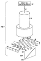
- Fig. 1 shows a plurality (here, six but the number is not part of the invention) of elongated scintillator strips 2, 4, 6, 8, 10 and 12 which are arranged to form a rectangular region.
- the strips are 1/4 inch wide by 1/2 inch thick by 3 inches long, but these dimensions are not part of the invention.
- the width of the strip determines the resolution of the detector module and the 1/4 inch figure was chosen because such a resolution is believed satisfactory for nuclear medicine application.
- the thickness of the strip determines the stopping power of the scintillators and 1/2 inch was chosen because this thickness will stop 90 - 95% of all incident 140 keV gamma radiation.
- Each scintillator strip has a first end (e.g. 2A, 4A, etc.) and a second end, (2B, 4B, etc.) and all the first ends (2A, 4A, etc.) of the strips are aligned to form a first side 16 of the region and all the second ends of the strips (2B, 4B, etc.) are aligned to form a second side 18 of the region.
- the region is normal to the direction of incidence of incoming gamma radiation.
- scintillator strips 2, 6 and 10 are made of NaI(Tl) and the other half (namely scintillator strips 4, 8 and 12) are made of CsI(Na). As shown, the scintillator strips are alternated so that adjacent scintillator strips are always made of different materials.
- the scintillator strips 2, 4 ... 12 form three pairs 20, 22 and 24, each pair 20, 22 and 24 containing a CsI(Na) strip and a NaI(Tl) strip.
- the pair 20 contains a NaI(Tl) scintillator strip 2 and a CsI(Na) scintillator strip 4.
- the first end of each of the strips in each pair are optically coupled together through a small light pipe, (e.g. 26) which is also coupled to an avalanche photodiode (e.g. 32 Fig. 2).
- the six strips are all optically coupled (as by a large light pipe, not shown) to a photomultiplier tube 38.
- the output 40 of the photomultiplier tube 38 is connected to a circuit 42 which is used to determine the decay time of scintillation events registered by the photomultiplier tube 38.
- the details of such circuits are known to persons skilled in the art and are therefore not described here. Some such details are contained in the EP-A-0 262 524.
- a temperature gradient is established along the lengths of the scintillator strips 2, 4 ... 12.
- the first side 16 is held at a temperature of approximately 0°C or below, and the second side 18 is held at a higher temperature.
- the temperature gradient is chosen to provide the resolution desired; the greater the gradient, the greater the resolution. 0°C was chosen because this reduces thermal noise output from the photodiodes described below.
- the decay time of a scintillation event detected by the photomultiplier tube 38 represents the location of the event along the X axis where, as here, a temperature gradient is established in the X direction.
- the Y position of the event is represented (to an accuracy equalling the width of a scintillator strip) by the particular strip (e.g. 2, or 4 etc.) in which the scintillation event has taken place. It would be possible to identify the strip (and therefore the Y coordinate) by mounting an avalanche photodiode to each individual one of the scintillator strips and registering, for each scintillation event, the identity of the correspondingly fired photodiode. However, this would be costly because avalanche photodiodes are highly expensive. Accordingly, in the preferred embodiment, the number of these photodiodes (e.g. 26, 28 and 30) is reduced.
- the decay time characteristics of e.g. Nal(Tl) are distinguishable from the decay time characteristics of CsI(Na).
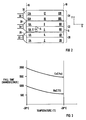
- One measure of decay time is the time required for a scintillation event to decay from 90% of its maximum amplitude to 10% of its maximum amplitude, and this is shown in Fig. 3 in an illustrative (not to scale) manner.
- the signal from the photomultiplier tube 38 is used to determine a) the identity of the scintillator material in which the scintillation event has taken place and b) the X coordinate of the scintillation event.
- a scintillation event E at the location shown in Fig.
- fall time as a measure of decay time is preferred because, in the temperature ranges which are currently under investigation, the fall time provides a basis upon which to distinguish between NaI(Tl) scintillations and CsI(Na) scintillations.
- the shapes of the decay time vs. temperature curves also differ between NaI(Tl) scintillations and CsI(Na) scintillations and these shape differences may also be used to accomplish the distinction.
- Persons skilled in the art can adapt the circuit 42 to measure whatever scintillation characteristics are used as the distinguishing features.
- scintillation materials are not necessary to the invention. If photodiodes drop in price, one material may be used and a photodiode may be mounted to each strip. Alternatively, more scintillator materials may be used, to increase the number of strips in each group and thereby further reduce the number of photodiodes.
- PIN photodiodes instead of avalanche photodiodes.
- the scintillator strips are long, there may be two photodiodes for each, one at each of the ends.
- the temperature along the first side 16 of the region is kept at 0°C or below to reduce the effect of thermal noise on the outputs from the photodiodes 26, 28 and 30.
- a heat sink made of a material with comparatively high thermal conductivity may advantageously be fixed along the first side 16 of the region and cooled to an appropriate temperature, while another heat sink which is appropriately heated/cooled may be fixed along the second side 18.
- the method by which the thermal gradient is established is not part of the invention.
- the module disclosed alone can be replicated in whatever configuration is required, since the problem of "edge packing" is minimized.
- a plurality of such modules can be disposed so that all the scintillator strips occupy a common plane, or so that the surfaces of the modules form a desired configuration, e.g., a surface which is a closed curve viewed on end and which surrounds a patient.
Landscapes
- Physics & Mathematics (AREA)
- Health & Medical Sciences (AREA)
- Spectroscopy & Molecular Physics (AREA)
- Molecular Biology (AREA)
- Life Sciences & Earth Sciences (AREA)
- General Physics & Mathematics (AREA)
- High Energy & Nuclear Physics (AREA)
- Engineering & Computer Science (AREA)
- Chemical & Material Sciences (AREA)
- Crystallography & Structural Chemistry (AREA)
- Biomedical Technology (AREA)
- General Health & Medical Sciences (AREA)
- Medical Informatics (AREA)
- Nuclear Medicine, Radiotherapy & Molecular Imaging (AREA)
- Optics & Photonics (AREA)
- Measurement Of Radiation (AREA)
- Nuclear Medicine (AREA)
Applications Claiming Priority (2)
| Application Number | Priority Date | Filing Date | Title |
|---|---|---|---|
| US174574 | 1988-03-29 | ||
| US07/174,574 US4879465A (en) | 1986-09-30 | 1988-03-29 | Detector module for scintillation cameras |
Publications (1)
| Publication Number | Publication Date |
|---|---|
| EP0337096A1 true EP0337096A1 (fr) | 1989-10-18 |
Family
ID=22636666
Family Applications (1)
| Application Number | Title | Priority Date | Filing Date |
|---|---|---|---|
| EP89103518A Ceased EP0337096A1 (fr) | 1988-03-29 | 1989-02-28 | Détecteur modulaire pour une caméra à scintillation |
Country Status (3)
| Country | Link |
|---|---|
| US (1) | US4879465A (fr) |
| EP (1) | EP0337096A1 (fr) |
| JP (1) | JPH01285887A (fr) |
Cited By (1)
| Publication number | Priority date | Publication date | Assignee | Title |
|---|---|---|---|---|
| WO2009058542A1 (fr) * | 2007-10-30 | 2009-05-07 | Rigaku Innovative Technologies, Inc. | Détecteur à scintillation avec fenêtre d'entrée pouvant être chauffée |
Families Citing this family (7)
| Publication number | Priority date | Publication date | Assignee | Title |
|---|---|---|---|---|
| JPH04213091A (ja) * | 1990-12-10 | 1992-08-04 | Konica Corp | 放射線量検出装置 |
| US5338937A (en) * | 1993-06-14 | 1994-08-16 | Sloan-Kettering Institute For Cancer Research | Radiation imaging device having an enlarged uniform field of view |
| US5753917A (en) * | 1995-06-06 | 1998-05-19 | Engdahl; John C. | Dual crystal scintillation camera |
| US6749761B1 (en) * | 2000-10-10 | 2004-06-15 | Cti Pet Systems, Inc. | Method for producing a high resolution detector array |
| US7157014B1 (en) | 2001-10-05 | 2007-01-02 | Cit Pet Systems, Inc. | Method for producing a high resolution detector array |
| WO2004111681A1 (fr) * | 2003-06-19 | 2004-12-23 | Ideas Asa | Detecteur de rayonnement modulaire dote de scintillateurs, de photodiodes a semiconducteur et d'un circuit de lecture integre, et leur procede d'assemblage |
| WO2019103997A1 (fr) * | 2017-11-24 | 2019-05-31 | Saint-Gobain Ceramics & Plastics, Inc. | Substrat comprenant des matériaux scintillateurs, système comprenant ledit substrat et procédé d'utilisation |
Citations (3)
| Publication number | Priority date | Publication date | Assignee | Title |
|---|---|---|---|---|
| FR2543691A1 (fr) * | 1983-03-31 | 1984-10-05 | Sendyk Andrzej | Detecteur pour la detection de position d'une radiation ionisante |
| EP0219648A1 (fr) * | 1985-10-18 | 1987-04-29 | Clayton Foundation for Research | Caméra pour tomographie à positrons avec plusieurs ensembles coplanaires de détecteurs |
| EP0262524A1 (fr) * | 1986-09-30 | 1988-04-06 | Siemens Aktiengesellschaft | Scintillateur chauffé |
Family Cites Families (2)
| Publication number | Priority date | Publication date | Assignee | Title |
|---|---|---|---|---|
| US4037105A (en) * | 1976-06-01 | 1977-07-19 | Laurer Gerard R | Radiation detector with array of different scintillators |
| US4672207A (en) * | 1985-08-21 | 1987-06-09 | The United States Of America As Represented By The United States Department Of Energy | Readout system for multi-crystal gamma cameras |
-
1988
- 1988-03-29 US US07/174,574 patent/US4879465A/en not_active Expired - Fee Related
-
1989
- 1989-02-28 EP EP89103518A patent/EP0337096A1/fr not_active Ceased
- 1989-03-28 JP JP1077963A patent/JPH01285887A/ja active Pending
Patent Citations (3)
| Publication number | Priority date | Publication date | Assignee | Title |
|---|---|---|---|---|
| FR2543691A1 (fr) * | 1983-03-31 | 1984-10-05 | Sendyk Andrzej | Detecteur pour la detection de position d'une radiation ionisante |
| EP0219648A1 (fr) * | 1985-10-18 | 1987-04-29 | Clayton Foundation for Research | Caméra pour tomographie à positrons avec plusieurs ensembles coplanaires de détecteurs |
| EP0262524A1 (fr) * | 1986-09-30 | 1988-04-06 | Siemens Aktiengesellschaft | Scintillateur chauffé |
Cited By (2)
| Publication number | Priority date | Publication date | Assignee | Title |
|---|---|---|---|---|
| WO2009058542A1 (fr) * | 2007-10-30 | 2009-05-07 | Rigaku Innovative Technologies, Inc. | Détecteur à scintillation avec fenêtre d'entrée pouvant être chauffée |
| US7684545B2 (en) | 2007-10-30 | 2010-03-23 | Rigaku Innovative Technologies, Inc. | X-ray window and resistive heater |
Also Published As
| Publication number | Publication date |
|---|---|
| US4879465A (en) | 1989-11-07 |
| JPH01285887A (ja) | 1989-11-16 |
Similar Documents
| Publication | Publication Date | Title |
|---|---|---|
| JP4313895B2 (ja) | 放射線検出装置 | |
| US7214943B2 (en) | Radiation or neutron detector using fiber optics | |
| US7166848B2 (en) | Three dimensional radiation detector | |
| JP4338177B2 (ja) | 3次元放射線位置検出器 | |
| CA1185019A (fr) | Groupes de detecteurs discrets de radiations ionisantes nombreux multiplexes au moyen de convertisseurs optiques fluorescents | |
| US7956331B2 (en) | Scintillation detector for positron emission tomography | |
| EP3210042B1 (fr) | Composant détecteur d'un détecteur de rayons x ou de rayons gamma | |
| US5122667A (en) | Means for measuring the depth interaction of gamma-rays in scintillation crystals in order to improve the spatial resolution of positron imaging systems | |
| US5506408A (en) | Gamma camera | |
| GB1564385A (en) | Arrangements for detecting ionising radiation | |
| JP2010527021A (ja) | 仮想pet検出器及びpet用の疑似画素化読み出し手法 | |
| JPS6295483A (ja) | 陽電子放射断層放射線カメラ | |
| CN115097511B (zh) | 基于mura编码方式的单位置灵敏探测器的双端成像伽玛相机 | |
| CN109581460B (zh) | 复合探测装置 | |
| CN112014873A (zh) | 双端读出探测器的作用深度定位分辨率快速确定方法 | |
| US4879465A (en) | Detector module for scintillation cameras | |
| US6124595A (en) | Gamma ray imaging detector with three dimensional event positioning and method of calculation | |
| WO1997006451A1 (fr) | Ensemble de detection a haute resolution pour imagerie a rayons gamma | |
| JP4358388B2 (ja) | ポジトロンイメージング装置 | |
| WO2018044606A1 (fr) | Systèmes et procédés permettant de commander un couplage optique entre des cristaux scintillateurs | |
| US4131798A (en) | Array gamma counter | |
| US6462341B1 (en) | Pixelated scintillation detector | |
| EP4095565A1 (fr) | Dispositif pour la détection de rayons gamma avec codification de profondeur d'interaction et temps de vol | |
| US3873838A (en) | Two-dimensional readout system for radiation detector | |
| EP0090594A1 (fr) | Caméra à scintillation |
Legal Events
| Date | Code | Title | Description |
|---|---|---|---|
| PUAI | Public reference made under article 153(3) epc to a published international application that has entered the european phase |
Free format text: ORIGINAL CODE: 0009012 |
|
| AK | Designated contracting states |
Kind code of ref document: A1 Designated state(s): DE FR GB NL |
|
| 17P | Request for examination filed |
Effective date: 19900328 |
|
| 17Q | First examination report despatched |
Effective date: 19910412 |
|
| STAA | Information on the status of an ep patent application or granted ep patent |
Free format text: STATUS: THE APPLICATION HAS BEEN REFUSED |
|
| 18R | Application refused |
Effective date: 19920313 |