EP0337491B1 - Méthode et dispositif pour la commande de l'instant d'allumage dans un moteur à combustion interne - Google Patents
Méthode et dispositif pour la commande de l'instant d'allumage dans un moteur à combustion interne Download PDFInfo
- Publication number
- EP0337491B1 EP0337491B1 EP89106751A EP89106751A EP0337491B1 EP 0337491 B1 EP0337491 B1 EP 0337491B1 EP 89106751 A EP89106751 A EP 89106751A EP 89106751 A EP89106751 A EP 89106751A EP 0337491 B1 EP0337491 B1 EP 0337491B1
- Authority
- EP
- European Patent Office
- Prior art keywords
- ignition timing
- correction
- engine
- engine speed
- change
- Prior art date
- Legal status (The legal status is an assumption and is not a legal conclusion. Google has not performed a legal analysis and makes no representation as to the accuracy of the status listed.)
- Expired - Lifetime
Links
- 238000000034 method Methods 0.000 title claims description 24
- 238000002485 combustion reaction Methods 0.000 title claims description 12
- 238000012937 correction Methods 0.000 claims description 39
- 230000008859 change Effects 0.000 claims description 33
- 230000007423 decrease Effects 0.000 claims description 6
- 230000001276 controlling effect Effects 0.000 description 10
- 239000000446 fuel Substances 0.000 description 9
- 230000003247 decreasing effect Effects 0.000 description 8
- 230000001788 irregular Effects 0.000 description 7
- 238000010586 diagram Methods 0.000 description 6
- 238000007796 conventional method Methods 0.000 description 5
- 230000000694 effects Effects 0.000 description 5
- 230000008569 process Effects 0.000 description 5
- 238000002347 injection Methods 0.000 description 3
- 239000007924 injection Substances 0.000 description 3
- 230000001133 acceleration Effects 0.000 description 2
- 230000006870 function Effects 0.000 description 2
- 239000003502 gasoline Substances 0.000 description 2
- 230000001629 suppression Effects 0.000 description 2
- 238000012360 testing method Methods 0.000 description 2
- 230000001419 dependent effect Effects 0.000 description 1
- 239000002828 fuel tank Substances 0.000 description 1
- 238000011835 investigation Methods 0.000 description 1
- 238000012986 modification Methods 0.000 description 1
- 230000004048 modification Effects 0.000 description 1
- 230000002265 prevention Effects 0.000 description 1
- 230000001105 regulatory effect Effects 0.000 description 1
- 230000004044 response Effects 0.000 description 1
- 230000000979 retarding effect Effects 0.000 description 1
Images



Classifications
-
- F—MECHANICAL ENGINEERING; LIGHTING; HEATING; WEAPONS; BLASTING
- F02—COMBUSTION ENGINES; HOT-GAS OR COMBUSTION-PRODUCT ENGINE PLANTS
- F02P—IGNITION, OTHER THAN COMPRESSION IGNITION, FOR INTERNAL-COMBUSTION ENGINES; TESTING OF IGNITION TIMING IN COMPRESSION-IGNITION ENGINES
- F02P5/00—Advancing or retarding ignition; Control therefor
- F02P5/04—Advancing or retarding ignition; Control therefor automatically, as a function of the working conditions of the engine or vehicle or of the atmospheric conditions
- F02P5/145—Advancing or retarding ignition; Control therefor automatically, as a function of the working conditions of the engine or vehicle or of the atmospheric conditions using electrical means
- F02P5/1455—Advancing or retarding ignition; Control therefor automatically, as a function of the working conditions of the engine or vehicle or of the atmospheric conditions using electrical means by using a second control of the closed loop type
-
- F—MECHANICAL ENGINEERING; LIGHTING; HEATING; WEAPONS; BLASTING
- F02—COMBUSTION ENGINES; HOT-GAS OR COMBUSTION-PRODUCT ENGINE PLANTS
- F02P—IGNITION, OTHER THAN COMPRESSION IGNITION, FOR INTERNAL-COMBUSTION ENGINES; TESTING OF IGNITION TIMING IN COMPRESSION-IGNITION ENGINES
- F02P5/00—Advancing or retarding ignition; Control therefor
- F02P5/04—Advancing or retarding ignition; Control therefor automatically, as a function of the working conditions of the engine or vehicle or of the atmospheric conditions
- F02P5/145—Advancing or retarding ignition; Control therefor automatically, as a function of the working conditions of the engine or vehicle or of the atmospheric conditions using electrical means
- F02P5/15—Digital data processing
- F02P5/1502—Digital data processing using one central computing unit
- F02P5/1504—Digital data processing using one central computing unit with particular means during a transient phase, e.g. acceleration, deceleration, gear change
-
- F—MECHANICAL ENGINEERING; LIGHTING; HEATING; WEAPONS; BLASTING
- F02—COMBUSTION ENGINES; HOT-GAS OR COMBUSTION-PRODUCT ENGINE PLANTS
- F02B—INTERNAL-COMBUSTION PISTON ENGINES; COMBUSTION ENGINES IN GENERAL
- F02B1/00—Engines characterised by fuel-air mixture compression
- F02B1/02—Engines characterised by fuel-air mixture compression with positive ignition
- F02B1/04—Engines characterised by fuel-air mixture compression with positive ignition with fuel-air mixture admission into cylinder
-
- Y—GENERAL TAGGING OF NEW TECHNOLOGICAL DEVELOPMENTS; GENERAL TAGGING OF CROSS-SECTIONAL TECHNOLOGIES SPANNING OVER SEVERAL SECTIONS OF THE IPC; TECHNICAL SUBJECTS COVERED BY FORMER USPC CROSS-REFERENCE ART COLLECTIONS [XRACs] AND DIGESTS
- Y02—TECHNOLOGIES OR APPLICATIONS FOR MITIGATION OR ADAPTATION AGAINST CLIMATE CHANGE
- Y02T—CLIMATE CHANGE MITIGATION TECHNOLOGIES RELATED TO TRANSPORTATION
- Y02T10/00—Road transport of goods or passengers
- Y02T10/10—Internal combustion engine [ICE] based vehicles
- Y02T10/40—Engine management systems
Definitions
- the present invention relates to a method and an apparatus for controlling the ignition timing in an internal combustion engine according to the preambles of the independent claims.
- a method and apparatus are known from EP-A-0 233 449.
- the invention may be used for engines of electric ignition type, such as gasoline engines and is suitable for preventing occurrence of irregular surge in acceleration operation.
- Prior art document EP-A-0 233 449 discloses an apparatus and a method for controlling the ignition timing in internal combustion engines.
- the ignition timing is controlled in that a change in engine speed is detected from a differentiated value dN/dt, and when dN/dt is larger than a predetermined value and when a value of dN/dt is positive, the ignition timing is retarded by a predetermined value from a fundamental ignition timing, and further, when the dN/dt is larger than a predetermined value and when the value of dN/dt is negative, the ignition timing is advanced by the predetermined value from the fundamental ignition timing.
- Prior art document EP-A- 0 109 535 discloses an apparatus for dampening the searching of an internal combustion engine within a vehicle.
- the ignition engine and the torque corresponding thereto is adjusted such that ignition is retarded when the engine speed increases and ignition is advanced, when the engine speed decreases.
- An object of the present invention is to provide an apparatus and a method for controlling ignition timing of internal combustion engines, which is applied to a vehicle of having an asymmetrical characteristic in terms of the change in the number of revolutions of the engine so as to constantly ensure satisfactory suppression of irregular awkward operation.
- the proposed method has the effect that the amount of correction of the ignition timing is changed in accordance with the sign of the detected change rate.
- FIG. 2 illustrates an example of an engine system to which the invention is applied.
- air to be sucked into an engine is introduced from an inlet portion 2 of an air cleaner 1 and passes through a hot-wire air flow sensor 3 for detecting the quantity of suction air, a duct 4, and a throttle body 5 having a throttle valve for controlling the air flow rate, and then enters into a collector 6.
- air is distributed to intake pipes 8 communicated directly with the internal combustion engine 7 so as to be sucked into cylinders thereof.
- fuel is fed from a fuel tank 9 and pressurized by means of a fuel pump 10 and then supplied to a fuel system which includes a fuel damper 11, a fuel filter 12, injection valves 13 and a fuel pressure regulator 14.
- the fuel thus supplied to the fuel system is regulated to be at a constant pressure by means of the regulator 14 and then injected into the intake pipes 8 through the injection valves (injectors) 13 provided on the intake pipes.
- the air flow sensor 3 is adapted to output a signal representing the quantity of suction air. This output signal is inputted in a control unit 15.
- the throttle body 5 is equipped with a throttle sensor 18 for detecting the degree of opening of the throttle valve. A signal from this sensor is also inputted in the control unit 15.
- a reference numeral 16 denotes a distributor which incorporates a crank angle sensor so as to produce a standard signal for the injection timing and ignition timing and a signal representing the number of revolutions, these signals being inputted into the control unit 15.
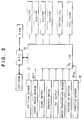
- FIG. 3 shows the details of the control unit 15.
- the control unit 15 is constituted by an arithmetic unit including an MPU (microprocessing unit), a ROM (read-only memory), an A/D (analog-digital) converter, and an input/output circuit.
- MPU microprocessing unit
- ROM read-only memory
- A/D analog-digital converter
- an input/output circuit In this control unit, a predetermined arithmetic operation is performed on the basis of the output signal from the air flow sensor 3, those from the distributor 16, etc. so as to produce an output signal indicative of the result of this operation.
- This output signal serves to actuate the injectors 13 so as to allow a required quantity of fuel to be injected into the respective intake pipes 8.
- control of the ignition timing is effected by sending another signal from the control unit to a power transistor of an ignition coil 17.
- FIGS 4a to 4c are flow charts showing the process for controlling the ignition timing according to the embodiment of the invention.
- the controlling process shown in Figures 4 is executed by the microcomputer including the MPU, the ROM and other like means in the control unit 15.
- the controlling process comprises three kinds of tasks, that is, a [BGJ] task serving as background job, a [10mS] task which is executed periodically every ten milliseconds, and an [REF interrupt] task which is executed each time an REF signal is produced.
- a [BGJ] task serving as background job
- a [10mS] task which is executed periodically every ten milliseconds
- an [REF interrupt] task which is executed each time an REF signal is produced.
- the [BGJ] task is a background job in which retrieval of an ignition timing map ADVMAP is carried out on the basis of the number N of revolutions of the engine and the degree ⁇ TH of opening of the throttle, and then read of a standard ignition timing TADVM is carried out, as shown in Figure 4a.
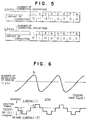
- Figure 6 shows the characteristic of the ignition timing ADV provided by the described embodiment at the time when the surging is occurred.
- the change in the number of revolutions of the engine is such that the number of revolutions is increased gradually while it is decreased relatively steeply.
- the correction for the standard ignition timing TADVM taken as a MAP value makes use of the tables shown in Figure 5
- retarding corrections are made at three ignition timing points, after the number of revolutions being to increase, during the period of increase which continues for a relatively long time.
- an advancing correction is made at one ignition timing point during the period of decrease which is finished in a short time.
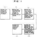
- the manner of correction described above can be expressed as shown in Figure 1 by way of a functional block diagram representing the controlling function of the ignition time unit (151,152,153,154,155).
- Figures 7 and 8 show what difference exists between the characteristics of the conventional method and the embodiment of the invention after the surging has been made to occur intentionally by suddenly stepping on the accelerator pedal for a short time (an accelerating operation effected by once stepping instantaneously).
- Figure 7 shows the results of a test conducted by making use of the conventional method
- Figure 8 shows the results of a test conducted in accordance with the present invention.
- the amount of correction and the number of correcting operations there are two methods of setting the amount of correction and the number of correcting operations shown in Figure 5. Namely, in the first method, upon confirming the pattern of the change in the number of revolutions of the engine, values which are capable of minimizing the magnitude of the change in the number of revolutions are set beforehand. In the second method, upon calculating the time periods during which the number of revolutions of the engine is being changed to increase and decrease, the magnitude of the change is checked at regular time intervals in relation to the thus calculated time periods so that, when it is judged that the magnitude of the change in the number of revolutions does not become small, the amount of correction and the number of correcting operations automatically undergo a feedback control to alter the set values.
- the correction for the ignition timing is made by increasing or decreasing both the amount of correction per one correcting operation and the number of correcting operations.
- modification can be made such that the correction is made by changing either of the above factors alone.
- the amounts of correction for the ignition timing which correction is made for the control of torque, can be given as independent optimum values in correspondence with the cases that the number of revolutions of the engine is being changed to increase and decrease, respectively. Therefore, it becomes possible to make adequate correction for the ignition timing in agreement with the pattern of the change in the number of revolutions of an engine, irrespectively of difference in types of the vehicles, such as automobiles, to which the present invention is applied. Consequently, it is possible to prevent any irregular awkward operation surely and easily at all times without distinction of the type of the vehicles.
Landscapes
- Engineering & Computer Science (AREA)
- Chemical & Material Sciences (AREA)
- Combustion & Propulsion (AREA)
- Mechanical Engineering (AREA)
- General Engineering & Computer Science (AREA)
- Theoretical Computer Science (AREA)
- Signal Processing (AREA)
- Electrical Control Of Ignition Timing (AREA)
Claims (7)
- Procédé pour commander la séquence d'allumage dans un moteur à combustion interne, comprenant les étapes consistant à :- déterminer une séquence d'allumage standard en fonction de paramètres du moteur,- déterminer le signe du taux de variation de la vitesse du moteur,- corriger la séquence d'allumage standard en fonction de valeurs de correction extraites d'une table de manière à obtenir une séquence d'allumage corrigée, et- délivrer la séquence d'allumage corrigée,caractérisé en ce que l'étape de correction de la séquence d'allumage standard comprend les étapes consistant à- corriger la séquence d'allumage standard pour un premier nombre prédéterminé d'allumages par addition de premières valeurs de correction extraites d'une première table, lorsque la vitesse du moteur diminue, ou- corriger la séquence d'allumage standard pour un second nombre prédéterminé d'allumages par addition de secondes valeurs de correction extraites d'une seconde table, différente de ladite première table, lorsque la vitesse du moteur augmente.
- Procédé selon la revendication 1, caractérisé en ce que la valeur absolue des valeurs mémorisées dans la seconde table est supérieure à celle des valeurs mémorisées dans la première table.
- Procédé selon la revendication 1, caractérisé en ce qu'il comprend en outre
l'étape consistant à commander la fréquence de correction de la séquence d'allumage exécutée pendant un intervalle de temps, pendant lequel la vitesse du moteur et/ou la quantité de variation de la séquence d'allumage pour chaque opération de correction varient. - Procédé selon l'une quelconque des revendications 1 à 3, caractérisé en ce que
lesdites quantités de correction de la séquence d'allumage standard sont calculées à partir d'une commande par réaction en fonction du taux de variation détecté de la vitesse du moteur. - Dispositif pour commander la séquence d'allumage dans un moteur à combustion interne, le dispositif étant particulièrement adapté pour la mise en oeuvre du procédé selon l'une des revendications 1 à 3, comprenant- des capteurs (3,18) pour détecter des paramètres de fonctionnement du moteur,- une unité de commande (15,151,152,153,154,155) apte à déterminer le signe du taux de variation de la vitesse du moteur, pour déterminer une séquence d'allumage standard en fonction des paramètres du moteur et corriger la séquence d'allumage standard en fonction de valeurs de correction extraites d'une table,caractérisé en ce que l'unité de commande (15,151,152,153, 154,155) comprend- une première table pour mémoriser des premières valeurs de correction pour la séquence d'allumage standard pour un premier nombre prédéterminé d'allumages, les valeurs de correction étant utilisées lorsque la vitesse du moteur diminue, et- une seconde table, qui diffère de ladite première table et sert à mémoriser des secondes valeurs de correction pour la séquence d'allumage standard pour un second nombre prédéterminé d'allumages, ces valeurs étant utilisées lorsque la vitesse du moteur augmente.
- Dispositif selon la revendication 5, caractérisé en ce qu'il comporte en outre des moyens (153,154) pour commander la fréquence de correction de la séquence d'allumage exécutée pendant un intervalle de temps, pendant lequel la vitesse du moteur et/ou la quantité de variation de la séquence d'allumage lors de chaque opération de correction varient.
- Dispositif selon la revendication 5 ou 6, caractérisé en ce qu'il comporte en outre une commande par réaction de la quantité de correction de la séquence d'allumage, la commande par réaction fonctionnant en fonction du taux de variation de la vitesse du moteur.
Applications Claiming Priority (2)
| Application Number | Priority Date | Filing Date | Title |
|---|---|---|---|
| JP63091807A JPH086667B2 (ja) | 1988-04-15 | 1988-04-15 | 内燃機関の点火時期制御装置 |
| JP91807/88 | 1988-04-15 |
Publications (2)
| Publication Number | Publication Date |
|---|---|
| EP0337491A1 EP0337491A1 (fr) | 1989-10-18 |
| EP0337491B1 true EP0337491B1 (fr) | 1996-07-03 |
Family
ID=14036898
Family Applications (1)
| Application Number | Title | Priority Date | Filing Date |
|---|---|---|---|
| EP89106751A Expired - Lifetime EP0337491B1 (fr) | 1988-04-15 | 1989-04-14 | Méthode et dispositif pour la commande de l'instant d'allumage dans un moteur à combustion interne |
Country Status (5)
| Country | Link |
|---|---|
| US (1) | US4953532A (fr) |
| EP (1) | EP0337491B1 (fr) |
| JP (1) | JPH086667B2 (fr) |
| KR (1) | KR970011035B1 (fr) |
| DE (1) | DE68926756T2 (fr) |
Cited By (1)
| Publication number | Priority date | Publication date | Assignee | Title |
|---|---|---|---|---|
| DE102004007919B4 (de) * | 2003-02-26 | 2011-09-15 | Ford Global Technologies, Llc (N.D.Ges.D. Staates Delaware) | Zündzeitpunktsteuerung auf Basis synchronisierter Zylinderereignisse |
Families Citing this family (10)
| Publication number | Priority date | Publication date | Assignee | Title |
|---|---|---|---|---|
| JP2731929B2 (ja) * | 1989-01-20 | 1998-03-25 | 富士重工業株式会社 | 点火時期制御装置 |
| US5050554A (en) * | 1989-04-26 | 1991-09-24 | Nippondenso Co., Ltd. | Ignition timing control apparatus for engines |
| JP3085382B2 (ja) * | 1989-08-25 | 2000-09-04 | 株式会社日立製作所 | 内燃機関の燃焼状態制御方法 |
| DE69129245T2 (de) * | 1990-02-14 | 1998-08-06 | Lucas Ind Plc | Vorrichtung zur Detektierung von Fehlzündungen |
| DE4011386A1 (de) * | 1990-04-07 | 1991-10-10 | Bosch Gmbh Robert | Verfahren zur zuendwinkelverstellung bei lastaenderungen |
| DE4021440A1 (de) * | 1990-07-05 | 1992-01-09 | Bosch Gmbh Robert | Einrichtung zum verhindern des ruckelns bei kraftfahrzeugen |
| JP2833935B2 (ja) * | 1992-07-10 | 1998-12-09 | 三菱電機株式会社 | 内燃機関制御装置 |
| CN104948375B (zh) * | 2015-05-05 | 2017-01-04 | 华南农业大学 | 基于闭环控制的cng发动机点火提前器及控制方法 |
| CN105736210B (zh) * | 2016-02-05 | 2018-10-16 | 潍柴动力股份有限公司 | 一种天然气发动机的瞬态调速率控制方法及装置 |
| JP7598774B2 (ja) * | 2021-01-28 | 2024-12-12 | 株式会社やまびこ | エンジン作業機 |
Family Cites Families (16)
| Publication number | Priority date | Publication date | Assignee | Title |
|---|---|---|---|---|
| DE2951755A1 (de) * | 1979-12-21 | 1981-07-02 | Alfred Teves Gmbh, 6000 Frankfurt | Verfahren und schaltungsanordnung zur umwandlung von in fahrzeugen vorliegenden und als frequenz dargestellten veraenderlichen physikalischen groessen in zur frequenz proportionale zahlenwerte bzw. signale |
| FR2477633B1 (fr) * | 1980-03-05 | 1987-05-22 | Bosch Gmbh Robert | Dispositif pour la regulation des processus d'allumage etou d'injection de carburant dans des moteurs a combustion interne |
| JPS5770953A (en) * | 1980-10-22 | 1982-05-01 | Nippon Denso Co Ltd | Ignition timing control method |
| JPS58172466A (ja) * | 1982-04-02 | 1983-10-11 | Nippon Denso Co Ltd | 多気筒内燃機関の点火時期制御方法 |
| GB2135391B (en) * | 1982-07-27 | 1986-08-28 | Marchal Equip Auto | Method for self-adaptive regulation of the ignition advance angle of a thermal engine with controlled ignition |
| FR2531145B1 (fr) * | 1982-07-27 | 1987-04-30 | Marchal Equip Auto | Procede de regulation auto-adaptative de l'angle d'avance a l'allumage d'un moteur thermique a allumage commande |
| DE3243235A1 (de) * | 1982-11-23 | 1984-05-24 | Robert Bosch Gmbh, 7000 Stuttgart | Einrichtung zum daempfen von ruckelschwingungen bei einer brennkraftmaschine in einem kraftfahrzeug |
| US4575800A (en) * | 1983-04-08 | 1986-03-11 | Optimizer Control Corporation | System for optimizing the timing of diesel or spark ignition engines |
| DE3313036C2 (de) * | 1983-04-12 | 1997-02-13 | Bosch Gmbh Robert | Vorrichtung zur Verhinderung des klopfenden Betriebs bei Brennkraftmaschinen |
| JPS606071A (ja) * | 1983-06-24 | 1985-01-12 | Toyota Motor Corp | 車両用エンジンの点火時期制御装置 |
| US4819171A (en) * | 1985-08-05 | 1989-04-04 | Nissan Motor Co., Limited | Engine spark timing control system |
| JP2511862B2 (ja) * | 1986-01-08 | 1996-07-03 | 株式会社日立製作所 | 内燃機関の点火時期制御方法 |
| JPH081165B2 (ja) * | 1986-05-23 | 1996-01-10 | 株式会社日立製作所 | 内燃機関の点火時期制御方法及び装置 |
| JPH076476B2 (ja) * | 1986-05-23 | 1995-01-30 | 株式会社日立製作所 | 内燃機関の点火時期制御装置 |
| DE3643943A1 (de) * | 1986-12-22 | 1988-06-30 | Ford Werke Ag | Verfahren zum vermeiden von getrieberasselgeraeuschen bei wechselgetrieben, insbesondere von kraftfahrzeugen |
| JPH076478B2 (ja) * | 1987-02-21 | 1995-01-30 | 株式会社ユニシアジェックス | 内燃機関の点火時期制御装置 |
-
1988
- 1988-04-15 JP JP63091807A patent/JPH086667B2/ja not_active Expired - Lifetime
-
1989
- 1989-04-12 KR KR1019890004806A patent/KR970011035B1/ko not_active Expired - Fee Related
- 1989-04-13 US US07/336,783 patent/US4953532A/en not_active Expired - Lifetime
- 1989-04-14 DE DE68926756T patent/DE68926756T2/de not_active Expired - Fee Related
- 1989-04-14 EP EP89106751A patent/EP0337491B1/fr not_active Expired - Lifetime
Cited By (1)
| Publication number | Priority date | Publication date | Assignee | Title |
|---|---|---|---|---|
| DE102004007919B4 (de) * | 2003-02-26 | 2011-09-15 | Ford Global Technologies, Llc (N.D.Ges.D. Staates Delaware) | Zündzeitpunktsteuerung auf Basis synchronisierter Zylinderereignisse |
Also Published As
| Publication number | Publication date |
|---|---|
| EP0337491A1 (fr) | 1989-10-18 |
| DE68926756D1 (de) | 1996-08-08 |
| DE68926756T2 (de) | 1996-11-28 |
| KR970011035B1 (ko) | 1997-07-05 |
| US4953532A (en) | 1990-09-04 |
| JPH086667B2 (ja) | 1996-01-29 |
| KR890016281A (ko) | 1989-11-28 |
| JPH01267361A (ja) | 1989-10-25 |
Similar Documents
| Publication | Publication Date | Title |
|---|---|---|
| US4799469A (en) | Apparatus and method for controlling ignition timing for internal combustion engine | |
| US4852537A (en) | Ignition timing control apparatus for internal combustion engine | |
| EP0924421B1 (fr) | Dispositif pour régler l'injection de carburant pour moteur à combustion interne | |
| US4953532A (en) | Ignition timing control unit for internal combustion engine | |
| US5058550A (en) | Method for determining the control values of a multicylinder internal combustion engine and apparatus therefor | |
| EP0385458B1 (fr) | Système anti-patinage pour véhicule équipé de moteur à combustion interne | |
| EP0690225B1 (fr) | Méthode et dispositif de commande de calage de l'allumage pour un moteur à combustion interne | |
| US5331934A (en) | Spark timing control system for a vehicle-driving internal combustion engine | |
| JPH06146942A (ja) | 内燃機関の失火検出装置 | |
| KR930002380B1 (ko) | 내연기관의 점화시기 제어장치 및 제어방법 | |
| US4836169A (en) | Engine control apparatus | |
| EP0500107B1 (fr) | Système de commande de l'instant d'allumage pour un moteur à combustion interne actionnant un véhicule | |
| JP2002364406A (ja) | 内燃機関の自動停止装置 | |
| JP3220844B2 (ja) | 車両用ディーゼル機関の燃料噴射時期制御装置 | |
| JPH0783104A (ja) | 点火時期制御方法 | |
| JPH0264263A (ja) | 内燃機関の点火時期制御装置 | |
| JPH01125567A (ja) | エンジン制御装置 | |
| JPH0531653B2 (fr) | ||
| JPS63246440A (ja) | エンジンの制御装置 | |
| JPH05321708A (ja) | 車両走行制御装置 | |
| KR19980078355A (ko) | 차량 주행 속도에 따른 점화에너지 보상방법 | |
| JPH025744A (ja) | エンジンの使用燃料判別装置 | |
| JPH02119651A (ja) | 過渡時の空燃比制御方法 | |
| JPS63113150A (ja) | 自動車用エンジンの振動低減装置 | |
| JPS63268976A (ja) | エンジンのノツク検出装置 |
Legal Events
| Date | Code | Title | Description |
|---|---|---|---|
| PUAI | Public reference made under article 153(3) epc to a published international application that has entered the european phase |
Free format text: ORIGINAL CODE: 0009012 |
|
| 17P | Request for examination filed |
Effective date: 19890801 |
|
| AK | Designated contracting states |
Kind code of ref document: A1 Designated state(s): DE FR GB |
|
| 17Q | First examination report despatched |
Effective date: 19920421 |
|
| GRAH | Despatch of communication of intention to grant a patent |
Free format text: ORIGINAL CODE: EPIDOS IGRA |
|
| GRAA | (expected) grant |
Free format text: ORIGINAL CODE: 0009210 |
|
| AK | Designated contracting states |
Kind code of ref document: B1 Designated state(s): DE FR GB |
|
| REF | Corresponds to: |
Ref document number: 68926756 Country of ref document: DE Date of ref document: 19960808 |
|
| ET | Fr: translation filed | ||
| PLBE | No opposition filed within time limit |
Free format text: ORIGINAL CODE: 0009261 |
|
| STAA | Information on the status of an ep patent application or granted ep patent |
Free format text: STATUS: NO OPPOSITION FILED WITHIN TIME LIMIT |
|
| 26N | No opposition filed | ||
| REG | Reference to a national code |
Ref country code: GB Ref legal event code: IF02 |
|
| PGFP | Annual fee paid to national office [announced via postgrant information from national office to epo] |
Ref country code: GB Payment date: 20030326 Year of fee payment: 15 |
|
| PG25 | Lapsed in a contracting state [announced via postgrant information from national office to epo] |
Ref country code: GB Free format text: LAPSE BECAUSE OF NON-PAYMENT OF DUE FEES Effective date: 20040414 |
|
| GBPC | Gb: european patent ceased through non-payment of renewal fee |
Effective date: 20040414 |
|
| PGFP | Annual fee paid to national office [announced via postgrant information from national office to epo] |
Ref country code: DE Payment date: 20050609 Year of fee payment: 17 |
|
| PG25 | Lapsed in a contracting state [announced via postgrant information from national office to epo] |
Ref country code: DE Free format text: LAPSE BECAUSE OF NON-PAYMENT OF DUE FEES Effective date: 20061101 |
|
| PGFP | Annual fee paid to national office [announced via postgrant information from national office to epo] |
Ref country code: FR Payment date: 20080319 Year of fee payment: 20 |