EP0337566A2 - Appareil à cassette à bande magnétique avec une plaque de têtes et son unité de têtes magnétiques - Google Patents
Appareil à cassette à bande magnétique avec une plaque de têtes et son unité de têtes magnétiques Download PDFInfo
- Publication number
- EP0337566A2 EP0337566A2 EP89200888A EP89200888A EP0337566A2 EP 0337566 A2 EP0337566 A2 EP 0337566A2 EP 89200888 A EP89200888 A EP 89200888A EP 89200888 A EP89200888 A EP 89200888A EP 0337566 A2 EP0337566 A2 EP 0337566A2
- Authority
- EP
- European Patent Office
- Prior art keywords
- tape
- head
- magnetic
- magnetic tape
- guide
- Prior art date
- Legal status (The legal status is an assumption and is not a legal conclusion. Google has not performed a legal analysis and makes no representation as to the accuracy of the status listed.)
- Withdrawn
Links
- 230000007704 transition Effects 0.000 claims abstract description 5
- 230000004323 axial length Effects 0.000 claims abstract description 3
- PZBPKYOVPCNPJY-UHFFFAOYSA-N 1-[2-(allyloxy)-2-(2,4-dichlorophenyl)ethyl]imidazole Chemical compound ClC1=CC(Cl)=CC=C1C(OCC=C)CN1C=NC=C1 PZBPKYOVPCNPJY-UHFFFAOYSA-N 0.000 description 1
- 230000004886 head movement Effects 0.000 description 1
- 230000001771 impaired effect Effects 0.000 description 1
- 238000002347 injection Methods 0.000 description 1
- 239000007924 injection Substances 0.000 description 1
- 238000004519 manufacturing process Methods 0.000 description 1
Images

Classifications
-
- G—PHYSICS
- G11—INFORMATION STORAGE
- G11B—INFORMATION STORAGE BASED ON RELATIVE MOVEMENT BETWEEN RECORD CARRIER AND TRANSDUCER
- G11B5/00—Recording by magnetisation or demagnetisation of a record carrier; Reproducing by magnetic means; Record carriers therefor
- G11B5/48—Disposition or mounting of heads or head supports relative to record carriers ; arrangements of heads, e.g. for scanning the record carrier to increase the relative speed
-
- G—PHYSICS
- G11—INFORMATION STORAGE
- G11B—INFORMATION STORAGE BASED ON RELATIVE MOVEMENT BETWEEN RECORD CARRIER AND TRANSDUCER
- G11B15/00—Driving, starting or stopping record carriers of filamentary or web form; Driving both such record carriers and heads; Guiding such record carriers or containers therefor; Control thereof; Control of operating function
- G11B15/60—Guiding record carrier
- G11B15/602—Guiding record carrier for track selection, acquisition or following
-
- G—PHYSICS
- G11—INFORMATION STORAGE
- G11B—INFORMATION STORAGE BASED ON RELATIVE MOVEMENT BETWEEN RECORD CARRIER AND TRANSDUCER
- G11B5/00—Recording by magnetisation or demagnetisation of a record carrier; Reproducing by magnetic means; Record carriers therefor
- G11B5/10—Structure or manufacture of housings or shields for heads
Definitions
- the invention relates to a magnetic tape cassette device with a head plate and a magnetic head arranged on the head plate with a cylindrical tape contact surface and an air gap, the magnetic head belonging to a head unit, with a head holder which has a tape guide in the tape transport direction in front and behind the magnetic head with cylindrically curved ones Guide surfaces and these unilaterally delimiting alignment surfaces at one of their axial ends, an imaginary surface connecting the alignment surfaces being perpendicular to the plane through the air gap, with a control edge adjoining each of the guide surfaces at the other axial end, which due to its inclination to the guide surface holds the magnetic tape during tape transport with a tape edge against the respective alignment surface, and the axial length of the guide surface is less than or equal to the tape width, and a magnetic head unit for such a magnetic tape cassette device.
- Such a magnetic tape cassette device with a head unit and a holder belonging to the head unit is known from EP-PS 0 120 518 (PHN 10.602).
- the advantage of the head holder with this magnetic tape cassette device is that the magnetic tape is always in the correct azimuth position during its transport over the tape contact surface of the magnetic head. This is important when using pre-recorded tapes that have been pre-recorded on other devices.
- the azimuth position of the magnetic tape cassette device must correspond to the azimuth position of the recording device for good reproduction.
- the magnetic head can be manufactured together with the holder as a complete unit at the manufacturer. The device manufacturer then no longer requires azimuth settings.
- the tape runs in play mode from a tape guide surface immediately in front of the magnetic head over the tape contact surface of the magnetic head to the tape guide surface immediately behind the head.
- This band course is slightly curved and tightened. This makes the tape stiff so that the control edges can perform their control function by pushing the magnetic tape against the alignment surfaces in one direction.
- MSS Music Sensing System
- each control edge of the head holder merges at a distance from the guide surface into an alternate limiter surface, the distance between the opposite alignment surfaces and alternate limiter surfaces being so greater than the bandwidth that the magnetic tape is lifted off when it is lifted off the guide surfaces while the magnetic tape is still in contact with the tape contact surface of the head, the position of the magnetic tape is limited in the width direction thereof with play, and the said distance increases from the center of the respective escape limiter surface to its lateral edges.
- alternative limiter areas means that Function of the control margins is not impaired during normal recording or game operations.
- the escape limiter surfaces ensure that the magnetic tape can only move sideways in the width direction within certain small limits. In order to be sure that this limited guidance always works correctly, it is provided that the mutual distance between the alternative limiter surfaces and the alignment surfaces is always greater than the greatest bandwidth.
- the evasive surfaces like all other surfaces of the holder, are to be manufactured in one piece with the holder. Since the surfaces influencing the tape are in front of and behind the head in the tape running direction, the position and function of the pressure felt of the cassette is not disturbed by the holder.
- the escape limiter surfaces are cylindrically curved. Due to the cylindrical curvature, the band edges always have only point-like, practically never flat contact with the escape limiter surfaces. This is important if the height of the tape run changes in front of and behind the magnetic head unit. This can be caused by running errors within the cassette.
- a tangential surface to the avoidance limiter surface runs approximately perpendicular to the band contact surface.
- the escape limiter surface thus runs approximately parallel to the alignment surface and it is ensured that the magnetic tape, even if it is displaced transversely to the transport direction on the tape contact surface, is still roughly guided.
- diverging capture surfaces are provided on the free ends of the escape limiter surfaces relative to the alignment surfaces.
- Fig. 1 shows a magnetic tape cassette device with a housing 1, a drive motor 2 and a cassette holding device 3. Three buttons 4, 5, 6 are used to operate the various operating functions of the magnetic tape cassette device 1, which are guided within the device in a manner not shown.
- a magnetic tape cassette 7 is inserted into the cassette holder 3 and has a pressure felt 9 supported on a spring 8.
- the magnetic tape cassette device has a head plate 10 which can be moved back and forth in the direction of the magnetic tape cassette 7. There is still a cue position between a fully advanced play position and a fully retracted position. The game position is shown in the drawing. In Fig. 1 it can be seen that the pressure felt 9 presses a magnetic tape 11 against a tape contact surface 12 of a magnetic head 13.
- the magnetic tape 11 is guided and transported between the pressure roller and the sound wave.
- the magnetic head 13 is arranged on the head plate 10 by means of a holder 16.
- the holder 16 and the magnetic head 13 are factory-connected to form a unit.
- the bracket 16 has side parts 17 of the magnetic head, between which the magnetic tape 11 runs through.
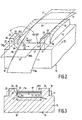
- One of the attachment parts 17 is shown greatly enlarged in FIGS. 2 and 3 together with the magnetic head and the magnetic tape.
- the attachment part 17 shown in FIGS. 2 and 3 represents only one half of the holder 16 and has a base body 18 from which projections 19, 20 project laterally.
- the base body 18 has a guide surface 21 which is cylindrically curved in the width direction according to arrow 22.
- the guide surface 21 is set back somewhat from the band contact surface 12 and its tangential plane. This ensures that the magnetic tape 11 between guide rollers, not shown, in the magnet tape cassette and the tape contact surface 12 has a curved course, both over the tape contact surface 12 and over the guide surface 21. This will tighten the band.
- the extension 19 has an alignment surface 23 adjacent to the guide surface 21.
- This alignment surface 23 is approximately perpendicular to the tangential surface to the guide surface 21.
- the alignment surface is arranged at one end of the guide surface 21, at the other end of the guide surface 21 there is a control edge 24 which, like the guide surface 21, is cylindrically curved.
- the tangential surface of the control edge includes an obtuse angle of 110 ° to 130 ° with the tangential surface of the guide surface 21. The angle is preferably approximately 120 °.
- the distance between the alignment surface 23 and the control edge 24 in the transition 21a to the guide surface 21 is smaller than the bandwidth. This means, as can be seen from FIG.
- Each control edge 24 of the lugs 20 merges at a distance from the guide surface 21 into an avoidance limiter surface 26 which has lateral edges 26a, 26b and between which the surface 26 preferably has a cylindrical curvature which in the center of the surface has the smallest distance to the opposite alignment surface 23.
- the distance c between the opposite alignment surface 23 and the avoidance limiter surface 26 is greater than the bandwidth b; the distance c remains the same from the transition point 27 to the open side. 2 and 3, the playing position of the tape is 11 and the cue position of the tape is 11 '. In the cue position 11 ', the magnetic tape is still in contact with the air gap 25 and the tape contact surface 12 in the area of the air gap, but it has been lifted from the guide surfaces 21.
- This cue position serves to reduce the friction of the tape when the tape is running fast, but to still take signals from the magnetic tape.
- the position of the magnetic tape 11 'in the cue position in the width direction 22 is limited with play between the alignment surface 23 and the evasive limiter surface 26th
- diverging capture surfaces 29 are provided in relation to the avoidance limiter surface 26, so that the magnate tape 11 can run into the holder 16 fastened to the head when the magnetic head 13 is advanced.
- An imaginary tangential surface to the avoidance limiter surface 26 runs approximately perpendicular to the band contact surface 12. This means that the alignment surface 23 and the avoidance limiter surface 26 in the direction of an arrow 30 according to FIG. H. the direction of head movement, locally have an approximately parallel course.
- the head holder with its individual parts is injection molded from plastic and is therefore easy and precise to close manufacture.
- the head holder can preferably be provided with a snap connection by means of which the head holder can be snapped onto the head plate with the head.
Landscapes
- Engineering & Computer Science (AREA)
- Manufacturing & Machinery (AREA)
- Adjustment Of The Magnetic Head Position Track Following On Tapes (AREA)
- Registering, Tensioning, Guiding Webs, And Rollers Therefor (AREA)
Priority Applications (1)
| Application Number | Priority Date | Filing Date | Title |
|---|---|---|---|
| DE8916097U DE8916097U1 (de) | 1988-04-14 | 1989-04-10 | Magnetbandkassettengerät mit einer Kopfplatte sowie eine Magnetkopfeinheit für dieses Magnetbandkassettengerät |
Applications Claiming Priority (2)
| Application Number | Priority Date | Filing Date | Title |
|---|---|---|---|
| DE3812362 | 1988-04-14 | ||
| DE3812362A DE3812362A1 (de) | 1988-04-14 | 1988-04-14 | Magnetbandkassettengeraet mit einer kopfplatte sowie eine magnetkopfeinheit fuer dieses magnetbandkassettengeraet |
Publications (2)
| Publication Number | Publication Date |
|---|---|
| EP0337566A2 true EP0337566A2 (fr) | 1989-10-18 |
| EP0337566A3 EP0337566A3 (fr) | 1990-09-26 |
Family
ID=6351934
Family Applications (1)
| Application Number | Title | Priority Date | Filing Date |
|---|---|---|---|
| EP19890200888 Withdrawn EP0337566A3 (fr) | 1988-04-14 | 1989-04-10 | Appareil à cassette à bande magnétique avec une plaque de têtes et son unité de têtes magnétiques |
Country Status (5)
| Country | Link |
|---|---|
| US (1) | US4962438A (fr) |
| EP (1) | EP0337566A3 (fr) |
| JP (1) | JPH01162143U (fr) |
| CN (1) | CN2051007U (fr) |
| DE (1) | DE3812362A1 (fr) |
Cited By (4)
| Publication number | Priority date | Publication date | Assignee | Title |
|---|---|---|---|---|
| EP0385359A3 (fr) * | 1989-02-28 | 1992-04-15 | Canon Denshi Kabushiki Kaisha | Tête magnétique |
| EP0549020A3 (en) * | 1991-12-11 | 1993-12-22 | Koninkl Philips Electronics Nv | Apparatus suitable for cooperation with a cassette provided with magnetic tape, magnetic-head unit and magnetic-head for use in the apparatus, housing suitable for use in the magnetic-head unit, and method of manufacturing the magnetic-head unit |
| EP0532012A3 (en) * | 1991-09-11 | 1994-08-10 | Matsushita Electric Industrial Co Ltd | Magnetic head assembly |
| EP0786764A1 (fr) * | 1996-01-26 | 1997-07-30 | Philips Patentverwaltung GmbH | Appareil à cassette à bande magnétique |
Families Citing this family (10)
| Publication number | Priority date | Publication date | Assignee | Title |
|---|---|---|---|---|
| US5134536A (en) * | 1988-08-18 | 1992-07-28 | Kabushiki Kaisha Sankyo Seiki Seisakusho | Tape guide for magnetic head |
| JPH04216354A (ja) * | 1990-02-16 | 1992-08-06 | Pioneer Electron Corp | 磁気ヘッド装置 |
| US5253135A (en) * | 1990-03-13 | 1993-10-12 | Canon Denshi Kabushiki Kaisha | Magnetic head having a tape sliding surface and projections formed on the tape sliding surface |
| CN1058349C (zh) * | 1992-06-10 | 2000-11-08 | 阿鲁普斯电气株式会社 | 磁头装置 |
| US5546259A (en) * | 1992-11-25 | 1996-08-13 | Matsushita Electric Industrial Co., Ltd. | Tape transporting apparatus including a tape guide with variable restricting force regions, each used depending upon the amount of tape tension |
| JP2587047Y2 (ja) * | 1993-05-26 | 1998-12-14 | アルプス電気株式会社 | 磁気ヘッド装置 |
| JPH0823979B2 (ja) * | 1993-08-23 | 1996-03-06 | インターナショナル・ビジネス・マシーンズ・コーポレイション | テープガイド |
| EP0729632A1 (fr) * | 1994-09-16 | 1996-09-04 | Koninklijke Philips Electronics N.V. | Systeme de memorisation et/ou de reproduction d'informations et cassette utilisee aux memes fins |
| DE19519371A1 (de) * | 1995-05-26 | 1996-11-28 | Philips Patentverwaltung | Magnetkopf mit einer Bandführungsvorrichtung |
| US20050133660A1 (en) * | 2003-12-23 | 2005-06-23 | Anderson James C. | Method and apparatus for guiding a moving tape |
Family Cites Families (8)
| Publication number | Priority date | Publication date | Assignee | Title |
|---|---|---|---|---|
| DE2460403B1 (de) * | 1974-12-20 | 1976-08-12 | Licentia Gmbh | Bandfuehrungseinrichtung |
| JPS5839556Y2 (ja) * | 1979-01-18 | 1983-09-06 | ナカミチ株式会社 | パッド衝合装置 |
| JPS5786178A (en) * | 1980-11-18 | 1982-05-29 | Sony Corp | Magnetic recording system |
| NL8200175A (nl) * | 1981-04-13 | 1982-11-01 | Philips Nv | Magneetbandcassetteapparaat alsmede megneetkopeenheid toepasbaar bij een dergelijk apparaat. |
| JPS5829168A (ja) * | 1981-08-13 | 1983-02-21 | Olympus Optical Co Ltd | 磁気記録テ−プ走行装置のテ−プガイド装置 |
| US4646186A (en) * | 1982-09-14 | 1987-02-24 | Alps Electric Co., Ltd. | Cassette tape recorder with plural tape guide structure |
| NL8300730A (nl) * | 1983-02-28 | 1984-09-17 | Philips Nv | Magneetbandcassetteapparaat alsmede magneetkopeenheid toepasbaar bij een dergelijk apparaat. |
| US4894737A (en) * | 1986-12-05 | 1990-01-16 | Canon Kabushiki Kaisha | Magnetic head apparatus having projections extending from at least a front side thereof |
-
1988
- 1988-04-14 DE DE3812362A patent/DE3812362A1/de not_active Ceased
-
1989
- 1989-04-10 EP EP19890200888 patent/EP0337566A3/fr not_active Withdrawn
- 1989-04-11 US US07/336,193 patent/US4962438A/en not_active Expired - Fee Related
- 1989-04-11 JP JP1989041724U patent/JPH01162143U/ja active Pending
- 1989-04-11 CN CN89204454U patent/CN2051007U/zh not_active Expired - Lifetime
Cited By (7)
| Publication number | Priority date | Publication date | Assignee | Title |
|---|---|---|---|---|
| EP0385359A3 (fr) * | 1989-02-28 | 1992-04-15 | Canon Denshi Kabushiki Kaisha | Tête magnétique |
| US5574606A (en) * | 1989-02-28 | 1996-11-12 | Canon Denshi Kabushiki Kaisha | Magnetic head having dust handling tape slide surface |
| EP0532012A3 (en) * | 1991-09-11 | 1994-08-10 | Matsushita Electric Industrial Co Ltd | Magnetic head assembly |
| US5638238A (en) * | 1991-09-11 | 1997-06-10 | Matsushita Electric Industrial Co., Ltd. | Magnetic head device with magnetic tape guides |
| EP0769779A3 (fr) * | 1991-09-11 | 1998-04-22 | Matsushita Electric Industrial Co., Ltd. | Assemblage de tête magnétique |
| EP0549020A3 (en) * | 1991-12-11 | 1993-12-22 | Koninkl Philips Electronics Nv | Apparatus suitable for cooperation with a cassette provided with magnetic tape, magnetic-head unit and magnetic-head for use in the apparatus, housing suitable for use in the magnetic-head unit, and method of manufacturing the magnetic-head unit |
| EP0786764A1 (fr) * | 1996-01-26 | 1997-07-30 | Philips Patentverwaltung GmbH | Appareil à cassette à bande magnétique |
Also Published As
| Publication number | Publication date |
|---|---|
| DE3812362A1 (de) | 1989-10-26 |
| JPH01162143U (fr) | 1989-11-10 |
| EP0337566A3 (fr) | 1990-09-26 |
| US4962438A (en) | 1990-10-09 |
| CN2051007U (zh) | 1990-01-10 |
Similar Documents
| Publication | Publication Date | Title |
|---|---|---|
| DE69113596T2 (de) | System mit einem Gerät und einer Kassette sowie Gerät und Kassette geeignet zum Gebrauch in einem derartigen System, und Magnetkopfeinheit geeignet zum Gebrauch in einem derartigen Gerät. | |
| DE3151715C2 (fr) | ||
| EP0337566A2 (fr) | Appareil à cassette à bande magnétique avec une plaque de têtes et son unité de têtes magnétiques | |
| DE2501866B2 (de) | Magnetbandkassette | |
| DE2946419A1 (de) | Kassettenrekorder | |
| DE2930072C2 (de) | Führungsvorrichtung für ein Magnetband in einer Magnetbandkassette | |
| DE2730381A1 (de) | Bandkassette | |
| DE1911748U (de) | Mehrspuriges magnettonbandgeraet. | |
| DE3003952A1 (de) | Vorrichtung zum aufnehmen und/oder wiedergeben von signalen auf einem magnetband | |
| DE2416298C3 (de) | Vorrichtung zum Führen eines bandförmigen Aufzeichnungsträgers | |
| AT394788B (de) | Kassette fuer einen aufzeichnungstraeger | |
| DE1574522B2 (de) | Loescheinrichtung fuer bandfoermige magnetische aufzeichnungstraeger mit einem permanentmagneten | |
| DE69012226T2 (de) | Magnetbandkassette. | |
| DE6937630U (de) | Magnetischer uebertrager | |
| DE2941437C2 (de) | Kassettenbandgerät mit automatischem Rücklauf | |
| DE69230247T2 (de) | Mit einer Kassette mit einem Magnetband zusammenarbeitendes Gerät sowie Magnetkopfeinheit und Magnetkopf zum Gebrauch in dem Gerät, Gehäuse zum Gebrauch in der Magnetkopfeinheit und Verfahren zum Herstellen der Magnetkopfeinheit | |
| DE2326869A1 (de) | Magnetisches aufzeichnungs- und wiedergabegeraet fuer spiralfoermige aufzeichnungsspuren | |
| EP0088472B1 (fr) | Cassette à bande magnétique | |
| DE3213621A1 (de) | Bandkassette und kassettenrecorder | |
| DE2538935C3 (de) | Justiereinrichtung für den Hör-Sprech-Kopf und den Löschkopf auf einer Kopfträgerplatte in einem Kassetten-Magnetbandgerät | |
| DE8916097U1 (de) | Magnetbandkassettengerät mit einer Kopfplatte sowie eine Magnetkopfeinheit für dieses Magnetbandkassettengerät | |
| DE2424621A1 (de) | Bandaufnahmegeraet | |
| DE2250027A1 (de) | Magnetbandabtasteinheit | |
| EP0051231B1 (fr) | Déclencheur électromagnétique | |
| DE2100591B2 (de) | Aufzeichnung^- und/oder Wiedergabegerät |
Legal Events
| Date | Code | Title | Description |
|---|---|---|---|
| PUAI | Public reference made under article 153(3) epc to a published international application that has entered the european phase |
Free format text: ORIGINAL CODE: 0009012 |
|
| AK | Designated contracting states |
Kind code of ref document: A2 Designated state(s): DE FR GB IT |
|
| PUAL | Search report despatched |
Free format text: ORIGINAL CODE: 0009013 |
|
| AK | Designated contracting states |
Kind code of ref document: A3 Designated state(s): DE FR GB IT |
|
| 17P | Request for examination filed |
Effective date: 19910321 |
|
| 17Q | First examination report despatched |
Effective date: 19920825 |
|
| STAA | Information on the status of an ep patent application or granted ep patent |
Free format text: STATUS: THE APPLICATION HAS BEEN WITHDRAWN |
|
| 18W | Application withdrawn |
Withdrawal date: 19930618 |