EP0337679A2 - Schalldämpfer für Gasströmungsapparate - Google Patents
Schalldämpfer für Gasströmungsapparate Download PDFInfo
- Publication number
- EP0337679A2 EP0337679A2 EP89303468A EP89303468A EP0337679A2 EP 0337679 A2 EP0337679 A2 EP 0337679A2 EP 89303468 A EP89303468 A EP 89303468A EP 89303468 A EP89303468 A EP 89303468A EP 0337679 A2 EP0337679 A2 EP 0337679A2
- Authority
- EP
- European Patent Office
- Prior art keywords
- silencer
- ducting
- pod
- length
- fan
- Prior art date
- Legal status (The legal status is an assumption and is not a legal conclusion. Google has not performed a legal analysis and makes no representation as to the accuracy of the status listed.)
- Withdrawn
Links
Images


Classifications
-
- F—MECHANICAL ENGINEERING; LIGHTING; HEATING; WEAPONS; BLASTING
- F24—HEATING; RANGES; VENTILATING
- F24F—AIR-CONDITIONING; AIR-HUMIDIFICATION; VENTILATION; USE OF AIR CURRENTS FOR SCREENING
- F24F13/00—Details common to, or for air-conditioning, air-humidification, ventilation or use of air currents for screening
- F24F13/24—Means for preventing or suppressing noise
Definitions
- the invention relates to silencers for gas flow apparatus, and in particular to silencers for the auxiliary fans used in the ventilation ducts in coal mines.
- the invention as claimed seeks to provide a particularly effective form of silencer of which the sound attenuating material can very easily be renewed.
- a silencer embodying the invention results in a very effective endways silencing and prevents the spread of sound along the axis of the ducting in which the silencer is installed.
- a further advantage is that the silencer does not affect the flow of air along the ducting or interfere with the routine inspection of a fan within the ducting by a maintenance worker.
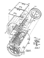
- the fan silencer there illustrated includes what is in effect a length of ducting generally indicated 10 for connection either on the inlet side or on the outlet side of an auxiliary fan in a coal mine for example, the opposite ends of the ducting being provided with respective flanges 12,12 for this purpose.
- a major length of the ducting 10 is surrounded by a generally cylindrical outer casing 14 to produce a generally annular space 16 surrounding the length of ducting, the space 16 being closed at its opposite ends by respective end walls 18,18.
- a major length 11 of the ducting within the outer casing is rotatably mounted relative to the outer casing on spigot portions of the ducting which pass through the end walls 18,18.
- Said major length of ducting is made of a heavy duty steel mesh material so that sound waves are able to travel radially outwards through its walls with a corresponding reduction in the sound waves passing along the ducting beyond the silencer.
- the outer casing is provided with a longitudinally extending access aperture 20 through which sound deadening material can be entered into the casing to be packed around the length of ducting within it.
- the access aperture 20 is provided with a closure panel 22 which can be fixed in position by means of quick release fastenings (not shown).
- the sound deadening material is shown to be provided in the form of an elongate blanket of material 21 which can be fed into the casing through the access aperture 20, the feeding of the material through the access aperture being facilitated by the rotation of the rotatable length of ducting.
- the sound deadening material need not necessarily be provided in this form.
- it could alternatively be provided in the form of a connected series of elongate silencer elements which can be fed through the access aperture for each element to extend longitudinally of the generally annular space within the outer casing.
- the side wall of the ducting within the outer casing is provided, as shown, with a removable cover plate 24 covering an opening through which, in use of the silencer, a maintenance worker can gain access to the interior of the ducting for the purpose of carrying out routine inspection of the adjacent fan, that is to say for example, for carrying out a visual inspection of the fan to check on the build-up of dust and dirt and to check on the condition of the fan bearings in normal manner.
- the closure panel 22 for the access aperture in the outer casing is provided with means whereby a de-gassing operation can be carried out, as is sometimes required in coal mines.
- these means are shown to take the form of a pair of slidable plates 26,26 which can be operated to allow a controlled flow of air into the ventilation ducting through respective inlet ports 28,28 in the closure panel.
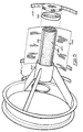
- FIGS 4 and 5 illustrate the construction of a so-called silencer pod generally indicated 30 in Figures 1 to 3.
- the pod is of generally cylindrical shape and is located at the axis of the ducting by three inclined arms 32 which are equally spaced within a carrier ring 34.
- the carrier ring is a flanged ring adapted to be located between one of the flanges 12 of the length of ducting 10 and a similar flange of a length of adjacent ducting so that the pod in this instance is located within the rotatably mounted length of ducting 11.
- the pod consists of two steel cylinders 34,36 joined together by two lengths of steel strip 38.
- a coiled length of sound absorbant material 40 is located between the lengths of steel strip and wire mesh material 42 wound around the assembly retains the sound absorbant material in position.
- the ends of the pod are capped with wire mesh material held in place with steel bands 44 riveted in position as shown in Figure 4.
- the sound absorbing material of which it is made and which may have become clogged with dust and dirt, to be removed and replaced by new material. This can be done by a maintenance worker gaining access to the interior of the ducting by removing the cover plate 24 as previously described.
- the fan silencer there illustrated is basically the same as that illustrated in Figures 1 to 3 but in this case it can be seen that the major length 11 of the ducting within the outer casing, made of heavy duty steel mesh material, has longitudinally extending stringers 110 and circumferentially extending ribs 112. Opposite end portions of the stringers slidably engage the radially outer surfaces of respective spigot portions 114 of the ducting which pass through the end walls 18.
- a series of apertured metal tabs 116 are welded to the free edges of the steel mesh material defining the opening through which a maintenance worker can gain access to the interior of the ducting. Similar apertured metal tabs 118 are welded to the edges of the cover plate 24 and screws 120 are provided for engaging the respective pairs of apertures to secure the cover plate in position.
- the access aperture 20 is provided with a pair of closure panels 22 arranged side by side.
- a pair of angle pieces 122,122 extend in back to back relation across the aperture 20 and are bolted between pairs of brackets 124,124 welded within the access aperture as shown.
- the arrangement is such that if the fastenings by means of which the closure panels are fixed in position are slackened off, said panels can be wedged partially open, either selectively or together (using any convenient items as wedges beneath the edges of the panels).
- the closure panels are in this case not provided with slidable plates to allow controlled flow of air into the ventilation ducting.
- the partial wedging open of the closure panels referred to is a convenient alternative method whereby a de-gassing operation can be carried out.
- a plurality of hooks 23 which can be engaged with the steel mesh material of the rotatable length of ducting to facilitate the feeding of the sound deadening material through the access aperture.
- hooks could of course also be provided in the case where the sound deadening material is provided in the form of a connected series of elongate silencer elements).
- the carrier ring 34 for the pod is again located between one of the flanges of the fan silencer and a similar flange (not shown) of a length of adjacent ducting.
- each fastening is constituted by a screwthreaded stud 124 which extends through a hole in a flange surrounding the access aperture 20 and is secured by a nut 126 on the underside of the flange.
- a toggle member 128 extends across a slot in the stud, and a pin 130 which extends diametrically of the stud passes through a slot 132 in the toggle member.
- each toggle member can be turned to the position shown in full lines in Figure 7 and can be struck with a hammer to bring about a wedging action.
- the scallop-like form of the lower surface of the slot in each toggle member causes the toggle member to remain in the wedging position to which it has been brought by the hammer blow.
- a fan silencer embodying the invention may be used otherwise than in the ventilation ducting of coal mines.
- a fan silencer embodying the invention may be used in connection with any noisy producer of a gas flow, for example a gas turbine (where there would be a requirement for periodic cleaning of the element) or a paraffin fired gas heater.
Landscapes
- Engineering & Computer Science (AREA)
- Chemical & Material Sciences (AREA)
- Combustion & Propulsion (AREA)
- Mechanical Engineering (AREA)
- General Engineering & Computer Science (AREA)
- Pipe Accessories (AREA)
- Structures Of Non-Positive Displacement Pumps (AREA)
Applications Claiming Priority (2)
| Application Number | Priority Date | Filing Date | Title |
|---|---|---|---|
| GB8808696 | 1988-04-13 | ||
| GB888808696A GB8808696D0 (en) | 1988-04-13 | 1988-04-13 | Silencer for gas flow apparatus |
Publications (2)
| Publication Number | Publication Date |
|---|---|
| EP0337679A2 true EP0337679A2 (de) | 1989-10-18 |
| EP0337679A3 EP0337679A3 (de) | 1991-08-28 |
Family
ID=10635110
Family Applications (1)
| Application Number | Title | Priority Date | Filing Date |
|---|---|---|---|
| EP19890303468 Withdrawn EP0337679A3 (de) | 1988-04-13 | 1989-04-07 | Schalldämpfer für Gasströmungsapparate |
Country Status (2)
| Country | Link |
|---|---|
| EP (1) | EP0337679A3 (de) |
| GB (1) | GB8808696D0 (de) |
Cited By (2)
| Publication number | Priority date | Publication date | Assignee | Title |
|---|---|---|---|---|
| US5260523A (en) * | 1990-11-20 | 1993-11-09 | Valmet Paper Machinery, Inc. | Absorptive sound attenuator, in particular for air ducts in paper mills |
| EP3073208A1 (de) * | 2015-03-26 | 2016-09-28 | MAICO Elektroapparate-Fabrik GmbH | Schalldämpfer für eine lüftungsanordnung, schalldämpferanordnung, lüftungseinrichtung sowie verfahren zum herstelllen eines schalldämpfers |
Families Citing this family (1)
| Publication number | Priority date | Publication date | Assignee | Title |
|---|---|---|---|---|
| CN110940083B (zh) * | 2019-12-31 | 2023-10-24 | 天津丽茂源松节能技术有限公司 | 一种新风系统的消音装置 |
Family Cites Families (6)
| Publication number | Priority date | Publication date | Assignee | Title |
|---|---|---|---|---|
| US3112007A (en) * | 1961-11-01 | 1963-11-26 | Arvin Ind Inc | Silencing element for exhaust gas conduit |
| FR1596223A (de) * | 1968-05-17 | 1970-06-15 | ||
| DE2048676A1 (de) * | 1970-10-03 | 1972-04-06 | Kunze, Richard, 7500 Karlsruhe; Schneider, Peter, 7503 Neureut | Abgasschalldämpfer |
| US3949830A (en) * | 1975-06-20 | 1976-04-13 | George Koch Sons, Inc. | Fan silencer |
| FR2505416B1 (fr) * | 1981-05-11 | 1986-09-12 | Cogema | Installation de ventilation, notamment ventilateur industriel |
| GB8615909D0 (en) * | 1986-06-30 | 1986-08-06 | Tomac Mining Products Ltd | Fan silencers |
-
1988
- 1988-04-13 GB GB888808696A patent/GB8808696D0/en active Pending
-
1989
- 1989-04-07 EP EP19890303468 patent/EP0337679A3/de not_active Withdrawn
Cited By (2)
| Publication number | Priority date | Publication date | Assignee | Title |
|---|---|---|---|---|
| US5260523A (en) * | 1990-11-20 | 1993-11-09 | Valmet Paper Machinery, Inc. | Absorptive sound attenuator, in particular for air ducts in paper mills |
| EP3073208A1 (de) * | 2015-03-26 | 2016-09-28 | MAICO Elektroapparate-Fabrik GmbH | Schalldämpfer für eine lüftungsanordnung, schalldämpferanordnung, lüftungseinrichtung sowie verfahren zum herstelllen eines schalldämpfers |
Also Published As
| Publication number | Publication date |
|---|---|
| EP0337679A3 (de) | 1991-08-28 |
| GB8808696D0 (en) | 1988-05-18 |
Similar Documents
| Publication | Publication Date | Title |
|---|---|---|
| US5162620A (en) | Dual flow turbine engine muffler | |
| DE69103864T2 (de) | Schalldämpfer mit Katalysator. | |
| US5758497A (en) | Silencer | |
| US6193011B1 (en) | Fan inlet flow controller | |
| DE19514990B4 (de) | Filterschalldämpfer | |
| US3949830A (en) | Fan silencer | |
| EP0716272A2 (de) | Geräuschreduzierte Dunstabzugshaube | |
| DE3225347C2 (de) | Wassergekühlte Brennkraftmaschine | |
| WO2022069138A1 (de) | Scheibenbremsanordnung, bremssattelbaugruppe und bremssattelhalter | |
| DE2547523B2 (de) | Brennkraftmaschine mit geräuschdämpfender Verschalung | |
| DE102020114917A1 (de) | Abgasschalldämpfungsvorrichtung | |
| EP0337679A2 (de) | Schalldämpfer für Gasströmungsapparate | |
| US5196653A (en) | Muffler for air powered turbine drive | |
| US1909394A (en) | Muffler | |
| DE10022240A1 (de) | Filterschalldämpfer | |
| US5486088A (en) | Steam turbine steam strainer | |
| EP1913242B1 (de) | Schalldämpfer für gasturbinenanlagen | |
| GB2195706A (en) | Fan silencers | |
| DE2225028A1 (de) | Auspuffschalldämpfer und Funkenfänger | |
| DE2309571A1 (de) | Auspuff-schalldaempfer fuer zweitaktmotore | |
| US1015698A (en) | Gas-engine silencer. | |
| EP2334915A1 (de) | Abgasschalldämpfer mit offener kammer sowie entsprechende herstellungs- und verwendungsverfahren | |
| HUE026934T2 (en) | Noise canceling device for ventilation fans | |
| DE19920279C2 (de) | Drehkolbengebläseanlage | |
| US5288204A (en) | Gas turbine engine support structure |
Legal Events
| Date | Code | Title | Description |
|---|---|---|---|
| PUAI | Public reference made under article 153(3) epc to a published international application that has entered the european phase |
Free format text: ORIGINAL CODE: 0009012 |
|
| AK | Designated contracting states |
Kind code of ref document: A2 Designated state(s): BE DE ES FR GB |
|
| PUAL | Search report despatched |
Free format text: ORIGINAL CODE: 0009013 |
|
| AK | Designated contracting states |
Kind code of ref document: A3 Designated state(s): BE DE ES FR GB |
|
| STAA | Information on the status of an ep patent application or granted ep patent |
Free format text: STATUS: THE APPLICATION IS DEEMED TO BE WITHDRAWN |
|
| 18D | Application deemed to be withdrawn |
Effective date: 19920229 |