EP0337778B1 - Flüssigkeitsbehälter mit Dosiereinrichtung - Google Patents
Flüssigkeitsbehälter mit Dosiereinrichtung Download PDFInfo
- Publication number
- EP0337778B1 EP0337778B1 EP89303656A EP89303656A EP0337778B1 EP 0337778 B1 EP0337778 B1 EP 0337778B1 EP 89303656 A EP89303656 A EP 89303656A EP 89303656 A EP89303656 A EP 89303656A EP 0337778 B1 EP0337778 B1 EP 0337778B1
- Authority
- EP
- European Patent Office
- Prior art keywords
- plunger
- timer
- fluid
- wall
- flange
- Prior art date
- Legal status (The legal status is an assumption and is not a legal conclusion. Google has not performed a legal analysis and makes no representation as to the accuracy of the status listed.)
- Expired - Lifetime
Links
- 239000012530 fluid Substances 0.000 title claims description 80
- 238000007789 sealing Methods 0.000 claims description 14
- 238000004891 communication Methods 0.000 claims description 4
- 230000005484 gravity Effects 0.000 claims description 4
- 238000000034 method Methods 0.000 description 9
- 239000011324 bead Substances 0.000 description 6
- 230000000903 blocking effect Effects 0.000 description 5
- 239000007788 liquid Substances 0.000 description 3
- -1 polyethylene Polymers 0.000 description 3
- 239000004698 Polyethylene Substances 0.000 description 2
- TZCXTZWJZNENPQ-UHFFFAOYSA-L barium sulfate Chemical compound [Ba+2].[O-]S([O-])(=O)=O TZCXTZWJZNENPQ-UHFFFAOYSA-L 0.000 description 2
- 239000000463 material Substances 0.000 description 2
- 229920000573 polyethylene Polymers 0.000 description 2
- 238000013022 venting Methods 0.000 description 2
- 239000004743 Polypropylene Substances 0.000 description 1
- 229920001807 Urea-formaldehyde Polymers 0.000 description 1
- 230000000295 complement effect Effects 0.000 description 1
- 238000002347 injection Methods 0.000 description 1
- 239000007924 injection Substances 0.000 description 1
- 230000002452 interceptive effect Effects 0.000 description 1
- 238000004519 manufacturing process Methods 0.000 description 1
- 239000002991 molded plastic Substances 0.000 description 1
- ODGAOXROABLFNM-UHFFFAOYSA-N polynoxylin Chemical compound O=C.NC(N)=O ODGAOXROABLFNM-UHFFFAOYSA-N 0.000 description 1
- 229920001155 polypropylene Polymers 0.000 description 1
- 230000001105 regulatory effect Effects 0.000 description 1
- 230000000717 retained effect Effects 0.000 description 1
- 239000007787 solid Substances 0.000 description 1
- 239000000243 solution Substances 0.000 description 1
- 229920001187 thermosetting polymer Polymers 0.000 description 1
Images



Classifications
-
- G—PHYSICS
- G01—MEASURING; TESTING
- G01F—MEASURING VOLUME, VOLUME FLOW, MASS FLOW OR LIQUID LEVEL; METERING BY VOLUME
- G01F11/00—Apparatus requiring external operation adapted at each repeated and identical operation to measure and separate a predetermined volume of fluid or fluent solid material from a supply or container, without regard to weight, and to deliver it
- G01F11/10—Apparatus requiring external operation adapted at each repeated and identical operation to measure and separate a predetermined volume of fluid or fluent solid material from a supply or container, without regard to weight, and to deliver it with measuring chambers moved during operation
- G01F11/26—Apparatus requiring external operation adapted at each repeated and identical operation to measure and separate a predetermined volume of fluid or fluent solid material from a supply or container, without regard to weight, and to deliver it with measuring chambers moved during operation wherein the measuring chamber is filled and emptied by tilting or inverting the supply vessel, e.g. bottle-emptying apparatus
- G01F11/262—Apparatus requiring external operation adapted at each repeated and identical operation to measure and separate a predetermined volume of fluid or fluent solid material from a supply or container, without regard to weight, and to deliver it with measuring chambers moved during operation wherein the measuring chamber is filled and emptied by tilting or inverting the supply vessel, e.g. bottle-emptying apparatus for liquid or semi-liquid
- G01F11/263—Apparatus requiring external operation adapted at each repeated and identical operation to measure and separate a predetermined volume of fluid or fluent solid material from a supply or container, without regard to weight, and to deliver it with measuring chambers moved during operation wherein the measuring chamber is filled and emptied by tilting or inverting the supply vessel, e.g. bottle-emptying apparatus for liquid or semi-liquid with valves
-
- G—PHYSICS
- G01—MEASURING; TESTING
- G01F—MEASURING VOLUME, VOLUME FLOW, MASS FLOW OR LIQUID LEVEL; METERING BY VOLUME
- G01F11/00—Apparatus requiring external operation adapted at each repeated and identical operation to measure and separate a predetermined volume of fluid or fluent solid material from a supply or container, without regard to weight, and to deliver it
- G01F11/10—Apparatus requiring external operation adapted at each repeated and identical operation to measure and separate a predetermined volume of fluid or fluent solid material from a supply or container, without regard to weight, and to deliver it with measuring chambers moved during operation
- G01F11/26—Apparatus requiring external operation adapted at each repeated and identical operation to measure and separate a predetermined volume of fluid or fluent solid material from a supply or container, without regard to weight, and to deliver it with measuring chambers moved during operation wherein the measuring chamber is filled and emptied by tilting or inverting the supply vessel, e.g. bottle-emptying apparatus
- G01F11/268—Apparatus requiring external operation adapted at each repeated and identical operation to measure and separate a predetermined volume of fluid or fluent solid material from a supply or container, without regard to weight, and to deliver it with measuring chambers moved during operation wherein the measuring chamber is filled and emptied by tilting or inverting the supply vessel, e.g. bottle-emptying apparatus with provision for varying the volume to be delivered
-
- G—PHYSICS
- G01—MEASURING; TESTING
- G01F—MEASURING VOLUME, VOLUME FLOW, MASS FLOW OR LIQUID LEVEL; METERING BY VOLUME
- G01F13/00—Apparatus for measuring by volume and delivering fluids or fluent solid materials, not provided for in the preceding groups
- G01F13/006—Apparatus for measuring by volume and delivering fluids or fluent solid materials, not provided for in the preceding groups measuring volume in function of time
Definitions
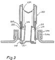
- a number of ribs 136 extend radially inwardly from the inner cylindrical skirt 133 of the cap 128. These ribs guide the tubular part 122 of the plunger 120 as it moves axially.
- the upper ends of the radial ribs 136 are provided with a central deflector plate 137 forming an annular outlet opening 132 together with the inner skirt 133.
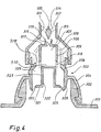
- the plunger 320 moves forward owing to the prevailing pressure and displaces fluid from the timer chamber 315, and after a relatively short travel the wall 310 and the cylindrical side walls of the plunger 320 slide past the openings 318 and close them off. At the same time, fluid flows through the circular chamber 326 and the passageway 319 directly out through the outlet opening 332 and this continues until the flange 321 of the plunger 320 eventually abuts the conical part 308, thus preventing further fluid flow through the dosage assembly. In the final position the end of the plunger 320 substantially abuts the lower wall 317 of the cup-shaped part 307 so that the timer chamber 315 is substantially empty.
- the invention can be varied in many ways without thus deviating from the scope of the invention.
- the cap can, for example, be non-adjustably connected with the stopper and optionally be an integral part thereof.
Landscapes
- Physics & Mathematics (AREA)
- Fluid Mechanics (AREA)
- General Physics & Mathematics (AREA)
- Closures For Containers (AREA)
- Containers And Packaging Bodies Having A Special Means To Remove Contents (AREA)
- Infusion, Injection, And Reservoir Apparatuses (AREA)
- Investigating Or Analysing Biological Materials (AREA)
- Medical Preparation Storing Or Oral Administration Devices (AREA)
Claims (15)
- Dosier-Meßanordnung (3, 103, 203, 303, 403) für einen Fluidbehälter, der einen Hals (2, 102, 202, 302, 402) mit einer Öffnung aufweist, durch die Fluid abgegeben wird, wenn der Behälter umgedreht wird, mit einem Verschlußelement (4, 104, 204, 304, 404), das auf dem Hals des Behälters montiert ist und das einen Auslaßbereich mit einer Auslaßöffnung (32, 132, 232, 332, 432) für das Ausströmen von Fluid aus dem Behälter hat, wobei eine Zeitgeberkammer (15, 115, 215, 315, 415), die mit einer ringförmigen Wand (10, 1106, 206, 309, 411) und einem Kolben (20, 120, 220, 320, 420) gebildet ist, unabhängig von dem Verschluß geformt ist, wobei der Kolben in bezug auf die ringförmige Wand der Zeitgeberkammer unter dem Einfluß der Schwerkraft aus einer Startposition in eine Endposition bewegbar ist, wenn der Behälter umgedreht wird, mit einer Einlaßöffnung (18, 118, 218, 318, 418) für die Zeitgeberkammer, die eine Fluidströmung zwischen der Zeitgeberkammer und dem Behälter zuläßt, so daß Fluid in die Zeitgeberkammer (15, 115, 215, 315, 415) eintreten kann, dadurch gekennzeichnet, daß der Kolben (20, 120, 220, 320, 420) einen Zeitgeberflansch oder -wand (21, 121, 221, 310, 421) aufweist, der eine Wand der Zeitgeberkammer bildet und sich radial in bezug auf die ringförmige Wand (10, 106, 206, 309, 411) der Zeitgeberkammer erstreckt und mit dieser in verschiebbarer, abgedichteter Beziehung steht, so daß er durch ein vorgegebenes Volumen streicht, das von der Startposition bis zur Endposition des Kolbens definiert ist, und daß das Volumen die Zeitgeberkammer (15, 115, 215, 315, 415) bildet, die in Fluidströmungsverbindung an einem Ende mit einem Durchgang (17, 117, 217, 319, 417) des Verschlußteils über eine begrenzte Zeitgeberöffnung (16, 116, 216, 316, 416) steht, wobei der Durchgang an die Auslaßöffnung angeschlossen ist, daß die Einlaßöffnung (18, 118, 218, 318, 418) an einem anderen Ende der Zeitgeberkammer Fluid von dem Behälter in die Zeitgeberkammer (15, 115, 215, 315, 415) einströmen läßt, wenn der Behälter umgedreht wird, und daß eine andere Öffnung (25, 110, 325 und 406', 420), die in der Verschlußwand oder zwischen der Verschlußwand und dem Zeitgeberflansch oder -wand gebildet ist, außerdem Fluid in den Durchgang (17, 117, 217, 319, 417) des Verschlußteils einleitet und damit in die Auslaßöffnung (32, 132, 232, 332, 432), wenn der Behälter umgedreht wird, und daß die Einlaßöffnung (18, 118, 218, 318, 418) durch den Zeitgeberflansch oder -wand (21, 121, 221, 310, 421) von dem Kolben getrennt wird, wenn sich dieser über die Einlaßöffnung eine vorgegebene Zeit nach dem Umdrehen des Behälters bewegt, wobei der Zeitgeberflansch ferner die Fluidströmung von der Einlaßöffnung (18, 118, 218, 318, 418) in die Zeitgeberkammer nach der vorgegebenen Zeit von der Startposition abschneidet, wobei die Zeitgeberkammer durch den Kolben von dem Fluid geleert wird, worauf die Fluidströmung von dem Durchgang (17, 117, 217, 319, 417) zur Auslaßöffnung (32, 132, 232, 332, 432) durch den Kolben abgeschnitten wird.
- Anordnung nach Anspruch 1, dadurch gekennzeichnet, daß die ringförmige Wand (10) des Dosier-Meß-Bereichs des Verschlußteils radial außerhalb der Zeitgeberkammer angeordnet ist und daß eine innere ringförmige Wand (11) radial innerhalb der Zeitgeberkammer liegt, wobei sich die innere ringförmige Wand konzentrisch und parallel zu der ersten ringförmigen Wand erstreckt, und daß eine Öffnung (16) in der inneren ringförmigen Wand in der Nähe des Endabschnitts des Kolbens vorgesehen ist, die mit dem Auslaßkanal (17) des Verschlußteils in Strömungsverbindung steht, um einen Fluidstrom von der Zeitgeberkammer in den Auslaßkanal einzurichten, wenn sich der Kolben (20) in seine Endstellung bewegt.
- Anordnung nach Anspruch 2, dadurch gekennzeichnet, daß der Kolben (10) die Form eines Bechers mit angeformter zylindrischer Schürze (24) und einer Bodenwand (23) hat, wobei die zylindrische Schürze (24) in verschiebbarem Eingriff mit der inneren ringförmigen Wand (11) steht und wobei der Zeitgeberflansch (22) an seinem vorderen Ende in verschiebbarem Eingriff mit der inneren ringförmigen Wand (11) und der ersten ringförmigen Wand (10) steht und die Zeitgeberkammer (15) dadurch als Ringraum zwischen den zwei ringförmigen Wänden gebildet ist.
- Anordnung nach Anspruch 3, dadurch gekennzeichnet, daß der Kolben (20) Einlaßöffnungen (25) in der zylindrischen Schürze (24) in der Nähe der Bodenwand (23) zur Sekundärströmung von Fluid an der Innenseite der inneren ringförmigen Wand zum Auslaßkanal (12, 32) des Verschlußteils hat, wobei die Einlaßöffnung (25) und die Sekundärfluidströmung von der inneren ringförmigen Wand (11) abgeschnitten wird, wenn der Kolben sich in seine Endstellung bewegt.
- Anordnung nach einem der vorhergehenden Ansprüche, gekennzeichnet durch eine Verschlußkappe (28, 128, 328, 428, 547), die auf dem Auslaßabschnitt des Verschlußteils montiert ist, um den Auslaßkanal (32, 132, 332, 432, 532) zu schließen.
- Anordnung nach Anspruch 5, dadurch gekennzeichnet, daß die Verschlußkappe (28, 128, 328, 428, 547) eine Auslaßöffnung (32, 132, 332, 432, 548) für das Ausfließen von Fluid aus dem Auslaßkanal des Verschlußteils hat und daß Mittel vorgesehen sind, um die Fluidströmung durch die Öffnung einzustellen.
- Anordnung nach Anspruch 6, dadurch gekennzeichnet, daß das Verschlußteil einen stangenförmigen Körper (13) besitzt, der auf der Mittelachse liegt und wobei sich ein Ende (37) durch den Auslaßkanal zur Auslaßöffnung (32) der Verschlußkappe (28) erstreckt, wobei die Verschlußkappe Eingriffsmittel (30) hat, die den Auslaßbereich (14) des Verschlußteils (3) erfassen, um die Verschlußklappe einstellbar zu verschieben, so daß die Auslaßöffnung der Verschlußkappe von einer voll geöffneten Position entfernt von dem Ende des stangenförmigen Körpers zu einer geschlossenen Position bewegbar ist, in der die Auslaßöffnung durch das Ende des stangenförmigen Körpers verschlossen ist.
- Anordnung nach Anspruch 1, dadurch gekennzeichnet, daß der Kolben (120, 220) eine rohrförmige Form mit einem rohrartigen Abschnitt hat, der radial innerhalb der ringförmigen Wand (106) liegt und wobei der Zeitgeberflansch (121, 521) an seinem hinteren Ende in abgedichtet verschiebbarem Eingriff mit der ringförmigen Wand steht, wobei die Zeitgeberkammer (115, 215) dadurch als ringförmiger Raum zwischen der ringförmigen Wand und dem rohrförmigen Abschnitt und dem Zeitgeberflansch des Kolbens gebildet ist.
- Anordnung nach Anspruch 8, gekennzeichnet durch eine Verschlußkappe (128), die auf dem Auslaßabschnitt des Verschlußteils montiert ist und eine Auslaßöffnung (132) an ihrem vorderen Ende und einen hinteren Flansch (135) an ihrem hinteren Ende hat, der sich radial nach innen in Richtung auf den rohrförmigen Abschnitt (120) des Kolbens erstreckt, wobei der hintere Flansch (135) den rohrförmigen Abschnitt führt und eine Verschlußfläche für die Endstellung des Zeitgeberflansches (121) des Kolbens bildet, wobei die Verschlußkappe ferner Eingriffsmittel (134) aufweist, die den Auslaßabschnitt des Verschlußteils zur einstellbaren Verlagerung der Verschlußklappe entlang der Mittelachse derart erfassen, daß der hintere Flansch (135) eine einstellbare Endstellung für die Bewegung des Kolbens bildet.
- Anordnung nach Anspruch 1, dadurch gekennzeichnet, daß der Kolben (320) die Form eines umgedrehten Bechers mit einem zylindrischen Körper hat und den Zeitgeberflansch als vordere Wand (310) an ihrem vorderen Ende besitzt, und daß der Dosier-Meßabschnitt mit einem zylindrischen Teil (309) gebildet ist, der den zylindrischen Körper (320) des Kolbens in verschiebbar abgedichtetem Eingriff aufnimmt, wobei eine Endwand (317) die Endstellung des Kolbens bildet und eine Öffnung (316) als Auslaßkanal aufweist, daß die Zeitgeberkammer dadurch als ein zylindrischer Raum (315) zwischen dem Zeitgeberflansch (321) am vorderen Ende des schalenförmigen Kolbens (320) und dem zylindrischen Abschnitt (309) des Dosier-Meßabschnitts gebildet ist.
- Anordnung nach Anspruch 10, dadurch gekennzeichnet, daß der Kolben (320) einen hinteren Flansch (321) und Führungsfinger (322) an seinem hinteren Ende hat, die sich zu den Seitenwandabschnitten (305) des Verschlußteils erstrecken, wobei die Führungsfinger (322) eine Sekundärströmung von Fluid um die Führungsfinger und durch den Kanal (319) um den zylindrischen Abschnitt (309) des Dosier-Meßabschnitts zulassen, wobei der Kanal (319) durch den hinteren Flansch (321) in der Endstellung des Kolbens verschlossen wird.
- Anordnung nach Anspruch 10, gekennzeichnet durch eine Verschlußkappe (328), die auf dem Auslaßabschnitt des Verschlußteils sitzt und eine vordere Öffnung (332) aufweist, in die ein Stopfenkörper (335) zentriert eingesetzt ist, daß Eingriffsmittel (318) in den Auslaßabschnitt des Verschlußteils eingreifen, um die Verschlußkappe (328) entlang der Mittelachse derart einstellbar zu verschieben, daß der Stopfenkörper (335) von einer voll geöffneten Stellung, die entfernt zu dem zylindrischen Abschnitt liegt, in eine Verschlußstellung bewegbar ist, in der die Öffnung im zylindrischen Abschnitt durch den Stopfenkörper blockiert wird.
- Anordnung nach Anspruch 1, dadurch gekennzeichnet, daß der Dosier-Meßabschnitt des Verschlußteils einen vorderen zylindrischen Abschnitt (413) und einen hinteren zylindrischen Abschnitt (411) von geringerem Radius einschließt, die beide konzentrisch zu der Mittelachse sind, und daß ein Schulterabschnitt (410) die zylindrischen Abschnitte verbindet, wobei der vordere zylindrische Abschnitt (413) Durchströmöffnungen (409) besitzt, die in eine Innenbohrung übergehen, die den Auslaßkanal bildet, wobei der Kolben (420) von einer zylindrischen Wand (423) gebildet ist und in gleitend abgedichteter Beziehung zu dem vorderen zylindrischen Abschnitt (413) steht und wobei sich der Zeitgeberflansch (421) an seinem hinteren Ende radial nach innen zu dem hinteren zylindrischen Abschnitt (411) erstreckt, so daß die Zeitgeberkammer (415) dadurch als ein ringförmiger Raum zwischen dem hinteren zylindrischen Abschnitt (411), dem Schulterabschnitt (410) und der zylindrischen Wand (423) und dem Zeitgeberflansch (421) des Kolbens gebildet ist, wobei eine Einlaßöffnung (418) zu der Zeitgeberkammer (415) zwischen dem Flansch (421) und der Wand (411) in der Startposition des Kolbens gebildet ist und der Schulterabschnitt (410) von dem Zeitgeberflansch (421) berührt wird, um die Endstellung des Kolbens zu definieren, in der die zylindrische Wand des Kolbens die Durchströmöffnungen (409) absperrt.
- Anordnung nach Anspruch 13, dadurch gekennzeichnet, daß das Verschlußteil einen ersten Teil (428) hat, der die zylindrischen und die Schulterabschnitte (413, 409, 410, 411) trägt, daß ein zweiter Teil (403) auf dem Hals (402) des Behälters sitzt, und daß Eingriffsmittel (407) den ersten Teil (428) mit dem zweiten Teil (403) erfassen, um den ersten Teil entlang der Mittellinie einstellbar zu verlagern, so daß der Schulterabschnitt (410) einen einstellbaren Endabschnitt für die Bewegung des Kolbens bildet.
- Anordnung nach Anspruch 13 oder 14, dadurch gekennzeichnet, daß der Kolben (420) Führungsfinger (422) an seinem hinteren Ende aufweist, die sich zu den Seitenwandabschnitten (408) des Verschlußteils erstrecken, wobei die Führungsfinger (422) eine Sekundärströmung von Fluid um die Führungsfinger und durch die Durchströmöffnungen (409) in dem vorderen zylindrischen Abschnitt des Dosier-Meßabschnitts zulassen.
Applications Claiming Priority (4)
| Application Number | Priority Date | Filing Date | Title |
|---|---|---|---|
| DK2030/88 | 1988-04-13 | ||
| DK203088A DK203088D0 (da) | 1988-04-13 | 1988-04-13 | Vaeskebeholdere med doseringsindretning |
| DK158289A DK158289A (da) | 1988-04-13 | 1989-03-31 | Vaeskebeholder med doseringsindretning |
| DK1582/89 | 1989-03-31 |
Publications (3)
| Publication Number | Publication Date |
|---|---|
| EP0337778A2 EP0337778A2 (de) | 1989-10-18 |
| EP0337778A3 EP0337778A3 (de) | 1991-05-15 |
| EP0337778B1 true EP0337778B1 (de) | 1996-03-13 |
Family
ID=26065921
Family Applications (1)
| Application Number | Title | Priority Date | Filing Date |
|---|---|---|---|
| EP89303656A Expired - Lifetime EP0337778B1 (de) | 1988-04-13 | 1989-04-13 | Flüssigkeitsbehälter mit Dosiereinrichtung |
Country Status (14)
| Country | Link |
|---|---|
| US (1) | US4946080A (de) |
| EP (1) | EP0337778B1 (de) |
| JP (1) | JPH0245057A (de) |
| AR (1) | AR243677A1 (de) |
| AT (1) | ATE135461T1 (de) |
| AU (1) | AU628809B2 (de) |
| BR (1) | BR8901764A (de) |
| CA (1) | CA1332926C (de) |
| DE (1) | DE68925917T2 (de) |
| DK (1) | DK158289A (de) |
| MX (1) | MX173740B (de) |
| MY (1) | MY103996A (de) |
| NO (1) | NO178618C (de) |
| NZ (1) | NZ228723A (de) |
Families Citing this family (34)
| Publication number | Priority date | Publication date | Assignee | Title |
|---|---|---|---|---|
| IT1241436B (it) * | 1990-03-12 | 1994-01-17 | Unilever Nv | Dispositivo di chiusura e di erogazione di prodotto liquido da un contenitore. |
| GB9026606D0 (en) * | 1990-12-06 | 1991-01-23 | Courtaulds Packaging Ltd | Dose dispenser |
| US5975369A (en) | 1997-06-05 | 1999-11-02 | Erie County Plastics Corporation | Resealable pushable container closure and cover therefor |
| US6398048B1 (en) * | 1997-09-19 | 2002-06-04 | Gregory Kevorkian | Vented beverage container |
| US20040173556A1 (en) * | 1997-09-19 | 2004-09-09 | Smolko Daniel D. | Vented closures for containers |
| US7107783B2 (en) * | 1997-09-19 | 2006-09-19 | Advanced Porcus Technologies, Llc | Self-cooling containers for liquids |
| FR2789054B3 (fr) * | 1999-02-02 | 2001-03-16 | 3 D Dev | Dispositif de dosage d'un liquide contenu dans un recipient a goulot et d'inviolabilite de ce recipient |
| US6062441A (en) * | 1999-07-15 | 2000-05-16 | Rxi Plastics, Inc. | Two-piece dispensing closure |
| GB0001119D0 (en) * | 2000-01-18 | 2000-03-08 | Wass Anthony C L | Improved liquid dosing device |
| US6338425B1 (en) * | 2000-10-05 | 2002-01-15 | Courtesy Corporation | Dispensing closure |
| EP1425557A1 (de) | 2001-09-12 | 2004-06-09 | Anthony Charles Lammond Wass | Verbesserte dosiervorrichtung |
| ITGE20030080A1 (it) * | 2003-10-15 | 2005-04-16 | Invat Srl | Tappo per contenitori con sigillo rompibile con la |
| US20080134780A1 (en) * | 2006-12-07 | 2008-06-12 | Michael Micheli | Liquid measuring device and method of using same |
| US9433960B2 (en) * | 2008-09-01 | 2016-09-06 | Rieke Corporation | Liquid dosing devices |
| DE102008060773A1 (de) * | 2008-12-05 | 2010-06-10 | Sartorius Stedim Biotech Gmbh | Verschluss für einen Behälter |
| DE102010019691A1 (de) * | 2010-05-07 | 2011-11-10 | Sartorius Stedim Biotech Gmbh | Ventil für einen Behälter |
| EP2444782B1 (de) | 2010-10-21 | 2019-01-16 | The Procter and Gamble Company | Flüssigkeitsdosiervorrichtung |
| WO2012062576A1 (en) * | 2010-11-09 | 2012-05-18 | Unilever Nv | Dosing cap for container |
| ES2552249T1 (es) * | 2012-04-17 | 2015-11-26 | The Procter & Gamble Company | Aparato dosificador de líquidos |
| BR112015023004A8 (pt) | 2013-03-15 | 2019-12-03 | Diversey Inc | tampa distribuidora ajustável |
| USD746137S1 (en) | 2013-11-15 | 2015-12-29 | Diversey, Inc. | Dosing cap |
| USD723928S1 (en) | 2013-11-15 | 2015-03-10 | Diversey, Inc. | Container |
| CH709451A1 (de) | 2014-03-31 | 2015-10-15 | Capartis Ag | Dosiervorrichtung für eine Flüssigkeitszufuhr aus einem Behälter oder Schlauch mit Stutzen. |
| WO2016155757A2 (de) | 2015-03-27 | 2016-10-06 | Capartis Ag | Dosiervorrichtung für eine flüssigkeitszufuhr mit stutzen |
| US10471452B2 (en) | 2015-06-29 | 2019-11-12 | Silgan Dispensing Systems Slatersville Llc | Measured dose dispensers and methods of using the same |
| US9555426B2 (en) * | 2015-06-29 | 2017-01-31 | Westrock Slatersville, Llc | Measured dose dispensers and methods of using the same |
| US10159998B2 (en) | 2015-06-29 | 2018-12-25 | Silgan Dispensing Systems Slatersville, Llc | Measured dose dispensers and methods of using the same |
| WO2017001954A1 (en) * | 2015-06-29 | 2017-01-05 | Meadwestvaco Calmar Netherlands, B.V. | Measured dose dispensers and methods of using same |
| EP3315922B1 (de) | 2016-10-25 | 2020-01-08 | The Procter & Gamble Company | Flüssigkeitsdosierungsvorrichtung |
| EP3315924B1 (de) * | 2016-10-25 | 2021-07-14 | The Procter & Gamble Company | Flüssigkeitsdosierungsvorrichtung |
| EP3315923B1 (de) | 2016-10-25 | 2020-11-25 | The Procter & Gamble Company | Flüssigkeitsdosierungsvorrichtung |
| WO2021051058A1 (en) * | 2019-09-13 | 2021-03-18 | Rieke Llc | Valve and gasket tolerant to pressure-differentials |
| US11117719B2 (en) * | 2020-01-09 | 2021-09-14 | Troy McConnell | Selective flow cohesive streaming caps |
| EP4326637A4 (de) * | 2021-04-20 | 2024-11-20 | Flexpenser AB | Dosierapplikator für medizinische und nichtmedizinische behälter |
Family Cites Families (9)
| Publication number | Priority date | Publication date | Assignee | Title |
|---|---|---|---|---|
| US2141870A (en) * | 1937-09-09 | 1938-12-27 | Koukal Louis | Combined bottle stopper and liquid measuring device |
| US3146923A (en) * | 1963-10-09 | 1964-09-01 | Story F Chappell | Measured-dose slide valve dispenser |
| US3567079A (en) * | 1968-08-08 | 1971-03-02 | Cleone H Weigand | Dispenser container with metering neck |
| US4383623A (en) * | 1981-03-17 | 1983-05-17 | Ethyl Products Company | Dispensing closure with stationary axial plug |
| US4407435A (en) * | 1982-01-21 | 1983-10-04 | Harmon James V | Dispenser for pouring measured quantities of a liquid from a container |
| DE3308013A1 (de) * | 1983-03-07 | 1984-09-13 | Henkel KGaA, 4000 Düsseldorf | Dosiervorrichtung |
| DE3525814A1 (de) * | 1985-07-19 | 1987-01-22 | Alkohol Handelskontor Ahk | Dosierverschluss |
| BE905791A (fr) * | 1986-11-19 | 1987-03-16 | Lynes Holding Sa | Bouchon verseur. |
| US4811871A (en) * | 1986-12-17 | 1989-03-14 | The English Glass Company Limited | Liquid dosing device |
-
1989
- 1989-03-31 DK DK158289A patent/DK158289A/da not_active Application Discontinuation
- 1989-04-12 AU AU32751/89A patent/AU628809B2/en not_active Ceased
- 1989-04-12 NZ NZ228723A patent/NZ228723A/xx unknown
- 1989-04-12 MY MYPI89000462A patent/MY103996A/en unknown
- 1989-04-12 CA CA000596415A patent/CA1332926C/en not_active Expired - Fee Related
- 1989-04-12 NO NO891510A patent/NO178618C/no unknown
- 1989-04-13 AT AT89303656T patent/ATE135461T1/de not_active IP Right Cessation
- 1989-04-13 BR BR898901764A patent/BR8901764A/pt not_active IP Right Cessation
- 1989-04-13 EP EP89303656A patent/EP0337778B1/de not_active Expired - Lifetime
- 1989-04-13 MX MX015660A patent/MX173740B/es unknown
- 1989-04-13 DE DE68925917T patent/DE68925917T2/de not_active Expired - Fee Related
- 1989-04-13 AR AR89313667A patent/AR243677A1/es active
- 1989-04-13 JP JP1094283A patent/JPH0245057A/ja active Pending
- 1989-04-19 US US07/340,184 patent/US4946080A/en not_active Expired - Fee Related
Also Published As
| Publication number | Publication date |
|---|---|
| AR243677A1 (es) | 1993-08-31 |
| HK1007596A1 (en) | 1999-04-16 |
| DE68925917D1 (de) | 1996-04-18 |
| EP0337778A3 (de) | 1991-05-15 |
| DK158289D0 (da) | 1989-03-31 |
| MX173740B (es) | 1994-03-25 |
| DK158289A (da) | 1989-10-14 |
| MY103996A (en) | 1993-10-30 |
| EP0337778A2 (de) | 1989-10-18 |
| NO178618C (no) | 1996-05-02 |
| NO178618B (no) | 1996-01-22 |
| NZ228723A (en) | 1991-08-27 |
| US4946080A (en) | 1990-08-07 |
| NO891510D0 (no) | 1989-04-12 |
| AU3275189A (en) | 1989-10-19 |
| AU628809B2 (en) | 1992-09-24 |
| CA1332926C (en) | 1994-11-08 |
| BR8901764A (pt) | 1989-11-28 |
| DE68925917T2 (de) | 1996-10-31 |
| NO891510L (no) | 1989-10-16 |
| ATE135461T1 (de) | 1996-03-15 |
| JPH0245057A (ja) | 1990-02-15 |
Similar Documents
| Publication | Publication Date | Title |
|---|---|---|
| EP0337778B1 (de) | Flüssigkeitsbehälter mit Dosiereinrichtung | |
| US3985271A (en) | Foam generating and dispensing device | |
| US4728011A (en) | Metering stopper | |
| US5584420A (en) | Reusable and accurately pre-measured liquid dispenser | |
| US4146154A (en) | Hand-actuated liquid dispenser | |
| US4407435A (en) | Dispenser for pouring measured quantities of a liquid from a container | |
| US20060108377A1 (en) | Metered dose squeeze dispenser | |
| US4541552A (en) | Apparatus for metering liquids or semiliquids | |
| US4438869A (en) | Dosing device with ball valve and operating method | |
| US4406313A (en) | Method and apparatus for filling discrete drums with a liquid | |
| US3161330A (en) | Aerosol dispenser having a wall-surrounded valve actuator button | |
| US3858771A (en) | Liquid delivery valve construction | |
| US10138050B2 (en) | Dispensing valve incorporating a metering valve | |
| HUT71085A (en) | Coupling for negative pressure fluid dispese systems | |
| EP1984706A1 (de) | Dosierungsvorrichtung für eine flüssigkeit | |
| WO2019150106A1 (en) | Improvement to a dosing apparatus and a container | |
| US5407104A (en) | Dosing device for liquids | |
| CN112368216A (zh) | 容器 | |
| EP0132875B1 (de) | Ausgiesser für Flüssigkeitsbehälter | |
| US11187565B2 (en) | Dosing apparatus and a container | |
| US5119975A (en) | Drop volume dispensing closure | |
| US10591337B1 (en) | Dispensing cup for aerosol device | |
| US4684046A (en) | Unit dose liquid dispenser having precise dosage capabilities | |
| HK1007596B (en) | Fluid container with dosage assembly | |
| US3478934A (en) | Metering apparatus |
Legal Events
| Date | Code | Title | Description |
|---|---|---|---|
| PUAI | Public reference made under article 153(3) epc to a published international application that has entered the european phase |
Free format text: ORIGINAL CODE: 0009012 |
|
| AK | Designated contracting states |
Kind code of ref document: A2 Designated state(s): AT BE CH DE ES FR GB GR IT LI LU NL SE |
|
| PUAL | Search report despatched |
Free format text: ORIGINAL CODE: 0009013 |
|
| AK | Designated contracting states |
Kind code of ref document: A3 Designated state(s): AT BE CH DE ES FR GB GR IT LI LU NL SE |
|
| 17P | Request for examination filed |
Effective date: 19911104 |
|
| 17Q | First examination report despatched |
Effective date: 19930513 |
|
| GRAH | Despatch of communication of intention to grant a patent |
Free format text: ORIGINAL CODE: EPIDOS IGRA |
|
| GRAA | (expected) grant |
Free format text: ORIGINAL CODE: 0009210 |
|
| AK | Designated contracting states |
Kind code of ref document: B1 Designated state(s): AT BE CH DE ES FR GB GR IT LI LU NL SE |
|
| PG25 | Lapsed in a contracting state [announced via postgrant information from national office to epo] |
Ref country code: NL Free format text: LAPSE BECAUSE OF FAILURE TO SUBMIT A TRANSLATION OF THE DESCRIPTION OR TO PAY THE FEE WITHIN THE PRESCRIBED TIME-LIMIT Effective date: 19960313 Ref country code: LI Free format text: LAPSE BECAUSE OF FAILURE TO SUBMIT A TRANSLATION OF THE DESCRIPTION OR TO PAY THE FEE WITHIN THE PRESCRIBED TIME-LIMIT Effective date: 19960313 Ref country code: GR Free format text: LAPSE BECAUSE OF FAILURE TO SUBMIT A TRANSLATION OF THE DESCRIPTION OR TO PAY THE FEE WITHIN THE PRESCRIBED TIME-LIMIT Effective date: 19960313 Ref country code: ES Free format text: THE PATENT HAS BEEN ANNULLED BY A DECISION OF A NATIONAL AUTHORITY Effective date: 19960313 Ref country code: CH Free format text: LAPSE BECAUSE OF FAILURE TO SUBMIT A TRANSLATION OF THE DESCRIPTION OR TO PAY THE FEE WITHIN THE PRESCRIBED TIME-LIMIT Effective date: 19960313 Ref country code: BE Effective date: 19960313 Ref country code: AT Effective date: 19960313 |
|
| REF | Corresponds to: |
Ref document number: 135461 Country of ref document: AT Date of ref document: 19960315 Kind code of ref document: T |
|
| REF | Corresponds to: |
Ref document number: 68925917 Country of ref document: DE Date of ref document: 19960418 |
|
| PG25 | Lapsed in a contracting state [announced via postgrant information from national office to epo] |
Ref country code: LU Free format text: LAPSE BECAUSE OF NON-PAYMENT OF DUE FEES Effective date: 19960430 |
|
| ITF | It: translation for a ep patent filed | ||
| PG25 | Lapsed in a contracting state [announced via postgrant information from national office to epo] |
Ref country code: SE Effective date: 19960613 |
|
| ET | Fr: translation filed | ||
| NLV1 | Nl: lapsed or annulled due to failure to fulfill the requirements of art. 29p and 29m of the patents act | ||
| REG | Reference to a national code |
Ref country code: CH Ref legal event code: PL |
|
| PLBE | No opposition filed within time limit |
Free format text: ORIGINAL CODE: 0009261 |
|
| STAA | Information on the status of an ep patent application or granted ep patent |
Free format text: STATUS: NO OPPOSITION FILED WITHIN TIME LIMIT |
|
| 26N | No opposition filed | ||
| PGFP | Annual fee paid to national office [announced via postgrant information from national office to epo] |
Ref country code: DE Payment date: 19980323 Year of fee payment: 10 |
|
| PGFP | Annual fee paid to national office [announced via postgrant information from national office to epo] |
Ref country code: GB Payment date: 19980324 Year of fee payment: 10 |
|
| PGFP | Annual fee paid to national office [announced via postgrant information from national office to epo] |
Ref country code: FR Payment date: 19980428 Year of fee payment: 10 |
|
| PG25 | Lapsed in a contracting state [announced via postgrant information from national office to epo] |
Ref country code: GB Free format text: LAPSE BECAUSE OF NON-PAYMENT OF DUE FEES Effective date: 19990413 |
|
| GBPC | Gb: european patent ceased through non-payment of renewal fee |
Effective date: 19990413 |
|
| PG25 | Lapsed in a contracting state [announced via postgrant information from national office to epo] |
Ref country code: FR Free format text: LAPSE BECAUSE OF NON-PAYMENT OF DUE FEES Effective date: 19991231 |
|
| REG | Reference to a national code |
Ref country code: FR Ref legal event code: ST |
|
| PG25 | Lapsed in a contracting state [announced via postgrant information from national office to epo] |
Ref country code: DE Free format text: LAPSE BECAUSE OF NON-PAYMENT OF DUE FEES Effective date: 20000201 |
|
| PG25 | Lapsed in a contracting state [announced via postgrant information from national office to epo] |
Ref country code: IT Free format text: LAPSE BECAUSE OF NON-PAYMENT OF DUE FEES;WARNING: LAPSES OF ITALIAN PATENTS WITH EFFECTIVE DATE BEFORE 2007 MAY HAVE OCCURRED AT ANY TIME BEFORE 2007. THE CORRECT EFFECTIVE DATE MAY BE DIFFERENT FROM THE ONE RECORDED. Effective date: 20050413 |