EP0337834A2 - Lufterhitzer für korrosive Atmosphären - Google Patents
Lufterhitzer für korrosive Atmosphären Download PDFInfo
- Publication number
- EP0337834A2 EP0337834A2 EP89400798A EP89400798A EP0337834A2 EP 0337834 A2 EP0337834 A2 EP 0337834A2 EP 89400798 A EP89400798 A EP 89400798A EP 89400798 A EP89400798 A EP 89400798A EP 0337834 A2 EP0337834 A2 EP 0337834A2
- Authority
- EP
- European Patent Office
- Prior art keywords
- heater
- air
- bundle
- tubes
- temperature
- Prior art date
- Legal status (The legal status is an assumption and is not a legal conclusion. Google has not performed a legal analysis and makes no representation as to the accuracy of the status listed.)
- Withdrawn
Links
Images
Classifications
-
- F—MECHANICAL ENGINEERING; LIGHTING; HEATING; WEAPONS; BLASTING
- F23—COMBUSTION APPARATUS; COMBUSTION PROCESSES
- F23L—SUPPLYING AIR OR NON-COMBUSTIBLE LIQUIDS OR GASES TO COMBUSTION APPARATUS IN GENERAL ; VALVES OR DAMPERS SPECIALLY ADAPTED FOR CONTROLLING AIR SUPPLY OR DRAUGHT IN COMBUSTION APPARATUS; INDUCING DRAUGHT IN COMBUSTION APPARATUS; TOPS FOR CHIMNEYS OR VENTILATING SHAFTS; TERMINALS FOR FLUES
- F23L15/00—Heating of air supplied for combustion
- F23L15/04—Arrangements of recuperators
-
- Y—GENERAL TAGGING OF NEW TECHNOLOGICAL DEVELOPMENTS; GENERAL TAGGING OF CROSS-SECTIONAL TECHNOLOGIES SPANNING OVER SEVERAL SECTIONS OF THE IPC; TECHNICAL SUBJECTS COVERED BY FORMER USPC CROSS-REFERENCE ART COLLECTIONS [XRACs] AND DIGESTS
- Y02—TECHNOLOGIES OR APPLICATIONS FOR MITIGATION OR ADAPTATION AGAINST CLIMATE CHANGE
- Y02E—REDUCTION OF GREENHOUSE GAS [GHG] EMISSIONS, RELATED TO ENERGY GENERATION, TRANSMISSION OR DISTRIBUTION
- Y02E20/00—Combustion technologies with mitigation potential
- Y02E20/34—Indirect CO2mitigation, i.e. by acting on non CO2directly related matters of the process, e.g. pre-heating or heat recovery
-
- Y—GENERAL TAGGING OF NEW TECHNOLOGICAL DEVELOPMENTS; GENERAL TAGGING OF CROSS-SECTIONAL TECHNOLOGIES SPANNING OVER SEVERAL SECTIONS OF THE IPC; TECHNICAL SUBJECTS COVERED BY FORMER USPC CROSS-REFERENCE ART COLLECTIONS [XRACs] AND DIGESTS
- Y10—TECHNICAL SUBJECTS COVERED BY FORMER USPC
- Y10S—TECHNICAL SUBJECTS COVERED BY FORMER USPC CROSS-REFERENCE ART COLLECTIONS [XRACs] AND DIGESTS
- Y10S165/00—Heat exchange
- Y10S165/921—Dew point
Definitions
- the present invention relates to an air heater for boilers, ovens and other similar thermal equipment, in which the hot and corrosive products of combustion are used to heat cold air.
- the last passes, in the direction of the flow of the fumes can be carried out in an anti-methodical manner (that is to say that the two fluids: smoke and air to be heated, circulate in the same direction), which avoids too low a temperature of the tube skins.
- the present invention therefore proposes to overcome the drawbacks of the previous solutions described above by providing an air heater which comprises means making it possible to constantly adapt the temperature of the tubes of the tube bundle most subject to the risk of corrosion.
- the invention relates to a corrosion-resistant air heater, using combustion products, coming from thermal equipment, containing polluting and corrosive agents such as in particular oxidized compounds of sulfur and sodium and sodium salts.
- vanadium which comprises at least one bundle of tubes, traversed by the air to be heated, which are placed on the path of the corrosive fumes, before their release into the atmosphere, said fumes corrosives circulating against the current of the air to be heated passing through the tubes
- this heater being characterized in that it comprises a protective tubular bundle, placed upstream of said bundle of tubes, this protective bundle being supplied by a constant current cold air flowing in the same direction as the fumes, this cold air flow and the exchange surface of said protection bundle being chosen so that the temperature of the first tubes of the tubular bundle of the heater is always lower than the temperature critical of corrosion by sodium and vanadium, and in that the constant flow of air leaving said protection bundle is then redistributed at the inlet or outlet of the tubular bundle of the heater, depending on the operating speeds
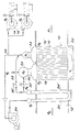
- the air heater designated as a whole by the reference 10 comprises two tubular bundles 16, 18, of methodical type, that is to say that the air to be heated circulates in their tubes against the current of corrosive combustion gases constituting the coolant.
- These tubular bundles 16, 18 are positioned in the flue 12 where the corrosive combustion products circulate, perpendicular to the tubes of the bundles 16, 18.
- the tubular bundles 16, 18 are supplied with air at a temperature ⁇ 0 via one or more fans such as 14, 14 ′, the air flowing from the first beam of the first beam 16 to the second beam 18, passing through a lower distribution box 20, before being discharged to the furnace of the thermal installation (not shown) by a collector 22.
- This fan 26 can either draw air directly from the atmosphere or be placed in bypass (broken line 28) on the supply circuit of the heater 10 by the fans 14, 14 ′.
- the discharge pressure of the fan 26 is much higher than the pressure prevailing at the inlet of the heater 10.
- the protective beam 24, 24 ′ is placed upstream of the last zone of the methodical heater 10, that is to say in front of the first tubes of the beam 18 in this heater and it is calculated in flow and on the surface so as to lower the temperature of the flue gases so that in maximum operating conditions of the thermal equipment located upstream (not shown in the figure), the temperature ⁇ 3 of the first tubes of the bundle 18 of the heater, is always lower at the critical temperature of corrosion by sodium and vanadium, this critical temperature being a function of the metallurgical quality of the tubes and the composition of the fumes.
- the hot air leaves the protective bundle 24, 24 ′ at a temperature ⁇ 5 and it is directed towards the manifold 22, by means of the pipe 30 on which a valve is mounted. 30 ′ which then feeds the oven, the entire heater operating with optimum efficiency.
- a constant exchange surface corresponds to a lowering of the flue gas temperature such that the temperature ⁇ 2 of the last tubes of the bundle 16 of the heater risks becoming lower than the temperature of the acid dew point, which would subject the tubes of the heater 10 to a risk of corrosion by the condensations of the oxidized sulfur compounds, contained in the fumes, which is precisely what the invention seeks to avoid. Consequently, the flow of hot air at temperature ⁇ 5 coming from the protective beam 24, 24 ′ is wholly or partly deflected towards the downstream zone of the manifold 34 bringing cold air at temperature ⁇ 0 to the heater 10.
- the air supplied to the tube bundle 16 of the heater 10 is preheated to a temperature ⁇ 1 > ⁇ 0, this temperature ⁇ 1 being such that the temperature ⁇ 2 of the skin of the tubes of the heater 10 is always higher than the temperature of the acid dew point of the fumes.
- the invention allows: on the one hand, to ensure a temperature ⁇ 1 for all regimes such as the skin temperature ⁇ 2 of the tubes of the bundle 16 of the heater 10 is always slightly higher than the temperature of the acid dew point of the fumes and on the other hand to maintain the temperature ⁇ 3 of the first plies of tubes of the bundle 18 of the heater 10, at a value which is always lower than the critical temperature of corrosion by sodium / vanadium.
- the invention therefore makes it possible to produce an air heater which eliminates the risks of corrosion at high temperature by sodium / vanadium salts and at low temperature by acidic condensations due to the presence of oxidized sulfur compounds in the fumes.
Landscapes
- Engineering & Computer Science (AREA)
- Chemical & Material Sciences (AREA)
- Combustion & Propulsion (AREA)
- Mechanical Engineering (AREA)
- General Engineering & Computer Science (AREA)
- Air Supply (AREA)
- Heat-Exchange Devices With Radiators And Conduit Assemblies (AREA)
Applications Claiming Priority (2)
| Application Number | Priority Date | Filing Date | Title |
|---|---|---|---|
| FR8804445A FR2629574B1 (fr) | 1988-04-05 | 1988-04-05 | Rechauffeur d'air pour atmospheres corrosives |
| FR8804445 | 1988-04-05 |
Publications (2)
| Publication Number | Publication Date |
|---|---|
| EP0337834A2 true EP0337834A2 (de) | 1989-10-18 |
| EP0337834A3 EP0337834A3 (de) | 1990-02-28 |
Family
ID=9364944
Family Applications (1)
| Application Number | Title | Priority Date | Filing Date |
|---|---|---|---|
| EP89400798A Withdrawn EP0337834A3 (de) | 1988-04-05 | 1989-03-21 | Lufterhitzer für korrosive Atmosphären |
Country Status (6)
| Country | Link |
|---|---|
| US (1) | US4949782A (de) |
| EP (1) | EP0337834A3 (de) |
| DE (1) | DE337834T1 (de) |
| ES (1) | ES2011217A4 (de) |
| FR (1) | FR2629574B1 (de) |
| GR (1) | GR890300176T1 (de) |
Cited By (2)
| Publication number | Priority date | Publication date | Assignee | Title |
|---|---|---|---|---|
| WO1998039599A1 (en) * | 1997-03-06 | 1998-09-11 | Siemens Westinghouse Power Corporation | Staged supplemental firing of high vanadium content fuel oils |
| CN105605604A (zh) * | 2016-03-10 | 2016-05-25 | 大唐贵州发耳发电有限公司 | 一种空预器防腐/防堵系统 |
Families Citing this family (6)
| Publication number | Priority date | Publication date | Assignee | Title |
|---|---|---|---|---|
| US5361827A (en) * | 1992-12-29 | 1994-11-08 | Combustion Engineering, Inc. | Economizer system for vapor generation apparatus |
| US5425502A (en) * | 1994-07-26 | 1995-06-20 | Yu Feng Enterprise Co., Ltd. | VAV air conditioning system with a by-pass air supply fan |
| DE19518323A1 (de) * | 1995-05-18 | 1996-11-21 | Calorifer Ag | Verfahren und Vorrichtung zum unterbrechungsfreien Wärmetausch |
| CN102230636B (zh) * | 2011-03-29 | 2015-09-30 | 宝钢工业炉工程技术有限公司 | 预热器金属换热管的低温保护装置 |
| CN103900396B (zh) * | 2012-12-26 | 2016-03-16 | 赵吉焕 | 减少白烟发生装置及利用其的废热及用水回收方法 |
| DE102015112220A1 (de) | 2015-07-27 | 2017-02-02 | Outotec (Finland) Oy | Verfahren und Anlage zum Kühlen eines SO 2 und/oder SO 3 und Spuren von Wasser enthaltenden Gases |
Family Cites Families (13)
| Publication number | Priority date | Publication date | Assignee | Title |
|---|---|---|---|---|
| US2947522A (en) * | 1955-05-12 | 1960-08-02 | Keller John Donald | Recuperators |
| GB955272A (en) * | 1960-01-19 | 1964-04-15 | Ind Companie Kleine Wefers Kon | Improvements in and relating to heat recuperators |
| SU565151A1 (ru) * | 1969-05-05 | 1977-07-15 | Центральное Конструкторское Бюро Главэнергоремонта | Воздухоподогреватель |
| SU848892A2 (ru) * | 1971-05-13 | 1981-07-23 | Центральное Конструкторское Бюроглавэнергоремонта | Воздухоподогреватель |
| SU992918A1 (ru) * | 1976-12-28 | 1983-01-30 | Научно-Производственное Объединение "Энергоцветмет" | Конвективный воздухоподогреватель |
| SU785595A1 (ru) * | 1979-02-12 | 1980-12-07 | Коммунарский горно-металлургический институт | Воздухоподогреватель |
| US4305455A (en) * | 1979-02-28 | 1981-12-15 | Lipets Adolf U | Multipass corrosion proof air heater |
| US4243096A (en) * | 1979-04-09 | 1981-01-06 | Lipets Adolf U | Multipass corrosion-proof air heater |
| FR2454598A1 (fr) * | 1979-04-18 | 1980-11-14 | Lipets Adolf | Rechauffeur d'air a plusieurs voies, resistant a la corrosion |
| CA1183833A (en) * | 1981-01-09 | 1985-03-12 | Keith W. Gilbert | Air preheater |
| SU1090978A2 (ru) * | 1982-07-29 | 1984-05-07 | Предприятие П/Я Р-6193 | Воздухоподогреватель |
| US4576226A (en) * | 1983-04-18 | 1986-03-18 | Lipets Adolf U | Multipass corrosion-proof air preheater |
| FR2545197B1 (fr) * | 1983-04-26 | 1988-04-15 | Lipets Adolf | Rechauffeur d'air a corps de chauffe multiples resistant a la corrosion |
-
1988
- 1988-04-05 FR FR8804445A patent/FR2629574B1/fr not_active Expired - Lifetime
-
1989
- 1989-03-21 DE DE198989400798T patent/DE337834T1/de active Pending
- 1989-03-21 EP EP89400798A patent/EP0337834A3/de not_active Withdrawn
- 1989-03-21 ES ES89400798T patent/ES2011217A4/es active Pending
- 1989-03-24 US US07/328,291 patent/US4949782A/en not_active Expired - Lifetime
-
1990
- 1990-10-31 GR GR89300176T patent/GR890300176T1/el unknown
Cited By (2)
| Publication number | Priority date | Publication date | Assignee | Title |
|---|---|---|---|---|
| WO1998039599A1 (en) * | 1997-03-06 | 1998-09-11 | Siemens Westinghouse Power Corporation | Staged supplemental firing of high vanadium content fuel oils |
| CN105605604A (zh) * | 2016-03-10 | 2016-05-25 | 大唐贵州发耳发电有限公司 | 一种空预器防腐/防堵系统 |
Also Published As
| Publication number | Publication date |
|---|---|
| DE337834T1 (de) | 1990-02-08 |
| EP0337834A3 (de) | 1990-02-28 |
| FR2629574A1 (fr) | 1989-10-06 |
| GR890300176T1 (en) | 1990-10-31 |
| ES2011217A4 (es) | 1990-01-01 |
| US4949782A (en) | 1990-08-21 |
| FR2629574B1 (fr) | 1992-03-20 |
Similar Documents
| Publication | Publication Date | Title |
|---|---|---|
| FI125247B (fi) | Koneistojärjestely vesikulkuneuvoon ja menetelmä vesikulkuneuvon koneistojärjestelyn käyttämiseksi | |
| EP2148935B1 (de) | Verfahren und vorrichtung zur erwärmung eines metallstreifens, insbesondere zu seiner glühung | |
| FI117804B (fi) | Järjestely ja menetelmä turbokompressorilla varustetun mäntämoottorin yhteydessä | |
| TWI526653B (zh) | 整合式分開蒸汽水盤管空氣加熱器及節熱器(iwe)、及改善鍋爐的節熱器的對數平均溫差之方法 | |
| FR2504409A1 (fr) | Dispositif de traitement de gaz s'appliquant a plusieurs chaudieres | |
| FR2498252A1 (fr) | Systeme de refroidissement pour une chemise interieure de chambre de combustion | |
| EP3112751A1 (de) | Abgasrückführungssystem, schiffskessel damit und abgasrückführungsverfahren | |
| FR2629574A1 (fr) | Rechauffeur d'air pour atmospheres corrosives | |
| JP5345671B2 (ja) | 船舶用機械装置 | |
| JP2012057860A (ja) | 排熱回収装置 | |
| EP3004571B1 (de) | Verfahren zur energieerzeugung durch verbrennung von stoffen sowie anlage zur durchführung des verfahrens | |
| JP2019090559A (ja) | ボイラ排ガス用熱交換器の温度制御装置 | |
| EP3473737B1 (de) | Durchlaufglühanlage | |
| JP2011094901A (ja) | ガスガスヒータ及びガスガスヒータの制御方法 | |
| CN114877345A (zh) | 一种炉排驱动机构冷却系统和焚烧炉 | |
| FR2543663A1 (fr) | Chaudiere de chauffage a condensation | |
| JP5234578B2 (ja) | 水冷ダクト | |
| FR2723632A1 (fr) | Dispositif d'echange de chaleur pour une chaudiere basse temperature | |
| BE1020814A5 (fr) | Dispositif aerodynamique de regulation de la temperature et de la pression dans un circuit de circulation de fluides. | |
| JP2014009835A (ja) | 排ガス処理装置 | |
| EP3710688B1 (de) | Antriebsstrang mit verbessertem schadstoffbeseitigungssystem | |
| FR2461197A1 (fr) | Procede et dispositif de recuperation de chaleur dans des fumees | |
| EP1681456A1 (de) | Anlage zur thermischen Regelung des in einen Motor eingelassenen Gases | |
| EP3408590B1 (de) | Gasrückführungsvorrichtung | |
| JP6620843B2 (ja) | 排熱回収システム、船舶 |
Legal Events
| Date | Code | Title | Description |
|---|---|---|---|
| PUAI | Public reference made under article 153(3) epc to a published international application that has entered the european phase |
Free format text: ORIGINAL CODE: 0009012 |
|
| AK | Designated contracting states |
Kind code of ref document: A2 Designated state(s): AT BE CH DE ES GB GR IT LI LU NL SE |
|
| ITCL | It: translation for ep claims filed |
Representative=s name: BARZANO' E ZANARDO MILANO S.P.A. |
|
| TCAT | At: translation of patent claims filed | ||
| TCNL | Nl: translation of patent claims filed | ||
| GBC | Gb: translation of claims filed (gb section 78(7)/1977) | ||
| PUAL | Search report despatched |
Free format text: ORIGINAL CODE: 0009013 |
|
| DET | De: translation of patent claims | ||
| AK | Designated contracting states |
Kind code of ref document: A3 Designated state(s): AT BE CH DE ES GB GR IT LI LU NL SE |
|
| 17P | Request for examination filed |
Effective date: 19900618 |
|
| STAA | Information on the status of an ep patent application or granted ep patent |
Free format text: STATUS: THE APPLICATION HAS BEEN WITHDRAWN |
|
| 18W | Application withdrawn |
Withdrawal date: 19910812 |