EP0337847A2 - Fermeture de décharge - Google Patents
Fermeture de décharge Download PDFInfo
- Publication number
- EP0337847A2 EP0337847A2 EP89400895A EP89400895A EP0337847A2 EP 0337847 A2 EP0337847 A2 EP 0337847A2 EP 89400895 A EP89400895 A EP 89400895A EP 89400895 A EP89400895 A EP 89400895A EP 0337847 A2 EP0337847 A2 EP 0337847A2
- Authority
- EP
- European Patent Office
- Prior art keywords
- tube end
- cap assembly
- end portion
- cap
- dispensing closure
- Prior art date
- Legal status (The legal status is an assumption and is not a legal conclusion. Google has not performed a legal analysis and makes no representation as to the accuracy of the status listed.)
- Granted
Links
Images


Classifications
-
- B—PERFORMING OPERATIONS; TRANSPORTING
- B65—CONVEYING; PACKING; STORING; HANDLING THIN OR FILAMENTARY MATERIAL
- B65D—CONTAINERS FOR STORAGE OR TRANSPORT OF ARTICLES OR MATERIALS, e.g. BAGS, BARRELS, BOTTLES, BOXES, CANS, CARTONS, CRATES, DRUMS, JARS, TANKS, HOPPERS, FORWARDING CONTAINERS; ACCESSORIES, CLOSURES, OR FITTINGS THEREFOR; PACKAGING ELEMENTS; PACKAGES
- B65D47/00—Closures with filling and discharging, or with discharging, devices
- B65D47/04—Closures with discharging devices other than pumps
- B65D47/20—Closures with discharging devices other than pumps comprising hand-operated members for controlling discharge
- B65D47/24—Closures with discharging devices other than pumps comprising hand-operated members for controlling discharge with poppet valves or lift valves, i.e. valves opening or closing a passageway by a relative motion substantially perpendicular to the plane of the seat
- B65D47/241—Closures with discharging devices other than pumps comprising hand-operated members for controlling discharge with poppet valves or lift valves, i.e. valves opening or closing a passageway by a relative motion substantially perpendicular to the plane of the seat the valve being opened or closed by actuating a cap-like element
- B65D47/242—Closures with discharging devices other than pumps comprising hand-operated members for controlling discharge with poppet valves or lift valves, i.e. valves opening or closing a passageway by a relative motion substantially perpendicular to the plane of the seat the valve being opened or closed by actuating a cap-like element moving helically
Definitions
- This invention relates to a tube closure device for dispensing products contained within the tube. More particularly, this invention relates to a dispensing closure device which has a recessed upper surface allowing the tube to be stored in an upright position on top of the closure member.
- the closure generally comprises a two-piece cap system.
- a first inner cap portion which includes a valve body and an outer threaded portion
- a second outer cap portion which includes an inner threaded portion, to engage the outer thread portion of the inner cap, and a valve stem engaging hole.
- the outer portion of the two-piece cap system threads over the inner portion, and by twisting the outer portion relative to the inner portion, the valve is thereby opened and closed. The twisting results in relative displacement between the outer and inner portions along the valve stem, thereby dislodging the valve stem from the hole in the outer cap member.
- the present invention proposes a two-piece dispensing closure which has a recessed top surface on the outer cap assembly. This recessed upper surface allows the closure and the attached tube to be stored in an upright position with the tube arranged on top of the closure device.
- the viscous tubed product is drawn by gravity to the end of the tube nearest the closure so that the product is readily dispensed immediately upon opening of the closure.
- storage in an upright position allows the product to be drawn completely from the tube so as to permit dispensing in a normal manner.
- the present invention also proposes a particular interrelationship between the threads of the respective cap and tube end. This relationship allows for maximum axial displacement between the cap and tube for minimal associated rotational displacement therebetween.
- a closure assembly according to the present invention is made up of two major portions, a tube end portion, and a cap assembly.
- the cap assembly and tube end portion interrelate to form a two-piece dispensing closure assembly.
- the cap assembly is formed with an end wall that is concave to a degree sufficient to provide clearance for the protruding valve stem and exterior valve body.
- a dispensing closure allows disposition of the closure and attached tube in an upright position wherein the viscous tubed product is arranged on top of and is drawn towards the closure assembly.
- Another object of this invention is to provide a dispensing closure wherein the amount of relative rotational displacement between the cap and tube and member is comparatively small for the corresponding degree of opening between the cap and tube end member.
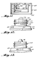
- FIGURE 1 illustrates the physical arrangement of a tubed product equipped with a dispensing closure according to the present invention.
- the combination tube and closure 1 comprises a closure assembly 2 located at one end of tube 4.
- FIGURES 2 and 3 illustrate end views of the closure and tube assembly in closed and open positions, respectively.
- FIGURE 4 illustrates the preferred method of storage of the tube and closure combination 1.
- the tubed product may be stored in an upright position on surface B wherein the closure assembly 2 provides stable support for tube 4.
- the closure assembly comprises the following major portions: a cap assembly 20 and a tube end portion 50.
- the cap assembly 20 and tube end portion 50 interact to form a two-piece dispensing closure assembly.
- Cap assembly 20 is made up of cap top portion 30 and side portion 24.
- Top portion 30 is characterized by an inwardly concave upper surface 32.
- Located on surface 32 is an upstanding exterior valve body 34.
- Valve body 34 interacts with valve stem 76 to seal and unseal the closure member.
- Top portion 30 also has two downwardly depending sleeves 39 and 31 located on its underside.
- Inner cap sleeve 39 in combination with the bottom surface of the inwardly concave surface 32 form the upper limits of cap chamber A.
- Inner cap sleeve 39 sealingly engages, in all relative positions of the cap and tube end portion, upstanding sleeve member 60 of the tube end portion 50. This sealing engagement between sleeves 39 and 60 prevents any product from escaping from the tube except when desired through exterior valve body 34 when the closure assembly is in the fully open position.
- the second sleeve which depends from the cap top portion 30 is outer cap sleeve 31.
- the inner surface of the outer cap sleeve 31 has a threaded portion 35 which engages the threaded portion 62 of upstanding sleeve member 60.
- the interrelated threads provide relative axial displacement between the cap and tube end portion when the cap is twisted.
- Side portion 24 has a peripheral notch 25 included along its lower most portion. Notch 25 engages stop block 54 located on a peripheral portion of tube end portion 50 when the fully open position of the closure is achieved. In this manner, sturdy blocking members of the cap and tube end portion engage to prevent overloosening of the cap from the tube end portion and thus preserve the shape of the cap and tube end portion in undistorted form.
- Cap upper portion 30 is connected to the cap side wall 24 at rim 38.
- the concave upper surface 32 of cap top portion 30 dips sufficiently to allow cap rim 38 to protrude beyond valve stem 76 and upstanding exterior valve body 34 so as to allow clearance between a supporting surface B and the protruding valve members.
- Tube end portion 50 is made up of tube end side walls 40, end wall 52, upstanding sleeve member 60 and valve stem 70.
- End wall 52 has upstanding sleeve member 60 connected thereto.
- Sleeve member 60 interacts with the two downwardly depending sleeves 39 and 31 of cap top portion 30.
- the threaded portion 35 of the outer cap sleeve 31 engages the threaded portion 62 of upstanding sleeve 60.
- the respective threaded portion 62 and threaded portion 35 cooperate such that twisting of cap assembly 20 relative to tube end portion 50 results in displacement of the cap assembly either away from or towards the tube end portion for a given relative rotation of the cap and tube end portions.
- the tube incorporates two threads 62 that start 180 degrees apart.
- the pitch on both threads is .250.
- the thread profile on both the cap and tube is that of a standard .125 pitch, 24mm thread. With the threads starting 180 degrees apart, the spacing between them, when they are parallel to one another, is the same as it would be if they were designed for a standard .125 pitch tube/cap engagement.
- This condition on the tube contains the thread on the cap and guides it through the raising and lowering of the cap.
- the tube and cap assembly of the present invention therefore benefits not only from the quick rise/fall of the .250 pitch thread, but also maintains control of the cap through the thread engagement.
- the .250 pitch thread on both the cap and tube allow an operator to "raise" the cap's exterior valve body (34) off the tube valve stem (76) the required amount with only one-quarter to one-third of a revolution of the cap.
- End wall 52 includes a passage containing surface 55.
- Passage containing surface 55 has located therein passages 56 which allow movement of the product through chamber A and past the valve assembly.
- Passage containing surface 55 supports valve stem 76.
- Valve stem 76 comprises a main body portion 72, tapered sealing surfaces 74, and a valve stem tip portion. The valve stem 76, and passage containing surface 55 are molded as integral parts of tube end portion 50.
- tapered sealing surfaces 74, of valve stem 76 interact with the inner surfaces of the cap valve body 34 to stop the movement of product through cap chamber A.
- surfaces 74 and 34 are no longer in contact and thus tubed product may pass through chamber A and past the open valve.
- FIGURE 4 illustrates the closure assembly oriented in an upright position on surface B.
- cap rim 38 protrudes sufficiently to provide clearance between surface B and valve stem 76 and upstanding exterior valve body 34.
- a tube equipped with a dispensing closure according to the present invention is easily stored in a nonuse upright position for ready and complete dispensing of the contained product.
- the closure assembly 2 may be injection molded from any suitable plastic molding material.
- the separate cap assembly and tube end portion, which together make up the closure assembly are each constructed as single integrally molded plastic pieces.
Landscapes
- Engineering & Computer Science (AREA)
- Mechanical Engineering (AREA)
- Closures For Containers (AREA)
- Containers And Packaging Bodies Having A Special Means To Remove Contents (AREA)
- Beans For Foods Or Fodder (AREA)
Priority Applications (1)
| Application Number | Priority Date | Filing Date | Title |
|---|---|---|---|
| AT89400895T ATE95135T1 (de) | 1988-04-13 | 1989-03-31 | Ausgabeverschluss. |
Applications Claiming Priority (2)
| Application Number | Priority Date | Filing Date | Title |
|---|---|---|---|
| US18107088A | 1988-04-13 | 1988-04-13 | |
| US181070 | 1988-04-13 |
Publications (3)
| Publication Number | Publication Date |
|---|---|
| EP0337847A2 true EP0337847A2 (fr) | 1989-10-18 |
| EP0337847A3 EP0337847A3 (en) | 1990-07-18 |
| EP0337847B1 EP0337847B1 (fr) | 1993-09-29 |
Family
ID=22662788
Family Applications (1)
| Application Number | Title | Priority Date | Filing Date |
|---|---|---|---|
| EP89400895A Expired - Lifetime EP0337847B1 (fr) | 1988-04-13 | 1989-03-31 | Fermeture de décharge |
Country Status (5)
| Country | Link |
|---|---|
| EP (1) | EP0337847B1 (fr) |
| AT (1) | ATE95135T1 (fr) |
| CA (1) | CA1319649C (fr) |
| DE (1) | DE68909474T2 (fr) |
| ES (1) | ES2044159T3 (fr) |
Cited By (1)
| Publication number | Priority date | Publication date | Assignee | Title |
|---|---|---|---|---|
| EP0690008A3 (fr) * | 1994-07-01 | 1997-02-26 | Duering Ag | Fermeture de bouteille à vis |
Family Cites Families (4)
| Publication number | Priority date | Publication date | Assignee | Title |
|---|---|---|---|---|
| US3175741A (en) * | 1964-03-12 | 1965-03-30 | Product Design & Engineering I | Closure and dispensing cap for the neck of a container |
| US3572559A (en) * | 1968-02-16 | 1971-03-30 | Morton B Stull | Multiposition dispensing cap |
| ES378747A1 (es) * | 1969-11-14 | 1972-06-16 | American Can Co | Nuevo sistema de cierre a presion para recipientes. |
| US4383623A (en) * | 1981-03-17 | 1983-05-17 | Ethyl Products Company | Dispensing closure with stationary axial plug |
-
1989
- 1989-03-31 ES ES89400895T patent/ES2044159T3/es not_active Expired - Lifetime
- 1989-03-31 AT AT89400895T patent/ATE95135T1/de not_active IP Right Cessation
- 1989-03-31 EP EP89400895A patent/EP0337847B1/fr not_active Expired - Lifetime
- 1989-03-31 DE DE89400895T patent/DE68909474T2/de not_active Expired - Fee Related
- 1989-04-12 CA CA000596545A patent/CA1319649C/fr not_active Expired - Fee Related
Cited By (1)
| Publication number | Priority date | Publication date | Assignee | Title |
|---|---|---|---|---|
| EP0690008A3 (fr) * | 1994-07-01 | 1997-02-26 | Duering Ag | Fermeture de bouteille à vis |
Also Published As
| Publication number | Publication date |
|---|---|
| DE68909474T2 (de) | 1994-02-03 |
| DE68909474D1 (de) | 1993-11-04 |
| EP0337847B1 (fr) | 1993-09-29 |
| ATE95135T1 (de) | 1993-10-15 |
| ES2044159T3 (es) | 1994-01-01 |
| CA1319649C (fr) | 1993-06-29 |
| EP0337847A3 (en) | 1990-07-18 |
Similar Documents
| Publication | Publication Date | Title |
|---|---|---|
| US4964548A (en) | Dispensing closure having an interior sealing sleeve, a threaded sleeve engaging a threaded tube, and stop blocks limiting twisting of the closure cap | |
| RU2094342C1 (ru) | Контейнер с крышкой | |
| US5067624A (en) | Plastic closure for containers | |
| US5588546A (en) | Closure with stay-open lid | |
| AU713638B2 (en) | One-piece dispensing system and method for making same | |
| US4832238A (en) | Oil spout | |
| US5388712A (en) | Squeeze bottle top with integral closure holder | |
| US4616768A (en) | Discharge barrier for collapsible tubes | |
| US6039218A (en) | Tamper-evident closure with abutment | |
| US4778071A (en) | Closure with snap type hinge | |
| US3216630A (en) | Closure for containers | |
| US4635823A (en) | Dispensing closure construction | |
| US5873493A (en) | Integrally molded measurer/dispenser | |
| EP0208413A2 (fr) | Dispositif de fermeture muni d'un capuchon avec une charnière à effet de ressort | |
| US20070284399A1 (en) | A closure assembly having a spout with a memory band for spout directing | |
| WO1995020527A1 (fr) | Bouchon de fermeture etanche pour recipients | |
| US4491219A (en) | Container for two-component systems | |
| HUT71857A (en) | Pouring stopper for container | |
| US4569456A (en) | Sealed container with replaceable plug insert | |
| US4373561A (en) | Sump oil draining and collecting device | |
| US5961010A (en) | Dispensing beverage closure | |
| US5419467A (en) | Two-piece pouring spout with dome-shaped nozzle | |
| US5788120A (en) | Spout for a frozen dessert bag | |
| US7513388B2 (en) | Retractable straw device | |
| US20080277503A1 (en) | Flow limiting bottle cap |
Legal Events
| Date | Code | Title | Description |
|---|---|---|---|
| PUAI | Public reference made under article 153(3) epc to a published international application that has entered the european phase |
Free format text: ORIGINAL CODE: 0009012 |
|
| AK | Designated contracting states |
Kind code of ref document: A2 Designated state(s): AT BE CH DE ES FR GB GR IT LI LU NL SE |
|
| PUAL | Search report despatched |
Free format text: ORIGINAL CODE: 0009013 |
|
| AK | Designated contracting states |
Kind code of ref document: A3 Designated state(s): AT BE CH DE ES FR GB GR IT LI LU NL SE |
|
| 17P | Request for examination filed |
Effective date: 19901214 |
|
| 17Q | First examination report despatched |
Effective date: 19920624 |
|
| GRAA | (expected) grant |
Free format text: ORIGINAL CODE: 0009210 |
|
| RAP1 | Party data changed (applicant data changed or rights of an application transferred) |
Owner name: MCCORMICK & COMPANY, INC. |
|
| AK | Designated contracting states |
Kind code of ref document: B1 Designated state(s): AT BE CH DE ES FR GB GR IT LI LU NL SE |
|
| REF | Corresponds to: |
Ref document number: 95135 Country of ref document: AT Date of ref document: 19931015 Kind code of ref document: T |
|
| REF | Corresponds to: |
Ref document number: 68909474 Country of ref document: DE Date of ref document: 19931104 |
|
| ET | Fr: translation filed | ||
| ITF | It: translation for a ep patent filed | ||
| REG | Reference to a national code |
Ref country code: ES Ref legal event code: FG2A Ref document number: 2044159 Country of ref document: ES Kind code of ref document: T3 |
|
| REG | Reference to a national code |
Ref country code: GR Ref legal event code: FG4A Free format text: 3010242 |
|
| PGFP | Annual fee paid to national office [announced via postgrant information from national office to epo] |
Ref country code: FR Payment date: 19940310 Year of fee payment: 6 |
|
| PGFP | Annual fee paid to national office [announced via postgrant information from national office to epo] |
Ref country code: AT Payment date: 19940314 Year of fee payment: 6 |
|
| PGFP | Annual fee paid to national office [announced via postgrant information from national office to epo] |
Ref country code: SE Payment date: 19940316 Year of fee payment: 6 |
|
| PGFP | Annual fee paid to national office [announced via postgrant information from national office to epo] |
Ref country code: GB Payment date: 19940321 Year of fee payment: 6 |
|
| PGFP | Annual fee paid to national office [announced via postgrant information from national office to epo] |
Ref country code: DE Payment date: 19940323 Year of fee payment: 6 Ref country code: CH Payment date: 19940323 Year of fee payment: 6 |
|
| PGFP | Annual fee paid to national office [announced via postgrant information from national office to epo] |
Ref country code: ES Payment date: 19940329 Year of fee payment: 6 |
|
| PGFP | Annual fee paid to national office [announced via postgrant information from national office to epo] |
Ref country code: GR Payment date: 19940330 Year of fee payment: 6 |
|
| PGFP | Annual fee paid to national office [announced via postgrant information from national office to epo] |
Ref country code: NL Payment date: 19940331 Year of fee payment: 6 Ref country code: LU Payment date: 19940331 Year of fee payment: 6 |
|
| PGFP | Annual fee paid to national office [announced via postgrant information from national office to epo] |
Ref country code: BE Payment date: 19940427 Year of fee payment: 6 |
|
| EPTA | Lu: last paid annual fee | ||
| PLBE | No opposition filed within time limit |
Free format text: ORIGINAL CODE: 0009261 |
|
| STAA | Information on the status of an ep patent application or granted ep patent |
Free format text: STATUS: NO OPPOSITION FILED WITHIN TIME LIMIT |
|
| 26N | No opposition filed | ||
| EAL | Se: european patent in force in sweden |
Ref document number: 89400895.2 |
|
| PG25 | Lapsed in a contracting state [announced via postgrant information from national office to epo] |
Ref country code: LU Free format text: LAPSE BECAUSE OF NON-PAYMENT OF DUE FEES Effective date: 19950331 Ref country code: LI Effective date: 19950331 Ref country code: GB Effective date: 19950331 Ref country code: CH Effective date: 19950331 Ref country code: BE Effective date: 19950331 Ref country code: AT Effective date: 19950331 |
|
| PG25 | Lapsed in a contracting state [announced via postgrant information from national office to epo] |
Ref country code: SE Effective date: 19950401 Ref country code: ES Free format text: LAPSE BECAUSE OF NON-PAYMENT OF DUE FEES Effective date: 19950401 |
|
| BERE | Be: lapsed |
Owner name: MCCORMICK & CY INC. Effective date: 19950331 |
|
| PG25 | Lapsed in a contracting state [announced via postgrant information from national office to epo] |
Ref country code: GR Free format text: THE PATENT HAS BEEN ANNULLED BY A DECISION OF A NATIONAL AUTHORITY Effective date: 19950930 |
|
| PG25 | Lapsed in a contracting state [announced via postgrant information from national office to epo] |
Ref country code: NL Effective date: 19951001 |
|
| GBPC | Gb: european patent ceased through non-payment of renewal fee |
Effective date: 19950331 |
|
| PG25 | Lapsed in a contracting state [announced via postgrant information from national office to epo] |
Ref country code: FR Free format text: LAPSE BECAUSE OF NON-PAYMENT OF DUE FEES Effective date: 19951130 |
|
| REG | Reference to a national code |
Ref country code: CH Ref legal event code: PL Ref country code: GR Ref legal event code: MM2A Free format text: 3010242 |
|
| NLV4 | Nl: lapsed or anulled due to non-payment of the annual fee |
Effective date: 19951001 |
|
| PG25 | Lapsed in a contracting state [announced via postgrant information from national office to epo] |
Ref country code: DE Effective date: 19951201 |
|
| EUG | Se: european patent has lapsed |
Ref document number: 89400895.2 |
|
| REG | Reference to a national code |
Ref country code: FR Ref legal event code: ST |
|
| REG | Reference to a national code |
Ref country code: ES Ref legal event code: FD2A Effective date: 19990301 |
|
| PG25 | Lapsed in a contracting state [announced via postgrant information from national office to epo] |
Ref country code: IT Free format text: LAPSE BECAUSE OF NON-PAYMENT OF DUE FEES;WARNING: LAPSES OF ITALIAN PATENTS WITH EFFECTIVE DATE BEFORE 2007 MAY HAVE OCCURRED AT ANY TIME BEFORE 2007. THE CORRECT EFFECTIVE DATE MAY BE DIFFERENT FROM THE ONE RECORDED. Effective date: 20050331 |