EP0337875A1 - Tester mit Kontaktpunkt und zurückziehbarer Schutzhülse - Google Patents
Tester mit Kontaktpunkt und zurückziehbarer Schutzhülse Download PDFInfo
- Publication number
- EP0337875A1 EP0337875A1 EP89400989A EP89400989A EP0337875A1 EP 0337875 A1 EP0337875 A1 EP 0337875A1 EP 89400989 A EP89400989 A EP 89400989A EP 89400989 A EP89400989 A EP 89400989A EP 0337875 A1 EP0337875 A1 EP 0337875A1
- Authority
- EP
- European Patent Office
- Prior art keywords
- unlocking member
- protective sheath
- tester according
- insulating material
- elastically deformable
- Prior art date
- Legal status (The legal status is an assumption and is not a legal conclusion. Google has not performed a legal analysis and makes no representation as to the accuracy of the status listed.)
- Granted
Links
- 230000001681 protective effect Effects 0.000 claims abstract description 41
- 239000011810 insulating material Substances 0.000 claims abstract description 24
- 210000004027 cell Anatomy 0.000 description 4
- 230000001360 synchronised effect Effects 0.000 description 2
- 208000031968 Cadaver Diseases 0.000 description 1
- 238000004026 adhesive bonding Methods 0.000 description 1
- 230000000903 blocking effect Effects 0.000 description 1
- 230000000295 complement effect Effects 0.000 description 1
- 239000004020 conductor Substances 0.000 description 1
- 238000003780 insertion Methods 0.000 description 1
- 230000037431 insertion Effects 0.000 description 1
- 238000002955 isolation Methods 0.000 description 1
- 238000000465 moulding Methods 0.000 description 1
- 210000000056 organ Anatomy 0.000 description 1
- 239000000523 sample Substances 0.000 description 1
- 238000003466 welding Methods 0.000 description 1
Images

Classifications
-
- G—PHYSICS
- G01—MEASURING; TESTING
- G01R—MEASURING ELECTRIC VARIABLES; MEASURING MAGNETIC VARIABLES
- G01R1/00—Details of instruments or arrangements of the types included in groups G01R5/00 - G01R13/00 and G01R31/00
- G01R1/02—General constructional details
- G01R1/06—Measuring leads; Measuring probes
- G01R1/067—Measuring probes
- G01R1/06788—Hand-held or hand-manipulated probes, e.g. for oscilloscopes or for portable test instruments
Definitions
- the present invention relates generally to testers of the type comprising, carried by a body of insulating material, a test tip suitable for enabling the establishment of a contact, for example for checking the presence, or not, of a tension.
- a protective sheath which, against elastic return means, is mounted movable between a deployed position of rest, for which it extends beyond the end of the probe tip, and a retracted service position, for which it at least partially releases the latter.
- the touch tip is normally inaccessible at rest.
- this unlocking is obtained by rotating the protective sheath around its axis.
- this implementation involves the execution, in a synchronous manner, of two distinct movements, one, of rotation, necessary for unlocking the protective sleeve, the other, for translation, necessary for its passage from its deployed position from rest to its retracted service position.
- This implementation difficulty increases if, for the voltage control to be carried out, and as is relatively frequently the case, two testers are to be handled at the same time.
- the unlocking of the protective sheath is obtained by exerting a push on an unlocking member which, specifically provided for this purpose, is capable of enabling it, and only of enabling it, to be released. .
- the touch tip being released only during the contact to be made, the user does not see it in advance, which does not facilitate the execution of this contact and on the contrary makes it difficult. this execution.
- the present invention generally relates to a provision for eliminating these drawbacks.
- a tester of the kind comprising, carried by a body of insulating material, a test point suitable for allowing the establishment of contact, with, surrounding said test point, a protective sheath who, contrary to elastic return means, is mounted to move between a deployed rest position, for which it extends beyond the end of the test tip, and a retracted service position, for which it at least partially releases it.
- a protective sheath who, contrary to elastic return means, is mounted to move between a deployed rest position, for which it extends beyond the end of the test tip, and a retracted service position, for which it at least partially releases it.
- the tester according to the invention is therefore particularly easy and convenient to use.
- It also has an advantageously ergonomic shape, this shape being able, moreover, to be chosen so as to promote compliance with the center distance corresponding to the international spacing of the pins or cells of the usual current sockets.
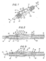
- FIGS. 1-10 illustrate, by way of example, the application of the invention to a "wire-based" tester, that is to say to a tester placed at the end of a cord or other electrical conductor 10 suitable for its Implementation.
- this tester can just as easily be permanently fixed to any device, and in particular to any voltage check block.
- the tester comprises, carried by a body of insulating material 11, a test point 12 suitable for allowing the establishment of contact, with, surrounding this test point 12, a sheath of protection 13 which, against elastic return means, constituted, in the embodiment shown, by a spring of the coil spring type 14, is mounted movable between a deployed position of rest, FIG. 2, for which it extends beyond the end of the test tip 12, and a retracted service position, FIG. 9, for which it at least partially releases the latter.
- the end, thus capable of being released, of the test tip 12 is suitable for allowing frontal contact, either at the end, at its own end 15, or intermediate, in favor of 'a generally frustoconical shoulder 16 slightly set back relative to this end 15, and, furthermore, between two shoulders, in this embodiment, set back, still, with respect to the generally frustoconical shoulder 16 preceding, a cage radially elastically deformable 17, it is also capable of allowing lateral contact.
- test tip 12 is in electrical connection with the conductive core of the cord 10, and on the assembly is overmolded a sleeve of insulating material 19.
- the spring 14 extends between the protective sheath 13 and this sleeve 19, around the test tip 12.
- the body of insulating material 11 is, moreover, formed of two shells 11A, 11B, one upper, the other lower, suitably facing one another, and suitably secured l to one another, for example by welding or gluing.
- these shells 11A, 11B jointly enclose the sleeve of insulating material 19.
- the lower shell 11B forms, in isolation, around the test tip 12 and the protective sheath 13 surrounding the latter, a tubular nose 20.
- the upper shell 11A therefore in a way only forms a cover for the lower shell 11B.
- the protective sheath 13 which is slidably mounted in the tubular nose 20 of the body of insulating material 11, is lockable in the deployed rest position under the control of an unlocking member 22 which, at the disposal of the user, is suitable for allowing its release.
- this unlocking member 22 is also suitable for ensuring the movement of the protective sheath 13 from its deployed rest position to its retracted service position.
- it is in the form of a push button, projecting from the upper surface of the upper shell 11A of the body of insulating material 11.
- this unlocking member 22 has, transversely, each disposed respectively on either side of a ridge 23, two depressions 24, 25, with a largely rounded profile, and with concavities oriented slightly in oblique to each other, the most forward depression, the one located on the side of the nose 20, in this case the depression 24, being in practice that intended to allow to exert an action on this organ of unlocking 22.
- the unlocking member 22 is axially linked to the protective sheath 13.
- the unlocking member 22 is connected to the protective sheath 13 by an elastically deformable tongue 27 formed by means of a puncture 28 in this protective sheath 13.
- the notch 29 of the elastically deformable tongue 27 extends transversely, and it belongs, in practice, to a development 32 formed by this elastically deformable tongue 27 at its free end.
- This opening 32 extends both transversely, on either side of the current part of the elastically deformable tongue 27, so that, in plan, the latter generally has a configuration in T, that radially, being projecting , in the direction opposite to the axis of the assembly, on the outer surface of this elastically deformable tongue 27.
- This opening 32 forms an inclined face, oriented in the direction opposite to the cord 10, and it is that of its transverse edges which is closest to the cord 10 which forms the notch 29.
- the notch 30 of the body of insulating material 11 belongs to one of the edges of a recess 33 provided in hollow on its inner surface, this recess 33, which is generally of quadrangular outline, being in practice a blind recess affecting in hollow the lower surface of its upper shell 11A.
- the unlocking member 22 is connected to the elastically deformable tongue 27 by a foot 34, which passes through the body of insulating material 11, and, more precisely, its upper shell 11A, by means of a slot 35 provided longitudinally on this upper shell 11A, parallel to the axis of the assembly.
- this foot 34 is established in line with the opening 32 of the elastically deformable tongue 27, and if it has, longitudinally, the same dimension as the latter, it is, transversely, of smaller dimension.
- This foot 34 interrupts, in its median zone, the notch 29 of the elastically deformable tongue 27, and, likewise, the slot 35 interrupts, in its median zone, the notch 30 of the body of insulating material 11.
- the unlocking member 22 extends in overhang, in the direction of the cord 10, counting from this foot 34.
- it is guided laterally, parallel to the axis of the assembly.
- the upper shell 11A of the body of insulating material 11 has, to do this, projecting from its outer surface, each arranged respectively on either side of this unlocking member 22, two flanges 36 which , in practice, join each other in a U on the side of the cord 10.
- the expansion 32 which this elastically deformable tongue 27 forms is normally engaged, by its upper part, in the recess 33, of which it is complementary, of the body of insulating material 11.
- this body of insulating material 11 is given a width equal to twice the international distance for the pins or cells of the usual current sockets, ie substantially 19 mm.
- Two testers according to the invention can thus advantageously be used side by side for simultaneous contact on two of such cells or two of such pins.
Landscapes
- Physics & Mathematics (AREA)
- General Physics & Mathematics (AREA)
- Measuring Leads Or Probes (AREA)
- Accommodation For Nursing Or Treatment Tables (AREA)
Applications Claiming Priority (2)
| Application Number | Priority Date | Filing Date | Title |
|---|---|---|---|
| FR8804953 | 1988-04-14 | ||
| FR8804953A FR2630219B1 (fr) | 1988-04-14 | 1988-04-14 | Testeur a pointe de touche et fourreau de protection retractable |
Publications (2)
| Publication Number | Publication Date |
|---|---|
| EP0337875A1 true EP0337875A1 (de) | 1989-10-18 |
| EP0337875B1 EP0337875B1 (de) | 1992-12-09 |
Family
ID=9365315
Family Applications (1)
| Application Number | Title | Priority Date | Filing Date |
|---|---|---|---|
| EP19890400989 Expired - Lifetime EP0337875B1 (de) | 1988-04-14 | 1989-04-11 | Tester mit Kontaktpunkt und zurückziehbarer Schutzhülse |
Country Status (4)
| Country | Link |
|---|---|
| EP (1) | EP0337875B1 (de) |
| DE (1) | DE68903776T2 (de) |
| ES (1) | ES2036355T3 (de) |
| FR (1) | FR2630219B1 (de) |
Cited By (6)
| Publication number | Priority date | Publication date | Assignee | Title |
|---|---|---|---|---|
| EP0625709A1 (de) * | 1993-05-18 | 1994-11-23 | MDM Elektrosystem AG | Prüfspitze für elektrische Messgeräte, insbesondere Spannungsmesser |
| FR2774771A1 (fr) * | 1998-02-10 | 1999-08-13 | Chauvin Arnoux | Dispositif formant testeur a pointe de touche retractable |
| JP2011191281A (ja) * | 2010-03-17 | 2011-09-29 | Hioki Ee Corp | 測定用プローブ |
| EP2211188A3 (de) * | 2009-01-22 | 2011-11-02 | Fluke Corporation | Testsonde mit einziehbarer Isolierhülse |
| EP3141911A1 (de) * | 2015-09-08 | 2017-03-15 | Hioki Denki Kabushiki Kaisha | Spannungsdetektionssonde und messvorrichtung |
| JP2020003392A (ja) * | 2018-06-29 | 2020-01-09 | 日置電機株式会社 | テストリードおよび測定装置 |
Families Citing this family (4)
| Publication number | Priority date | Publication date | Assignee | Title |
|---|---|---|---|---|
| JPH10239350A (ja) * | 1997-02-25 | 1998-09-11 | Seiko Epson Corp | 計測装置のテストプローブおよびこれを備えたテスター |
| DE19750280A1 (de) * | 1997-11-13 | 1999-05-20 | Erich Rasche | Meßelektrode zur reproduzierbaren Messung an Arealen der menschlichen Haut, vornehmlich an Akupunkturpunkten mit und ohne Stromeinwirkungen |
| DE102012004340B4 (de) * | 2012-03-07 | 2017-04-06 | GMC-I Messtechnik GmbH | Messspitze |
| DE102014108041B4 (de) | 2014-06-06 | 2016-06-02 | Wago Verwaltungsgesellschaft Mbh | Tastkopf |
Citations (2)
| Publication number | Priority date | Publication date | Assignee | Title |
|---|---|---|---|---|
| US4041380A (en) * | 1976-03-12 | 1977-08-09 | Kastar, Inc. | Multi-function tester with removable circuit cartridge |
| US4263547A (en) * | 1978-05-10 | 1981-04-21 | The Superior Electric Company | Test probe and terminal |
-
1988
- 1988-04-14 FR FR8804953A patent/FR2630219B1/fr not_active Expired - Lifetime
-
1989
- 1989-04-11 EP EP19890400989 patent/EP0337875B1/de not_active Expired - Lifetime
- 1989-04-11 DE DE1989603776 patent/DE68903776T2/de not_active Expired - Fee Related
- 1989-04-11 ES ES89400989T patent/ES2036355T3/es not_active Expired - Lifetime
Patent Citations (2)
| Publication number | Priority date | Publication date | Assignee | Title |
|---|---|---|---|---|
| US4041380A (en) * | 1976-03-12 | 1977-08-09 | Kastar, Inc. | Multi-function tester with removable circuit cartridge |
| US4263547A (en) * | 1978-05-10 | 1981-04-21 | The Superior Electric Company | Test probe and terminal |
Cited By (10)
| Publication number | Priority date | Publication date | Assignee | Title |
|---|---|---|---|---|
| EP0625709A1 (de) * | 1993-05-18 | 1994-11-23 | MDM Elektrosystem AG | Prüfspitze für elektrische Messgeräte, insbesondere Spannungsmesser |
| AU672287B2 (en) * | 1993-05-18 | 1996-09-26 | Mdm Elektrosystem Ag | Test probe for electrical measuring instruments, particularly for voltmeters |
| FR2774771A1 (fr) * | 1998-02-10 | 1999-08-13 | Chauvin Arnoux | Dispositif formant testeur a pointe de touche retractable |
| EP0936468A1 (de) * | 1998-02-10 | 1999-08-18 | Chauvin Arnoux | Prüfsonde mit einziehbarer Tastspitze |
| EP2211188A3 (de) * | 2009-01-22 | 2011-11-02 | Fluke Corporation | Testsonde mit einziehbarer Isolierhülse |
| CN101788574B (zh) * | 2009-01-22 | 2014-04-16 | 弗卢克公司 | 具有可伸缩的绝缘套筒的测试导线探针 |
| JP2011191281A (ja) * | 2010-03-17 | 2011-09-29 | Hioki Ee Corp | 測定用プローブ |
| EP3141911A1 (de) * | 2015-09-08 | 2017-03-15 | Hioki Denki Kabushiki Kaisha | Spannungsdetektionssonde und messvorrichtung |
| US10041977B2 (en) | 2015-09-08 | 2018-08-07 | Hioki Denki Kabushiki Kaisha | Voltage detecting probe and measuring device |
| JP2020003392A (ja) * | 2018-06-29 | 2020-01-09 | 日置電機株式会社 | テストリードおよび測定装置 |
Also Published As
| Publication number | Publication date |
|---|---|
| EP0337875B1 (de) | 1992-12-09 |
| FR2630219A1 (fr) | 1989-10-20 |
| DE68903776D1 (de) | 1993-01-21 |
| DE68903776T2 (de) | 1993-04-08 |
| FR2630219B1 (fr) | 1990-08-17 |
| ES2036355T3 (es) | 1993-05-16 |
Similar Documents
| Publication | Publication Date | Title |
|---|---|---|
| EP0337875B1 (de) | Tester mit Kontaktpunkt und zurückziehbarer Schutzhülse | |
| EP0634252B1 (de) | Taschenmesser mit einer verriegelbaren Klinge und einer Druckknopfentriegelungsvorrichtung | |
| EP0038745B1 (de) | Anordnung mit einer Kontaktklemme und mit einem mit dieser Klemme zusammenwirkenden Stecker zum unterbrechungsfreien Verbinden mit einem die Klemme tragenden Schaltkreis | |
| EP0580468A1 (de) | Verbindungsanordnung mit Bajonettverschluss | |
| FR2713833A1 (fr) | Organe femelle de contact électrique et élément de boîtier de connecteur électrique destiné à recevoir un tel organe. | |
| FR2923090A1 (fr) | Connecteur electrique miniature a elements de contact extractibles et outil associe de deverrouillage et d'extraction des contacts | |
| EP0133068A1 (de) | Sicherheitsschloss | |
| FR2579381A2 (fr) | Contact electrique a pression a pouvoir de fermeture et d'ouverture incorpore | |
| FR2614921A1 (fr) | Dispositif de securite a l'arrachement et a l'enfoncement d'une piece emmanchee dans une autre piece, et ensemble formant serrure de surete equipe de ce dispositif | |
| FR2563383A1 (fr) | Fiche de prise de courant a element de traction | |
| EP0884806B1 (de) | Elektrischer Steckverbinder mit verbessertem Sicherheitskontakt | |
| BE1006306A3 (fr) | Fiche presentant une structure specialement concue de broches. | |
| EP0936468A1 (de) | Prüfsonde mit einziehbarer Tastspitze | |
| EP1164379A1 (de) | Spannungstester für elektrische Steckdose und Steckdose für selbigen | |
| FR2722620A3 (fr) | Outil de deblocage | |
| CH677722A5 (en) | Bracelet fastener with two elements superposed | |
| FR2610561A1 (fr) | Cle a cliquet destinee a serrer une vis notamment dans un connecteur de cable electrique | |
| FR2697194A1 (fr) | Couteau à lame rétractable et sécable. | |
| EP0949719B1 (de) | Elektrischer Steckverbinder für ein Fahrer- oder Beifahrerairbagsystem in Kraftfahrzeugen | |
| EP0403359B1 (de) | Auslöseteil für einen elektrischen Schalter in Fahrtrichtungsblinkanlagen eines Kraftfahrzeuges | |
| FR2596540A1 (fr) | Tirette de commande a distance | |
| FR2552007A1 (fr) | Perfectionnements au dispositif de crantage des couteaux a lame retractable | |
| EP1187154B1 (de) | Elektrisches Gerät mit Druckknopf | |
| FR2517239A1 (fr) | Cle a levier mobile, avec embout rapporte, destinee notamment au serrage ou desserrage des ecrous de fixation des roues de vehicules automobiles | |
| EP0327460A1 (de) | Elektrischer Schalter mit automatischer Ausschaltung, insbesondere Differentialschutz |
Legal Events
| Date | Code | Title | Description |
|---|---|---|---|
| PUAI | Public reference made under article 153(3) epc to a published international application that has entered the european phase |
Free format text: ORIGINAL CODE: 0009012 |
|
| AK | Designated contracting states |
Kind code of ref document: A1 Designated state(s): DE ES IT |
|
| 17P | Request for examination filed |
Effective date: 19891223 |
|
| 17Q | First examination report despatched |
Effective date: 19920416 |
|
| GRAA | (expected) grant |
Free format text: ORIGINAL CODE: 0009210 |
|
| AK | Designated contracting states |
Kind code of ref document: B1 Designated state(s): DE ES IT |
|
| REF | Corresponds to: |
Ref document number: 68903776 Country of ref document: DE Date of ref document: 19930121 |
|
| ITF | It: translation for a ep patent filed | ||
| REG | Reference to a national code |
Ref country code: ES Ref legal event code: FG2A Ref document number: 2036355 Country of ref document: ES Kind code of ref document: T3 |
|
| PLBE | No opposition filed within time limit |
Free format text: ORIGINAL CODE: 0009261 |
|
| STAA | Information on the status of an ep patent application or granted ep patent |
Free format text: STATUS: NO OPPOSITION FILED WITHIN TIME LIMIT |
|
| 26N | No opposition filed | ||
| PGFP | Annual fee paid to national office [announced via postgrant information from national office to epo] |
Ref country code: DE Payment date: 20060407 Year of fee payment: 18 |
|
| PGFP | Annual fee paid to national office [announced via postgrant information from national office to epo] |
Ref country code: ES Payment date: 20060421 Year of fee payment: 18 |
|
| PG25 | Lapsed in a contracting state [announced via postgrant information from national office to epo] |
Ref country code: DE Free format text: LAPSE BECAUSE OF NON-PAYMENT OF DUE FEES Effective date: 20071101 |
|
| REG | Reference to a national code |
Ref country code: ES Ref legal event code: FD2A Effective date: 20070412 |
|
| PGFP | Annual fee paid to national office [announced via postgrant information from national office to epo] |
Ref country code: IT Payment date: 20080419 Year of fee payment: 20 |
|
| PG25 | Lapsed in a contracting state [announced via postgrant information from national office to epo] |
Ref country code: ES Free format text: LAPSE BECAUSE OF NON-PAYMENT OF DUE FEES Effective date: 20070412 |