EP0337904A1 - Vorrichtung mit selbstregelnder verstellbarer Flosse besonders für ein Segelbrett oder dergleichen - Google Patents
Vorrichtung mit selbstregelnder verstellbarer Flosse besonders für ein Segelbrett oder dergleichen Download PDFInfo
- Publication number
- EP0337904A1 EP0337904A1 EP89420128A EP89420128A EP0337904A1 EP 0337904 A1 EP0337904 A1 EP 0337904A1 EP 89420128 A EP89420128 A EP 89420128A EP 89420128 A EP89420128 A EP 89420128A EP 0337904 A1 EP0337904 A1 EP 0337904A1
- Authority
- EP
- European Patent Office
- Prior art keywords
- fin
- arm
- directional
- pinion
- teeth
- Prior art date
- Legal status (The legal status is an assumption and is not a legal conclusion. Google has not performed a legal analysis and makes no representation as to the accuracy of the status listed.)
- Withdrawn
Links
Images



Classifications
-
- B—PERFORMING OPERATIONS; TRANSPORTING
- B63—SHIPS OR OTHER WATERBORNE VESSELS; RELATED EQUIPMENT
- B63B—SHIPS OR OTHER WATERBORNE VESSELS; EQUIPMENT FOR SHIPPING
- B63B32/00—Water sports boards; Accessories therefor
- B63B32/60—Board appendages, e.g. fins, hydrofoils or centre boards
- B63B32/64—Adjustable, e.g. by adding sections, by removing sections or by changing orientation or profile
-
- B—PERFORMING OPERATIONS; TRANSPORTING
- B63—SHIPS OR OTHER WATERBORNE VESSELS; RELATED EQUIPMENT
- B63B—SHIPS OR OTHER WATERBORNE VESSELS; EQUIPMENT FOR SHIPPING
- B63B35/00—Vessels or similar floating structures specially adapted for specific purposes and not otherwise provided for
- B63B2035/009—Wind propelled vessels comprising arrangements, installations or devices specially adapted therefor, other than wind propulsion arrangements, installations, or devices, such as sails, running rigging, or the like, and other than sailboards or the like or related equipment
Definitions
- the present invention relates to a device relating to a directional fin of the kind used on a windsurfing board, on a dinghy, on a floating board without a sail known as a "surfboard", or even on the side floats of 'a trimaran hull boat.
- a device of this type for example a windsurfing board, comprises at the rear at least one fin which is immersed in the water vertically under the rear of the floating hull. Most of the time, such a fin is fixed.
- the object of the present invention is to produce an improved fin, in particular for windsurfing or for surfing, capable of making it easier for the user to maneuver his machine, while reducing the efforts necessary for this and offering possibilities of 'employment news.
- An improved fin according to the invention disposed under the hull of a float, is characterized in that it is integral with a vertical axis, the upper part of which is in rotation in a bearing carried by the hull, the upper part of this axis being further equipped with means, on the one hand elastic return aiming to bring the orientable fin into a neutral central position, on the other hand capable of opposing this rotation of the axis, an asymmetrical resistance, know when the axis and the fin deviate from their neutral position, a resistance lower than the resistance encountered in the opposite direction, that is to say when, under the action of the elastic return means, the axis and the fin tend to return to this neutral position.
- the upper part of the vertical axis is integral with a radial arm which is perpendicular to it, and the end of which sweeps a trajectory in an arc of a circle, centered on the vertical axis oscillating by the fin, the elastic means being arranged on either side of this arm to return it to the neutral position which is in the middle of the trajectory.
- the elastic return means are constituted by two res compression spells in an arc, each located on one side of the swingarm.
- each of the two springs in an arc comprises a support means whose position is adjustable, which allows the user to modify the setting of each of the springs.
- the adjustable support means are constituted, for each spring, by a receiving housing located in a carriage whose fixed position is adjustable along the trajectory in an arc.
- the adjustment means for the position of each carriage comprise, on the side of the carriage a curvilinear rack, and on a fixed base a pinion adjustable in rotation, the teeth of which mesh with that of the rack , while retractable means make it possible to immobilize the pinion at the chosen adjustment position.
- the means for asymmetrical braking of the oscillating movement of the aileron axis are constituted by friction linings with flexible asymmetrical teeth, these linings being mounted at a station with the teeth in contact. with the swinging arm, which deforms them by lying them in one direction or the other when it oscillates to the right or to the left.
- each seal has an arcuate outline and, on either side of the central position, it has flexible teeth inclined towards the outside, that is to say in opposite divergent directions.
- each of the two stops comprises magnetic means of calibrated intensity, for retaining in place by magnetic attraction the end of the arm when it is applied to it.
- magnetic means are provided for immobilizing the arm in neutral position between the two end stops, this corresponding to the neutral orientation of the aileron, for navigation in a straight line.
- the means for temporarily immobilizing the arm in the central neutral position consist of at least one permanent fixed magnet facing which the magnetic end of the arm can pass, and this with a reduced air gap, when the arm describes its trajectory between the two extreme stops.
- each of the two magnetic end stops has adjustment means allowing, from the outside, to adjust the position at which it is immobilized, which makes it possible to adjust the maximum amplitude of the arm swings in one direction and the other.
- the means for adjusting each magnetic end stop comprise a longitudinal screw whose nut is rotated by a worm or a gear whose head is accessible from the outside .
- This device 1 relates to a directional fin 2 with variable incidence.
- the windsurf board comprises a float or hull 3, a mast 4 and a sail 5.
- the hull 3 is equipped in the known manner with a fin.
- the assembly is completed by an arch or whishbone 7 also known.
- the fin 2 is secured to a vertical shaft 8, the upper part of which rotates freely in the bearings 9 of a fixed housing 10, secured to the shell 3.
- the seal is provided by O-rings 11 provided on the shaft turning 8 at the bearings 9.
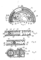
- the upper part of the shaft 8 is integral with a radial arm 12 which is perpendicular thereto and the end section 13 of which sweeps a trajectory in an arc 14, between two opposing compression springs 15 and 16. In the middle of this trajectory 14 are provided for the springs 15 and 16, stops 17 corresponding to the neutral position of the arm 12 and, consequently, of the adjustable fin 2. At this position (FIGS. 1 and 2), the fin 2 is oriented in the axis of the hull 3 which advances so in a straight line.
- each spring 15, 16 is supported in the housing 87 of an adjustable fixed carriage, referenced respectively 18, 19.
- Each of these carriages 18, 19 has a profile in an arc of a circle and, on its outer face closest to the central shaft 8, a rack teeth 20, 21.
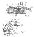
- Each of these teeth meshes on a pinion 22, 23 whose upper face has a diametrical groove 24 capable of receiving the end of an adjustment screwdriver 25 ( Figure 8).
- Each pinion 22, 23 is hollow and it covers a compression spring 26 which recalls it elastically upwards, against the housing 10 which is cut at this location through an opening 27 for the introduction of the screwdriver 25 at the time of the adjustments. Between two adjustments, each opening 27 is closed by a removable cover 28 ( Figure 7).
- a stop anchor 29, 30 is provided for each pinion 22, 23 in the teeth of which it meshes with its lugs 31.
- each anchor 29, 30 immobilizes in rotation the corresponding pinion 22, 23 when the latter is in the rest position under the thrust of its spring 26 ( Figure 7).
- the user presses with the screwdriver 25 to drive down a pinion such as 23 ( Figure 8) it lowers by a height 32 ( Figure 8) which is greater than the thickness 33 of the anchor 30.
- the toothing of the pinion 23 escapes from the stop lugs 31 of the anchor 30, but remains meshed with the toothing of the rack 21.
- the arm 12 preferably has a cross section in the form of an ace of diamonds ( Figures 3, 5 and 6). he rubs on the flexible teeth of two fixed linings in an arc 32 and 33 between which it moves. On the same lower lining 32, on either side of the neutral central position 34 defined by the stops 17, the teeth are inclined in opposite divergent positions. Thus, the flexible teeth 35 on the port side 36 are oriented upwards and to port, while the flexible teeth 37 on the starboard side 38 are oriented upwards and to starboard.
- the port teeth 39 are inclined downward and to port, while the starboard teeth 40 are inclined downward and to starboard. Finally these teeth 35, 37 and 39, 40 are staggered.
- the operation is as follows.
- the linings easily allow the movements of the arm 12 to develop in the direction which leads to deflecting the path of the board (case of arrow 82, FIG. 6), but they brake them more in the opposite direction (case of return, arrow 81, figure 5).
- the linings 32, 33 are preferably produced with a narrower width 83 in the central part close to the position 34.
- the user of the device according to the invention is particularly advantageous when the operator is sailing upwind.
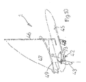
- FIG. 10 to 15 a windsurfing board 1 equipped with a device 42 according to the invention.
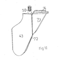
- This device 42 relates to a directional fin 43 whose orientation can be variable by rotation about a vertical theoretical axis 44.
- the windsurf board 1 comprises a float or hull 45, a mast 46 and a sail 47.
- the hull 45 is equipped in the known manner with a fin 48.
- the assembly is completed by an arch or whishbone 49 also known.
- the fin 43 is integral with a vertical shaft 50, the upper part of which rotates freely in the bearings 51. a fixed housing 52, integral with the shell 45. The seal is ensured by O-rings not shown.
- the upper part of the shaft 50 is secured to a radial arm 53 which is perpendicular thereto and the end section of which is fitted with two ferromagnetic parts, namely an upper part 54 and a lower part 55.
- the end of the arm 53 scans a trajectory in an arc of a circle (FIG. 14) between two adjustable fixed stops 56 and 57.
- Each of these two stops comprises a permanent magnet, so that the ferromagnetic cheeks 58, 59 of the end of the arm 53 remain there stuck at each end of the stroke of the arm 53 to the right or to the left.
- Each magnetic stop 56, 57 is integral with a slide 60.
- the latter receives the thrust of a longitudinal screw 61 which is articulated therein at 62.
- a rotary nut 63 On each screw 61 is screwed a rotary nut 63 whose external part comprises a pinion or a worm gear teeth 64.
- the latter meshes with a worm gear or on a gear 65 whose head 66 is accessible from outside the float 45.
- Each head 66 may have a diametrical groove 67 as in the case illustrated on fig. 13: one can then operate with a simple screwdriver, each of the two heads 66 whose rotation in one direction or the other makes it possible to adjust the longitudinal position of each of the two adjustable fixed magnetic stops 56 and 57.
- two permanent permanent magnets upper 67 and lower 68 are incorporated into the housing 52. These two magnets 67 and 68 face each other, on either side of the arm 53 which can pass between with a reduced air gap 69.
- the attraction magnetic is sufficient to immobilize the linings 54 and 55 of the arm 53 between the two magnets 67 and 68, the arm 53 and the fin 43 are immobilized in the central neutral position, that is to say at the position for which the windsurf 1 advance in a straight line.
- each adjustment head 66 is placed at the bottom of a well 70 of the housing 52, which well may possibly be closed by a removable plug 71.
- a small fixed fin 75 which orientation can also be adjusted once and for all from a head 74.
- the presence of this small fixed fin 75 is optional.
- the windsurfer pushes with the foot on the hull 45.
- the fin 43 tends to naturally take an orientation. In fact, it resists this tendency, under the effect of the temporary magnetic immobilization to which it is subjected. Indeed, its ferromagnetic end 58, 59, 54, 55 is normally immobilized: - Or against the magnetic stop 56; - Or against the magnetic stop 57; - or between the two magnets 67 and 68 in the neutral position.
- the magnetic immobilization force remains effective up to a given force threshold.
- the arm 53 deviates from the above-mentioned position and takes a new orientation: except in exceptional cases, this new orientation corresponds to its immobilization by one of the other magnets.
- the device according to the invention allows the fin 43 to occupy a fixed position, among three angular positions defined by the various magnets.
- the passage from one to the other of these three positions takes place automatically by magnetic tearing, as soon as the force resulting from navigation exceeds the setting threshold of the magnets.
Landscapes
- Chemical & Material Sciences (AREA)
- Engineering & Computer Science (AREA)
- Combustion & Propulsion (AREA)
- Mechanical Engineering (AREA)
- Ocean & Marine Engineering (AREA)
- Toys (AREA)
Applications Claiming Priority (4)
| Application Number | Priority Date | Filing Date | Title |
|---|---|---|---|
| FR8804973A FR2629786B1 (fr) | 1988-04-06 | 1988-04-06 | Dispositif a aileron orientable automatique, notamment pour une planche a voile ou analogue |
| FR8804973 | 1988-04-06 | ||
| FR8902375A FR2643328B1 (fr) | 1989-02-20 | 1989-02-20 | Dispositif automatique pour la commande de l'aileron orientable d'une planche a voile ou analogue |
| FR8902375 | 1989-02-20 |
Publications (1)
| Publication Number | Publication Date |
|---|---|
| EP0337904A1 true EP0337904A1 (de) | 1989-10-18 |
Family
ID=26226609
Family Applications (1)
| Application Number | Title | Priority Date | Filing Date |
|---|---|---|---|
| EP89420128A Withdrawn EP0337904A1 (de) | 1988-04-06 | 1989-04-05 | Vorrichtung mit selbstregelnder verstellbarer Flosse besonders für ein Segelbrett oder dergleichen |
Country Status (2)
| Country | Link |
|---|---|
| US (1) | US5070804A (de) |
| EP (1) | EP0337904A1 (de) |
Cited By (1)
| Publication number | Priority date | Publication date | Assignee | Title |
|---|---|---|---|---|
| US5195444A (en) * | 1991-08-29 | 1993-03-23 | Daniels John J | Sailboard |
Families Citing this family (6)
| Publication number | Priority date | Publication date | Assignee | Title |
|---|---|---|---|---|
| US5335616A (en) * | 1993-05-04 | 1994-08-09 | Tiesler Robin F | Boat rudder control system |
| US6213044B1 (en) | 2000-02-07 | 2001-04-10 | John M. Rodgers | Water craft with adjustable fin |
| US6439940B1 (en) * | 2001-04-24 | 2002-08-27 | Alexander Pouchkarev | Fin and watercraft system |
| US7001236B2 (en) * | 2003-12-23 | 2006-02-21 | Blake Jr David T | Dynamic fin system for watercraft |
| US7513456B2 (en) * | 2005-05-13 | 2009-04-07 | The Boeing Company | Apparatus and method for reduced backlash steering tiller |
| DE102019112970A1 (de) | 2019-05-16 | 2020-11-19 | Raoul Geburzky | Finnenkopplungsvorrichtung zum Befestigen einer Finne an einem Surfbrett |
Citations (2)
| Publication number | Priority date | Publication date | Assignee | Title |
|---|---|---|---|---|
| DE3123967A1 (de) * | 1981-06-19 | 1983-01-13 | Hans-Joachim 8500 Nürnberg Horn | "einmann-wasserfahrzeug zum segeln" |
| US4708675A (en) * | 1986-06-16 | 1987-11-24 | Shoeffler David M | Steerable surfing body board |
Family Cites Families (5)
| Publication number | Priority date | Publication date | Assignee | Title |
|---|---|---|---|---|
| US471202A (en) * | 1892-03-22 | victor | ||
| US491545A (en) * | 1893-02-14 | Jean marie anatole gerard | ||
| US653601A (en) * | 1900-05-03 | 1900-07-10 | Williamson Brothers Company | Tiller steering-gear for vessels. |
| US763701A (en) * | 1903-10-12 | 1904-06-28 | Elwood E Taylor | Steering apparatus. |
| US1593823A (en) * | 1922-09-21 | 1926-07-27 | Evinrude Motor Company | Tiller-positioning device |
-
1989
- 1989-04-05 EP EP89420128A patent/EP0337904A1/de not_active Withdrawn
- 1989-04-24 US US07/342,369 patent/US5070804A/en not_active Expired - Fee Related
Patent Citations (2)
| Publication number | Priority date | Publication date | Assignee | Title |
|---|---|---|---|---|
| DE3123967A1 (de) * | 1981-06-19 | 1983-01-13 | Hans-Joachim 8500 Nürnberg Horn | "einmann-wasserfahrzeug zum segeln" |
| US4708675A (en) * | 1986-06-16 | 1987-11-24 | Shoeffler David M | Steerable surfing body board |
Cited By (1)
| Publication number | Priority date | Publication date | Assignee | Title |
|---|---|---|---|---|
| US5195444A (en) * | 1991-08-29 | 1993-03-23 | Daniels John J | Sailboard |
Also Published As
| Publication number | Publication date |
|---|---|
| US5070804A (en) | 1991-12-10 |
Similar Documents
| Publication | Publication Date | Title |
|---|---|---|
| FR2532908A1 (fr) | Dispositif d'entrainement d'helices pour bateaux | |
| EP0994016B1 (de) | Bremsvorrichtung für Schneefahrzeug | |
| EP0337904A1 (de) | Vorrichtung mit selbstregelnder verstellbarer Flosse besonders für ein Segelbrett oder dergleichen | |
| FR2854864A1 (fr) | Embarcation nautique a voile | |
| FR2629786A1 (fr) | Dispositif a aileron orientable automatique, notamment pour une planche a voile ou analogue | |
| FR2643328A1 (fr) | Dispositif automatique pour la commande de l'aileron orientable d'une planche a voile ou analogue | |
| FR2481223A1 (fr) | Voilier trimaran muni d'un systeme de compensation de la gite | |
| FR2577194A1 (fr) | Greement permettant d'incliner lateralement le mat d'un bateau a voile | |
| FR2822798A1 (fr) | Greement de voilure pour une embarcation mue par le vent | |
| CH629106A5 (fr) | Fixation de securite pour ski. | |
| CH372565A (fr) | Glisseur nautique automobile | |
| FR2654063A1 (fr) | Dispositif automatique pour le positionnement de l'aileron orientable d'une planche a voile, ou analogue. | |
| EP0613815B1 (de) | Sportwasserfahrzeug | |
| FR2463051A1 (fr) | Ensemble compose d'une rame articulee et de son support | |
| FR3072076B3 (fr) | Glisseur sous-marin pour des bateaux transformables en un hydroglisseur a partir d'un stabilisateur d'assiette | |
| FR2598756A1 (fr) | Dispositif de derive ou analogue, agissant dans un fluide | |
| FR2725686A1 (fr) | Systeme anti-derive pour navire eolien | |
| CH591358A5 (en) | Light hydrofoil water craft - has front and rear skis and one piece hull and saddle | |
| FR2634294A1 (fr) | Dispositif de commande a position neutre reglable | |
| WO1998027336A1 (fr) | Dispositif generateur d'electricite a roue a aubes pour bateau ou analogue | |
| WO2024089335A1 (fr) | Système de traction auto-orientable pour bateau | |
| WO1994029168A1 (fr) | Greement comportant une voilure non supportee par un mat et hydroptere pourvu d'un tel greement | |
| FR2584993A1 (fr) | Ski nautique propulse par un moteur | |
| FR2932772A1 (fr) | Embarcation multicoques rotatives. | |
| BE447708A (de) |
Legal Events
| Date | Code | Title | Description |
|---|---|---|---|
| PUAI | Public reference made under article 153(3) epc to a published international application that has entered the european phase |
Free format text: ORIGINAL CODE: 0009012 |
|
| AK | Designated contracting states |
Kind code of ref document: A1 Designated state(s): DE GB IT NL SE |
|
| 17P | Request for examination filed |
Effective date: 19891219 |
|
| 17Q | First examination report despatched |
Effective date: 19910605 |
|
| STAA | Information on the status of an ep patent application or granted ep patent |
Free format text: STATUS: THE APPLICATION IS DEEMED TO BE WITHDRAWN |
|
| 18D | Application deemed to be withdrawn |
Effective date: 19911019 |