EP0337922B1 - Installation de chauffage - Google Patents
Installation de chauffage Download PDFInfo
- Publication number
- EP0337922B1 EP0337922B1 EP89710027A EP89710027A EP0337922B1 EP 0337922 B1 EP0337922 B1 EP 0337922B1 EP 89710027 A EP89710027 A EP 89710027A EP 89710027 A EP89710027 A EP 89710027A EP 0337922 B1 EP0337922 B1 EP 0337922B1
- Authority
- EP
- European Patent Office
- Prior art keywords
- temperature
- heat exchanger
- heating
- burner
- temperature sensor
- Prior art date
- Legal status (The legal status is an assumption and is not a legal conclusion. Google has not performed a legal analysis and makes no representation as to the accuracy of the status listed.)
- Expired - Lifetime
Links
Images

Classifications
-
- F—MECHANICAL ENGINEERING; LIGHTING; HEATING; WEAPONS; BLASTING
- F24—HEATING; RANGES; VENTILATING
- F24D—DOMESTIC- OR SPACE-HEATING SYSTEMS, e.g. CENTRAL HEATING SYSTEMS; DOMESTIC HOT-WATER SUPPLY SYSTEMS; ELEMENTS OR COMPONENTS THEREFOR
- F24D19/00—Details
- F24D19/10—Arrangement or mounting of control or safety devices
- F24D19/1006—Arrangement or mounting of control or safety devices for water heating systems
- F24D19/1066—Arrangement or mounting of control or safety devices for water heating systems for the combination of central heating and domestic hot water
- F24D19/1069—Arrangement or mounting of control or safety devices for water heating systems for the combination of central heating and domestic hot water regulation in function of the temperature of the domestic hot water
-
- F—MECHANICAL ENGINEERING; LIGHTING; HEATING; WEAPONS; BLASTING
- F24—HEATING; RANGES; VENTILATING
- F24H—FLUID HEATERS, e.g. WATER OR AIR HEATERS, HAVING HEAT-GENERATING MEANS, e.g. HEAT PUMPS, IN GENERAL
- F24H15/00—Control of fluid heaters
- F24H15/20—Control of fluid heaters characterised by control inputs
- F24H15/212—Temperature of the water
- F24H15/223—Temperature of the water in the water storage tank
-
- F—MECHANICAL ENGINEERING; LIGHTING; HEATING; WEAPONS; BLASTING
- F24—HEATING; RANGES; VENTILATING
- F24H—FLUID HEATERS, e.g. WATER OR AIR HEATERS, HAVING HEAT-GENERATING MEANS, e.g. HEAT PUMPS, IN GENERAL
- F24H15/00—Control of fluid heaters
- F24H15/30—Control of fluid heaters characterised by control outputs; characterised by the components to be controlled
- F24H15/305—Control of valves
Definitions
- the invention relates to a method for controlling a heating system with a primary heat exchanger that can be heated by a burner and to the flow of the primary heat exchanger via a three-way valve connected to the heating water circulation lines for heating a secondary heat exchanger arranged in a domestic hot water tank and at least one radiator, with a first temperature sensor in one for the secondary heat exchanger of the hot water tank leading branch of the flow line of the primary heat exchanger and a second temperature sensor are arranged in or on the hot water tank or its tap line and to control the three-way valve and a valve regulating the fuel supply to the burner, the two temperature sensors via signal lines to a common, via control lines with which the fuel supply to The burner regulating valve and the regulator connected to the three-way valve are connected.
- this process water temperature is also dependent on the respective draw-off quantity and on the temperature of the cold water flowing from the supply line to the storage tank.
- the object of the invention is therefore to provide a method in which there is a guarantee of a constant, arbitrarily selectable hot water temperature which is independent of the respective cold water temperature and the respective tap quantity, in particular when the system is operated by means of a single-stage burner.
- the object is achieved in that, in the case of hot water tapping or recharging, the output of the burner is regulated as a function of the temperature detected by the first temperature sensor and its deviation from a target value, this target value depending on the difference between a set hot water temperature and the temperature measured by the second temperature sensor.
- a preselectable outlet temperature of the domestic water at the tap can be guaranteed regardless of the temperature of the incoming cold water and regardless of the respective tap quantity.
- a flow switch can be arranged in its cold water supply line or in its tap line, which starts the burner regardless of the instantaneous temperature of the storage water. If the burner is equipped with a combustion air or exhaust gas blower, the blower is operated continuously from the first burner cycle until the end of the tap cycle in order to achieve a delay-free cycle of the burner and thus to limit the fluctuations in the flow temperature to a minimum.
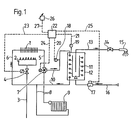
- the water heating system comprises a burner that heats a water-carrying heat exchanger 1, preferably a gas burner 2 Fuel gas is supplied via a gas supply line 3 and a valve 4 regulating the gas supply.
- This primary heat exchanger 1 emits heating water via a supply line 5 and is connected to a return line 6, which returns the cooled heating water.
- a three-way valve 7 is arranged, which either opens the way to a heating circuit 8 in which there is at least one heating element 9, or - during the continuous or recharging operation - the flow flowing from the primary heat exchanger the way to a secondary heat exchanger 11 of a hot water tank 12 via the circulation line 10 opens.
- a tap line 13 with at least one tap valve 14 and a tap point 15 starts from the hot water tank 12.
- the hot water tank 12 is supplied with cold water from the supply line 16.
- the flow switch 17 can be arranged, which is connected to the controller 22 via a signal line 25 and starts the continuous operation of the domestic hot water tank 12 as soon as a tap is taken.
- the system comprises at least two temperature sensors, namely a temperature sensor 18 in the flow line 10 of the heating water heating the hot water tank 12 and a temperature sensor 19 arranged in or on this hot water tank 12 itself or on the tap line 13.
- temperature sensors 18 and 19 are connected via signal lines 20 and 21 to a common controller 22 which controls the valve 4 regulating the fuel supply to the burner 2 via the control line 23 and the three-way valve 7 via the control line 24, depending on the two of them measured values transmitted by the temperature sensors 18 and 19.
- the controller 22 is assigned a preselection device 26 for the desired hot water temperature and connected to it via a control line 27.
- Figure 2 shows the head area of the domestic hot water tank 12 on a larger scale, together with the connection of the hot water circulating line 10 and the outlet of the tap line 13 and with part of the coil forming the secondary heat exchanger 11.
- the output of the burner 2 is regulated as a function of the temperature detected by the temperature sensor 18 in the flow line 10 and its deviation from a predetermined target value.
- This target value is formed by the controller 22 as a function of the difference between the hot water temperature set on the preselection device 26 and the temperature measured on the sensor 19.
- the target value for the flow temperature is reduced, thus ensuring a hot water temperature that is independent of the cold water temperature and the flow rate (draw-off volume).
- this temperature sensor 19 also takes over the function of a mechanical thermostat that regulates the temperature of the storage water and starts or ends a recharging of the domestic water storage.
Landscapes
- Engineering & Computer Science (AREA)
- General Engineering & Computer Science (AREA)
- Thermal Sciences (AREA)
- Combustion & Propulsion (AREA)
- Mechanical Engineering (AREA)
- Physics & Mathematics (AREA)
- Chemical & Material Sciences (AREA)
- Steam Or Hot-Water Central Heating Systems (AREA)
- Sorption Type Refrigeration Machines (AREA)
- General Induction Heating (AREA)
- General Preparation And Processing Of Foods (AREA)
- Domestic Hot-Water Supply Systems And Details Of Heating Systems (AREA)
- Air-Conditioning For Vehicles (AREA)
- Investigating Or Analyzing Materials By The Use Of Fluid Adsorption Or Reactions (AREA)
- Display Devices Of Pinball Game Machines (AREA)
Claims (1)
- Procédé pour la régulation d'une installation de chauffage comprenant un échangeur de chaleur primaire (1) chauffé par un brûleur (2), et une tuyauterie d'eau chaude (10 et 8) branchée sur le raccord de sortie (5) de l'échangeur de chaleur primaire (1) par l'intermédiaire d'un distributeur 3-voies (7), et destinée à alimenter un échangeur de chaleur secondaire (11) logé dans un accumulateur d'eau sanitaire (12), et au moins un radiateur de chauffage (9), une première sonde thermométrique (18) étant prévue dans une branche du tuyau de départ (5) de l'échangeur de chaleur primaire (1), qui se termine à l'échangeur de chaleur secondaire (11) de l'accumulateur d'eau (12), et une deuxième sonde thermométrique (19), dans ou sur l'accumulateur d'eau sanitaire (12) ou le tuyau de prise d'eau (13) branché sur lui, sondes thermométriques (18 et 19) reliées par des lignes de signalisation (20 et 21) à un régulateur commun (22) agissant par l'intermédiaire de lignes de commande (23 et 24) sur le distributeur 3-voies (7) et la valve (4) réglant l'alimentation du brûleur (2) en combustible, caractérisé par le fait que lors du prélèvement ou du réchauffement de l'eau sanitaire, la puissance fournie par le brûleur (2) est réglée en fonction de la température relevée par la première sonde thermométrique (18) et de l'écart entre cette température et une consigne préréglée qui, elle, est formée en fonction de la différence entre la température d'eau sanitaire voulue et la température mesurée par la deuxième sonde thermométrique (19).
Applications Claiming Priority (2)
| Application Number | Priority Date | Filing Date | Title |
|---|---|---|---|
| AT0097888A AT389584B (de) | 1988-04-15 | 1988-04-15 | Heizungsanlage |
| AT978/88 | 1988-04-15 |
Publications (3)
| Publication Number | Publication Date |
|---|---|
| EP0337922A2 EP0337922A2 (fr) | 1989-10-18 |
| EP0337922A3 EP0337922A3 (en) | 1990-10-31 |
| EP0337922B1 true EP0337922B1 (fr) | 1994-02-02 |
Family
ID=3504143
Family Applications (1)
| Application Number | Title | Priority Date | Filing Date |
|---|---|---|---|
| EP89710027A Expired - Lifetime EP0337922B1 (fr) | 1988-04-15 | 1989-04-17 | Installation de chauffage |
Country Status (3)
| Country | Link |
|---|---|
| EP (1) | EP0337922B1 (fr) |
| AT (2) | AT389584B (fr) |
| DE (2) | DE58906857D1 (fr) |
Families Citing this family (8)
| Publication number | Priority date | Publication date | Assignee | Title |
|---|---|---|---|---|
| BE1004890A6 (nl) * | 1990-05-07 | 1993-02-16 | Vaillant Sa | Waterverhittingsinrichting. |
| IT1254266B (it) * | 1992-03-12 | 1995-09-14 | Gruppo idraulico perfezionato per impianti misti di riscaldamento e acqua sanitaria | |
| AT402764B (de) * | 1992-04-07 | 1997-08-25 | Vaillant Gmbh | Wasserheizer für brauch- und heizungswasser |
| AT405465B (de) * | 1996-01-15 | 1999-08-25 | Vaillant Gmbh | Wasserheizungsanlage |
| SE9601181D0 (sv) * | 1996-03-27 | 1996-03-27 | Alf Ottosson | Sätt och anordning för temperaturreglering av tappvarmvatten |
| DE19850714A1 (de) * | 1998-11-03 | 2000-05-04 | Gaswaerme Inst Ev | Verfahren und Anordnung zur Heizwärme- und Warmwasserbereitung |
| DE102009034556A1 (de) * | 2009-07-23 | 2011-02-03 | Viessmann Werke Gmbh & Co Kg | Verfahren zur Überwachung des Verschmutzungszustandes eines Wärmetauschers zur Warmwasserbereitung an einem Heizgerät |
| IT201600068864A1 (it) * | 2016-07-01 | 2018-01-01 | Eti S N C Di Fogale Maria Elisa & Bortolato Luciano | Kit o sistema di distribuzione di energia termica per la produzione di acqua calda sanitaria e per riscaldamento e impianto utilizzante detto kit |
Family Cites Families (4)
| Publication number | Priority date | Publication date | Assignee | Title |
|---|---|---|---|---|
| AT306305B (de) * | 1970-12-14 | 1973-04-10 | Vaillant Joh Kg | Umlaufheizungsanlage mit Gebrauchswasserbereiter |
| DE2142545B1 (fr) * | 1971-08-25 | 1973-02-08 | Joh. Vaillant Kg, 5630 Remscheid | |
| DE2307109A1 (de) * | 1973-02-14 | 1974-08-29 | Junkers & Co | Heizgeraet fuer brauch- und heizwasser |
| GB2151816B (en) * | 1983-12-19 | 1986-10-08 | British Gas Corp | Control of a central heating system |
-
1988
- 1988-04-15 AT AT0097888A patent/AT389584B/de not_active IP Right Cessation
-
1989
- 1989-04-17 EP EP89710027A patent/EP0337922B1/fr not_active Expired - Lifetime
- 1989-04-17 AT AT89710027T patent/ATE101255T1/de not_active IP Right Cessation
- 1989-04-17 DE DE89710027T patent/DE58906857D1/de not_active Expired - Fee Related
- 1989-04-17 DE DE3912593A patent/DE3912593A1/de not_active Withdrawn
Also Published As
| Publication number | Publication date |
|---|---|
| ATA97888A (de) | 1989-05-15 |
| DE58906857D1 (de) | 1994-03-17 |
| EP0337922A2 (fr) | 1989-10-18 |
| EP0337922A3 (en) | 1990-10-31 |
| AT389584B (de) | 1989-12-27 |
| ATE101255T1 (de) | 1994-02-15 |
| DE3912593A1 (de) | 1989-10-26 |
Similar Documents
| Publication | Publication Date | Title |
|---|---|---|
| EP0308848B1 (fr) | Méthode et dispositif pour la régulation de la température d'un medium de chauffage d'un système de chauffage à circuit tenué avec limitation de la température minimale | |
| DE69709928T2 (de) | Kombiniertes Regelsystem für Gas und Luft zur Verbrennungsregelung eines Gasheizkessels | |
| AT394771B (de) | Verfahren und einrichtung zur durchfuehrung des verfahrens zum sofortigen zapfen von warmem brauchwasser | |
| EP0892223B1 (fr) | Dispositif de commande et de régulation pour système de chauffage | |
| EP0337922A2 (fr) | Installation de chauffage | |
| EP1310746B1 (fr) | Dispositif et procédé de regulation d'un chauffe-eau | |
| DE4303579A1 (en) | Fuel fired heater for hot water heating system - has monitor for mean temperature of heat exchanger to allow for condensation effects | |
| DE19530000A1 (de) | Warmwasserbereitungsanlage | |
| EP0229319B1 (fr) | Installation de chauffage à eau chaude avec calorimètre | |
| DE2931024C2 (de) | Vorrichtung zur Steuerung der Brennstoffzufuhr und der Luftzufuhr zu einem Brenner | |
| EP0642069B1 (fr) | Dispositif de régulation | |
| CH688491A5 (de) | Verfahren zum Betrieb eines einen Brenner aufweisenden Brennwertgeraetes. | |
| EP1508751A1 (fr) | Procédé et dispositif pour adapter la temperature de départ d'un générateur de chaleur à la charge respective du circuit de chauffage d'une installation de chauffage connectée en aval | |
| DE102005040792B3 (de) | Selbstlernender Temperaturregler | |
| EP0049328A1 (fr) | Dispositif de récupération de chaleur des gaz d'échappement de plusieurs installations | |
| DE19511366B4 (de) | Verfahren zur Steuerung einer Heizungsanlage | |
| DE3832495A1 (de) | Verfahren und vorrichtung zur steuerung der temperatur des heizmediums einer umlaufheizung mit einer minimaltemperaturbegrenzung | |
| AT397854B (de) | Verfahren zur steuerung eines kessels | |
| DE2529858A1 (de) | Verfahren und vorrichtung zur steuerung einer waermeuebertragungsanlage, insbesondere zentralheizungsanlage | |
| DE3515658C2 (fr) | ||
| DE3503738A1 (de) | Schaltung zum steuern der waermeabgabe einer brennstoffbeheizten waermequelle | |
| DE19645135A1 (de) | Verfahren zur Steuerung einer Heizungsanlage | |
| DE4110629C1 (en) | Heat or cooling generator regulator - has by=pass line between outward and return paths each with own temp. sensor | |
| DE3871701T2 (de) | Gaskesselregulierungseinrichtung. | |
| EP0916903A2 (fr) | Installation de chauffage de locaux et procédé pour son opération |
Legal Events
| Date | Code | Title | Description |
|---|---|---|---|
| PUAI | Public reference made under article 153(3) epc to a published international application that has entered the european phase |
Free format text: ORIGINAL CODE: 0009012 |
|
| AK | Designated contracting states |
Kind code of ref document: A2 Designated state(s): AT BE CH DE ES FR GB GR IT LI LU NL SE |
|
| PUAL | Search report despatched |
Free format text: ORIGINAL CODE: 0009013 |
|
| AK | Designated contracting states |
Kind code of ref document: A3 Designated state(s): AT BE CH DE ES FR GB GR IT LI LU NL SE |
|
| 17P | Request for examination filed |
Effective date: 19901212 |
|
| 17Q | First examination report despatched |
Effective date: 19910814 |
|
| RAP1 | Party data changed (applicant data changed or rights of an application transferred) |
Owner name: VAILLANT S.A.R.L Owner name: VAILLANT GES.M.B.H Owner name: VAILLANT B.V. Owner name: VAILLANT GMBH Owner name: VAILLANT LTD. Owner name: JOH. VAILLANT GMBH U. CO. Owner name: N.V. VAILLANT S.A. |
|
| RAP3 | Party data changed (applicant data changed or rights of an application transferred) |
Owner name: N.V. VAILLANT S.A. Owner name: JOH. VAILLANT GMBH U. CO. Owner name: VAILLANT GMBH Owner name: VAILLANT S.A.R.L Owner name: VAILLANT GES.M.B.H Owner name: VAILLANT B.V. Owner name: VAILLANT LTD. |
|
| GRAA | (expected) grant |
Free format text: ORIGINAL CODE: 0009210 |
|
| AK | Designated contracting states |
Kind code of ref document: B1 Designated state(s): AT BE CH DE ES FR GB GR IT LI LU NL SE |
|
| PG25 | Lapsed in a contracting state [announced via postgrant information from national office to epo] |
Ref country code: IT Free format text: LAPSE BECAUSE OF FAILURE TO SUBMIT A TRANSLATION OF THE DESCRIPTION OR TO PAY THE FEE WITHIN THE PRE;WARNING: LAPSES OF ITALIAN PATENTS WITH EFFECTIVE DATE BEFORE 2007 MAY HAVE OCCURRED AT ANY TIME BEFORE 2007. THE CORRECT EFFECTIVE DATE MAY BE DIFFERENT FROM THE ONE RECORDED.SCRIBED TIME-LIMIT Effective date: 19940202 Ref country code: GB Effective date: 19940202 Ref country code: GR Free format text: LAPSE BECAUSE OF FAILURE TO SUBMIT A TRANSLATION OF THE DESCRIPTION OR TO PAY THE FEE WITHIN THE PRESCRIBED TIME-LIMIT Effective date: 19940202 Ref country code: ES Free format text: THE PATENT HAS BEEN ANNULLED BY A DECISION OF A NATIONAL AUTHORITY Effective date: 19940202 Ref country code: SE Effective date: 19940202 Ref country code: NL Effective date: 19940202 |
|
| REF | Corresponds to: |
Ref document number: 101255 Country of ref document: AT Date of ref document: 19940215 Kind code of ref document: T |
|
| REF | Corresponds to: |
Ref document number: 58906857 Country of ref document: DE Date of ref document: 19940317 |
|
| PG25 | Lapsed in a contracting state [announced via postgrant information from national office to epo] |
Ref country code: LU Free format text: LAPSE BECAUSE OF NON-PAYMENT OF DUE FEES Effective date: 19940430 |
|
| ET | Fr: translation filed | ||
| NLV1 | Nl: lapsed or annulled due to failure to fulfill the requirements of art. 29p and 29m of the patents act | ||
| GBV | Gb: ep patent (uk) treated as always having been void in accordance with gb section 77(7)/1977 [no translation filed] |
Effective date: 19940202 |
|
| PLBE | No opposition filed within time limit |
Free format text: ORIGINAL CODE: 0009261 |
|
| STAA | Information on the status of an ep patent application or granted ep patent |
Free format text: STATUS: NO OPPOSITION FILED WITHIN TIME LIMIT |
|
| 26N | No opposition filed | ||
| PGFP | Annual fee paid to national office [announced via postgrant information from national office to epo] |
Ref country code: BE Payment date: 19950308 Year of fee payment: 7 |
|
| PGFP | Annual fee paid to national office [announced via postgrant information from national office to epo] |
Ref country code: FR Payment date: 19950322 Year of fee payment: 7 |
|
| PGFP | Annual fee paid to national office [announced via postgrant information from national office to epo] |
Ref country code: AT Payment date: 19950323 Year of fee payment: 7 |
|
| PGFP | Annual fee paid to national office [announced via postgrant information from national office to epo] |
Ref country code: CH Payment date: 19950327 Year of fee payment: 7 |
|
| PG25 | Lapsed in a contracting state [announced via postgrant information from national office to epo] |
Ref country code: AT Effective date: 19960417 |
|
| PG25 | Lapsed in a contracting state [announced via postgrant information from national office to epo] |
Ref country code: CH Effective date: 19960430 Ref country code: LI Effective date: 19960430 Ref country code: BE Effective date: 19960430 |
|
| PGFP | Annual fee paid to national office [announced via postgrant information from national office to epo] |
Ref country code: DE Payment date: 19960430 Year of fee payment: 8 |
|
| BERE | Be: lapsed |
Owner name: N.V. VAILLANT S.A. Effective date: 19960430 |
|
| REG | Reference to a national code |
Ref country code: CH Ref legal event code: PL |
|
| PG25 | Lapsed in a contracting state [announced via postgrant information from national office to epo] |
Ref country code: FR Effective date: 19961227 |
|
| REG | Reference to a national code |
Ref country code: FR Ref legal event code: ST |
|
| PG25 | Lapsed in a contracting state [announced via postgrant information from national office to epo] |
Ref country code: DE Free format text: LAPSE BECAUSE OF NON-PAYMENT OF DUE FEES Effective date: 19980101 |