EP0337923A2 - Wasserheizer - Google Patents
Wasserheizer Download PDFInfo
- Publication number
- EP0337923A2 EP0337923A2 EP89710028A EP89710028A EP0337923A2 EP 0337923 A2 EP0337923 A2 EP 0337923A2 EP 89710028 A EP89710028 A EP 89710028A EP 89710028 A EP89710028 A EP 89710028A EP 0337923 A2 EP0337923 A2 EP 0337923A2
- Authority
- EP
- European Patent Office
- Prior art keywords
- burner
- water heater
- heat exchanger
- strands
- pipe
- Prior art date
- Legal status (The legal status is an assumption and is not a legal conclusion. Google has not performed a legal analysis and makes no representation as to the accuracy of the status listed.)
- Granted
Links
Images

Classifications
-
- F—MECHANICAL ENGINEERING; LIGHTING; HEATING; WEAPONS; BLASTING
- F28—HEAT EXCHANGE IN GENERAL
- F28F—DETAILS OF HEAT-EXCHANGE AND HEAT-TRANSFER APPARATUS, OF GENERAL APPLICATION
- F28F1/00—Tubular elements; Assemblies of tubular elements
- F28F1/10—Tubular elements and assemblies thereof with means for increasing heat-transfer area, e.g. with fins, with projections, with recesses
- F28F1/12—Tubular elements and assemblies thereof with means for increasing heat-transfer area, e.g. with fins, with projections, with recesses the means being only outside the tubular element
- F28F1/24—Tubular elements and assemblies thereof with means for increasing heat-transfer area, e.g. with fins, with projections, with recesses the means being only outside the tubular element and extending transversely
-
- F—MECHANICAL ENGINEERING; LIGHTING; HEATING; WEAPONS; BLASTING
- F24—HEATING; RANGES; VENTILATING
- F24H—FLUID HEATERS, e.g. WATER OR AIR HEATERS, HAVING HEAT-GENERATING MEANS, e.g. HEAT PUMPS, IN GENERAL
- F24H1/00—Water heaters, e.g. boilers, continuous-flow heaters or water-storage heaters
- F24H1/22—Water heaters other than continuous-flow or water-storage heaters, e.g. water heaters for central heating
- F24H1/40—Water heaters other than continuous-flow or water-storage heaters, e.g. water heaters for central heating with water tube or tubes
-
- F—MECHANICAL ENGINEERING; LIGHTING; HEATING; WEAPONS; BLASTING
- F24—HEATING; RANGES; VENTILATING
- F24H—FLUID HEATERS, e.g. WATER OR AIR HEATERS, HAVING HEAT-GENERATING MEANS, e.g. HEAT PUMPS, IN GENERAL
- F24H9/00—Details
- F24H9/0005—Details for water heaters
- F24H9/001—Guiding means
- F24H9/0026—Guiding means in combustion gas channels
-
- F—MECHANICAL ENGINEERING; LIGHTING; HEATING; WEAPONS; BLASTING
- F28—HEAT EXCHANGE IN GENERAL
- F28F—DETAILS OF HEAT-EXCHANGE AND HEAT-TRANSFER APPARATUS, OF GENERAL APPLICATION
- F28F2215/00—Fins
- F28F2215/04—Assemblies of fins having different features, e.g. with different fin densities
Definitions
- the invention relates to a water heater with a surface burner assigned to a combustion chamber, preferably a lint burner, and at least one heat exchanger arranged in the exhaust gas duct of this combustion chamber.
- Such water heaters are state of the art. Particularly in the case of water heaters with fan-operated surface burners and when using metallic or ceramic burner plates, the proportion of radiation energy in the overall output of the burner is comparatively large.
- the low visible flame height of such burners opens up the possibility of dimensioning and designing the combustion chamber in a very compact and space-saving manner.
- the design depends on the ratio of the burner area to that area of the heat exchange elements which is flown by the exhaust gases. It would be desirable to dimension the inflow area approximately the same size as the burner area.
- the object of the invention is therefore to reduce the thermal load on the elements closer to the burner.
- this object is achieved in that regions of the heat exchanger, for example pipe strands, which are closer to the burner in the exhaust gas duct are designed and / or arranged with a lower heat absorption capacity than heat exchanger regions which are further away from the burner.
- the heat exchange elements closer to the burner can consist of pipe strands, preferably steel pipe strands, with a smooth surface, while the heat exchange elements further away from the burner, for example pipe strings, on the other hand have a heat exchange surface which is enlarged by profiles, for example ribs. But you can also profile the pipe strings closer to the burner with ribs that have a smaller height or thickness than the ribs of pipe strings further away from the burner.
- pipe strings of the heat exchanger preferably steel pipe strands, which are closer to the burner have a smooth surface.
- a heat exchanger is known from AT-PS 378 422, which has a single-layer coil which is covered with fins in the area of the heat exchanger. Areas lying outside the heat exchanger are formed from smooth tube.
- the features of claim 2 ensure that the area closer to the burner is designed as a smooth tube without further processing, while the further area of the tube receives fins.
- tubular strings of the heat exchanger which are further away from the burner have a heat exchange surface which is enlarged by profiling, for example ribs, in a manner known per se.
- the tube strings that are closer to the burner are profiled with ribs that have a small height or thickness than the ribs that tube strings that are further away from the burner.
- these radiant heat absorbing elements are provided between a family of pipe strands with a smooth surface and a family of pipe strings with a heat exchange surface enlarged by profiling, for example ribs.
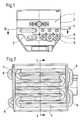
- the water heater shown in FIGS. 1 and 2 operated with a lint burner 1 and a fan, has a combustion chamber 2 and an exhaust gas duct 3, in which heat exchange elements are arranged; in all the exemplary embodiments, these heat exchange elements are designed as tubular strings of water-carrying coils.
- Ceramic rods 7 are located between these tube strings 4 and 6.
- These rods 7 are uncooled guide elements which serve to improve the exhaust gas flow and thus the heat reduction and to reduce the CO content of the exhaust gases.
- These heated rods 7 reach a surface temperature of about 800 to 900 ° C and in this way, as a heat accumulator, prevent the exhaust gases from cooling down too much within the water-cooled combustion chamber 2. This improves the burnout in the flow direction of the exhaust gases.
- the tube strings 4 are advantageously arranged congruently with the tube strands 6, in order thereby to keep part of the radiant heat of the burner 1 from the foremost group of the tube strands 6.
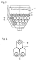
- FIG. 3 shows an embodiment variant in which the heat exchange elements closer to the burner 1 consist of tubes 8, the ribs 9 of which have a lower height than the ribs 11 of the tubes 10 further away from the burner. This also achieves the effect sought by the invention.
- FIG. 5 shows an embodiment variant in which the ceramic rams 7 are arranged directly in front of the group of pipe strands 8 closer to the burner 1.
Landscapes
- Engineering & Computer Science (AREA)
- Physics & Mathematics (AREA)
- General Engineering & Computer Science (AREA)
- Thermal Sciences (AREA)
- Mechanical Engineering (AREA)
- Chemical & Material Sciences (AREA)
- Combustion & Propulsion (AREA)
- Geometry (AREA)
- Gas Burners (AREA)
- Cookers (AREA)
- Resistance Heating (AREA)
- Thermally Insulated Containers For Foods (AREA)
- Instantaneous Water Boilers, Portable Hot-Water Supply Apparatuses, And Control Of Portable Hot-Water Supply Apparatuses (AREA)
- Heat-Pump Type And Storage Water Heaters (AREA)
Abstract
Description
- Die Erfindung bezieht sich auf einen Wasserheizer mit einem einer Brennkammer zugeordneten Flächenbrenner, vorzugsweise einem Sturzbrenner, und zumindest einem in der Abgasführung dieser Brennkammer angeordneten Wärmetauscher.
- Solche Wasserheizer sind allgemeiner Stand der Technik. Insbesondere bei Wasserheizer mit gebläsebetriebenen Flächenbrennern und bei Verwendung metallischer beziehungsweise keramischer Brennerplatten ist der Anteil der Strahlungsenergie an der Gesamtleistung des Brenners vergleichsweise groß.
- Die geringe sichtbare Flammenhöhe solcher Brenner erschließt die Möglichkeit, die Brennkammer sehr kompakt und raumsparend zu bemessen und zu gestalten.
- Die Gestaltung ist jedoch vom Verhältnis der Brennerfläche zu jener Fläche der Wärmetauschelemente abhängig, die von den Abgasen angeströmt wird. Wünschenswert wäre es, die Anströmfläche etwa gleich groß der Brennerfläche zu bemessen.
- Die aus diesem Grund relativ gleichmäßige Dichte des Wärmestromes führt jedoch bei Wärmetauschelementen mit vergleichsweise hoher Wärmetausch- und Wärmeaufnahmefähigkeit, zum Beispiel Rippenrohren, zu einer thermischen Überbelastung, insbesondere dann, wenn die spezifische Oberfläche solcher Elemente mehr als 0,4 m²/m beträgt.
- Aufgabe der Erfindung ist es deshalb, die thermische Belastung der dem Brenner näherliegenden Elemente zu reduzieren.
- Erfindungsgemäß wird diese Aufgabe dadurch gelöst, daß dem Brenner in der Abgasführung näherliegende Bereiche des Wärmetauschers, zum Beispiel Rohrstränge, mit einer geringeren Wärmeaufnahmefähigkeit ausgebildet und/oder angeordnet sind als dem Brenner fernerliegende Warmetauscherbereiche.
- Diese Bedingung läßt sich im Rahmen der Erfindung auf mannigfache Weise einhalten beziehungsweise verwirklichen.
- So können beispielsweise die dem Brenner näherliegenden Wärmetauschelemente aus Rohrsträngen, vorzugsweise Stahlrohrsträngen, mit glatter Oberfläche bestehen, die dem Brenner fernerliegenden Wärmetauschelemente, zum Beispiel Rohrstränge, hingegen eine durch Profilierungen, zum Beispiel Rippen, vergrößerte Wärmetauschfläche aufweisen. Man kann aber auch die dem Brenner näherliegenden Rohrstränge mit Rippen profilieren, die eine geringere Höhe beziehungsweise Dicke aufweisen als die Rippen dem Brenner fernerliegender Rohrstränge.
- In Ausgestaltung der Erfindung wird vorgeschlagen, daß dem Brenner näherliegende Rohrstränge des Wärmetauschers, vorzugsweise Stahlrohrstränge, eine glatte Oberfläche aufweisen.
- Aus der AT-PS 378 422 ist ein Wärmetauscher bekannt, der eine einlagige Rohrschlange aufweist, die im Bereich des Wärmetauschers mit Lamellen besetzt ist. Lediglich außerhalb des Wärmetauschers liegende Bereiche sind aus Glattrohr gebildet.
- Durch die Merkmale des Anspruchs 2 wird erreicht, daß ohne weiteren Bearbeitungsaufwand der dem Brenner näherliegende Bereich als Glattrohr ausgebildet wird, während der fernerliegende Bereich des Rohres Lamellen erhält.
- In weiterer Ausgestaltung der Erfindung wird vorgeschlagen, daß dem Brenner fernerliegende Rohrstränge des Wärmetauschers in an sich bekannter Weise eine durch Profilierungen, zum Beispiel Rippen, vergrößerte Wärmetauschlfläche aufweisen.
- Durch die bereits eben angeführte AT-PS und die DE-OS 3 413 712 ist es bekannt, Wärmetauscherrohre mit Profilierungen, zum Beispiel Rippen, zu versehen.
- Schlieblich ist es besonders zweckmäßig, daß die dem Brenner näherliegenden Rohrstränge mit Rippen profiliert sind, die eine geringe Höhe beziehungsweise Dicke aufweisen als die Rippen, die dem Brenner fernerliegender Rohrstränge.
- Aus der GB-PS 1 556 709 ist es bekannt, bei einem einlagigen Wärmetauscher die Lamellen so auszubilden, daß sie auf der dem Brenner zugewandten Seite eine geringere Höhe aufweisen als auf der dem Brenner abgewandten Seite.
- Durch die Anwendung der eben geschilderten Maßnahme bei einem mehrlagigen Wärmetauscher, bei dem es einen dem Brenner näherliegenden Bereich und eine dem Brenner fernerliegenden Bereich des Wärmetauschers gibt, ergibt sich eine besonders einfache Ausgestaltung des Haupterfindungsgedankens.
- Weiterhin ist es besonders zweckmäßig, daß in dem dem Brenner zugewandten Bereich der Rohrstränge des Wärmetauschers aus keramischen Material bestehende, Strahlungswärme aufnehmende Elemente, zum Beispiel Stäbe, parallel zu den Rohrsträngen verlaufend angeordnet sind. Durch diese Ausgestaltung kann auf die Stickoxydbildung des Brenners entscheidend Einfluß genommen werden.
- Schlußendlich ist es besonders zweckmäßig, daß diese Strahlungswärme aufnehmenden Elemente zwischen einer Schar von Rohrsträngen mit glatter Oberfläche und einer Schar von Rohrsträngen mit durch Profilierung, zum Beispiel Rippen, vergrößerten Wärmetauschfläche vorgesehen sind. Durch das Einbringen der die Strahlungswärme aufnehmenden Elemente zwischen einem Glattrohrstrang und einem Rippenrohrstrang läßt sich das Aufnehmen der Strahlungswärme besonders leicht bewerkstelligen.
- Im einzelnen zeigen:
- Figur 1 den Querschnitt eines Wasserheizers nach einer ersten Ausführungsform nach I-I der Figur 2 und
- Figur 2 einen Waagschnitt nach II-II der Figure 1.
- Figur 3 zeigt eine abgewandelte Ausführungsform eines solchen Wasserheizers gleichfalls in einem Querschnitt und
- Figur 4 stellt in einem Teilquerschnitt eine weitere Variante dar.
- Figur 5 zeigt den Querschnitt einer weiteren, abgewandelten Ausführungsform.
- Der in den Figuren 1 und 2 dargestellte, mit einem Sturzbrenner 1 und einem Gebläse betriebene Wasserheizer besitzt eine Brennkammer 2 und eine Abgasführung 3, in der Wärmetauschelemente angeordnet sind; diese Wärmetauschelemente sind bei allen Ausführungsbeispielen als Rohrstränge wasserführender Rohrschlangen ausgebildet.
- Innerhalb der Abgasführung 3 verlaufen zunächst - dem Brenner 1 näher - die Rohrstränge 4 einer aus Edelstahl bestehenden, an der Außenseite ihrer Wandung glatten Rohrschlange, die dann in der nächst unteren Ebene in eine aus den Rohrsträngen 6 bestehende Rohrschlange übergeht, die mit Rippen 5 bestückt ist.
- Zwischen diesen Rohrsträngen 4 und 6 befinden sich keramische Stäbe 7.
- Bei diesen Stäben 7 handelt es sich um ungekühlte Leitelemente, die zur Verbesserung der Abgasströmung und damit der Wärmereduktion sowie zur Verringerung des CO-Gehaltes der Abgase dienen. Diese aufgeheizten Stäbe 7 erreichen eine Oberflächentemperatur von etwa 800 bis 900 °C und verhindern auf diese Weise als Wärmespeicher eine zu starke Abkühlung der Abgase innerhalb der wassergekühlten Brennkammer 2. Dadurch wird der Ausbrand in der Strömungsrichtung der Abgase verbessert.
- Wie Figur 1 erkennen läßt, werden die Rohrstränge 4 vorteilhaft deckungsgleich mit den Rohrsträngen 6 angeordnet, um dadurch einen Teil der Strahlungswärme des Brenners 1 von der vordersten Schar der Rohrstränge 6 abzuhalten.
- Figur 3 zeigt eine Ausführungsvariante, bei der die dem Brenner 1 näherliegenden Wärmetauschelemente aus Rohren 8 bestehen, deren Rippen 9 eine geringere Höhe aufweisen als die Rippen 11 der dem Brenner fernerliegenden Rohre 10. Auch dadurch wird der von der Erfindung angestrebte Effekt erzielt.
- Ebenso kann dieser Effekt dadurch erzielt werden, daß - nach Figur 4 - die Rippen 11 der die Wärmetauschelemente bildenden Rohrstränge 10 an ihrer dem Brenner 1 zugewendeten Seite kürzer ausgebildet sind als an der dem Brenner 1 abgewandten Seite.
- Figur 5 zeigt eine Ausführungsvariante, bei der die keramischen Stäße 7 unmittelbar vor der dem Brenner 1 näherliegenden Schar der Rohrstränge 8 angeordnet sind.
Claims (7)
Applications Claiming Priority (2)
| Application Number | Priority Date | Filing Date | Title |
|---|---|---|---|
| AT977/88 | 1988-04-15 | ||
| AT0097788A AT395268B (de) | 1988-04-15 | 1988-04-15 | Wasserheizer |
Publications (3)
| Publication Number | Publication Date |
|---|---|
| EP0337923A2 true EP0337923A2 (de) | 1989-10-18 |
| EP0337923A3 EP0337923A3 (en) | 1990-10-31 |
| EP0337923B1 EP0337923B1 (de) | 1992-11-11 |
Family
ID=3504123
Family Applications (1)
| Application Number | Title | Priority Date | Filing Date |
|---|---|---|---|
| EP89710028A Expired - Lifetime EP0337923B1 (de) | 1988-04-15 | 1989-04-17 | Wasserheizer |
Country Status (5)
| Country | Link |
|---|---|
| EP (1) | EP0337923B1 (de) |
| AT (2) | AT395268B (de) |
| DE (2) | DE58902642D1 (de) |
| ES (1) | ES2037460T3 (de) |
| GR (1) | GR3006755T3 (de) |
Cited By (3)
| Publication number | Priority date | Publication date | Assignee | Title |
|---|---|---|---|---|
| GB2286237A (en) * | 1994-01-14 | 1995-08-09 | Hallam Edmond | Finned tube heat exchanger for gas fired boilers. |
| EP0687870A1 (de) * | 1994-06-15 | 1995-12-20 | Atag Verwarming B.V. | Wärmetauscher |
| US6763786B2 (en) * | 2001-10-24 | 2004-07-20 | Outokumpu Oyj | Equipment for water heater |
Families Citing this family (5)
| Publication number | Priority date | Publication date | Assignee | Title |
|---|---|---|---|---|
| DE4404596A1 (de) * | 1994-02-12 | 1995-08-17 | Interdomo Gmbh & Co | Wärmetauscher mit beschichteten Rohren |
| DE4410716A1 (de) * | 1994-02-12 | 1995-08-17 | Interdomo Gmbh & Co | Wärmetauscher mit lamellenfreier erster Rohrreihe |
| DE4406030C2 (de) * | 1994-02-24 | 1997-12-18 | Buderus Heiztechnik Gmbh | Brennwertkessel |
| DE19529559A1 (de) * | 1995-08-11 | 1997-02-13 | Wieland Werke Ag | Wärmeaustauschsystem zur Wassererwärmung |
| DE19723727A1 (de) * | 1997-05-31 | 1998-12-03 | Vaillant Joh Gmbh & Co | Lamellenwärmetauscher |
Family Cites Families (8)
| Publication number | Priority date | Publication date | Assignee | Title |
|---|---|---|---|---|
| AT250409B (de) * | 1962-05-17 | 1966-11-10 | Waagner Biro Ag | Wärmetauscher, insbesondere für druckgefeuerte Dampfkessel |
| NL6912511A (de) * | 1969-08-17 | 1971-02-19 | ||
| DE7528615U (de) * | 1975-09-10 | 1976-03-04 | Robert Bosch Gmbh, 7000 Stuttgart | Wassererhitzer mit einem atmosphaerischen brenner fuer gasfoermige oder fluessige brennstoffe |
| DE2742839A1 (de) * | 1977-09-23 | 1979-04-05 | Bosch Gmbh Robert | Waermeuebertrager fuer einen gas- oder oelbeheizten durchlauf-wassererhitzer |
| DE2742854C2 (de) * | 1977-09-23 | 1985-05-02 | Robert Bosch Gmbh, 7000 Stuttgart | Wassererhitzer mit einem Gas- oder Ölbrenner |
| FR2524971A1 (fr) * | 1982-04-08 | 1983-10-14 | Deleage Philippe | Generateur de chauffe modulaire |
| FR2530320B1 (de) * | 1982-07-19 | 1984-12-21 | Fives Cail Babcock | |
| DE3413712A1 (de) * | 1984-04-12 | 1985-10-17 | Wen Chuan Fengshan City Taiwan Yuan | Waermetauscherrohr und verfahren zu seiner herstellung |
-
1988
- 1988-04-15 AT AT0097788A patent/AT395268B/de not_active IP Right Cessation
-
1989
- 1989-04-17 EP EP89710028A patent/EP0337923B1/de not_active Expired - Lifetime
- 1989-04-17 AT AT89710028T patent/ATE82381T1/de active
- 1989-04-17 ES ES198989710028T patent/ES2037460T3/es not_active Expired - Lifetime
- 1989-04-17 DE DE8989710028T patent/DE58902642D1/de not_active Expired - Lifetime
- 1989-04-17 DE DE3912616A patent/DE3912616A1/de not_active Withdrawn
-
1993
- 1993-01-08 GR GR920403160T patent/GR3006755T3/el unknown
Cited By (4)
| Publication number | Priority date | Publication date | Assignee | Title |
|---|---|---|---|---|
| GB2286237A (en) * | 1994-01-14 | 1995-08-09 | Hallam Edmond | Finned tube heat exchanger for gas fired boilers. |
| GB2286237B (en) * | 1994-01-14 | 1998-04-08 | Hallam Edmond | Heat exchanger |
| EP0687870A1 (de) * | 1994-06-15 | 1995-12-20 | Atag Verwarming B.V. | Wärmetauscher |
| US6763786B2 (en) * | 2001-10-24 | 2004-07-20 | Outokumpu Oyj | Equipment for water heater |
Also Published As
| Publication number | Publication date |
|---|---|
| DE3912616A1 (de) | 1989-10-26 |
| ATA97788A (de) | 1992-03-15 |
| ES2037460T3 (es) | 1993-06-16 |
| DE58902642D1 (de) | 1992-12-17 |
| AT395268B (de) | 1992-11-10 |
| EP0337923A3 (en) | 1990-10-31 |
| ATE82381T1 (de) | 1992-11-15 |
| EP0337923B1 (de) | 1992-11-11 |
| GR3006755T3 (de) | 1993-06-30 |
Similar Documents
| Publication | Publication Date | Title |
|---|---|---|
| DE2552679C3 (de) | Wärmeübertragungsrohr | |
| EP0349834B1 (de) | Durchlaufdampferzeuger | |
| DE2552102A1 (de) | Sonnenkessel | |
| DE3317162C2 (de) | Kessel für flüssige oder gasförmige Brennstoffe zur Warmwasser-, Heißwasser- oder Dampferzeugung | |
| EP0337923A2 (de) | Wasserheizer | |
| EP0778932A1 (de) | Durchlaufdampferzeuger | |
| CH630168A5 (de) | Durchlauf-wassererhitzer. | |
| DE19529559A1 (de) | Wärmeaustauschsystem zur Wassererwärmung | |
| DE19602680A1 (de) | Durchlaufdampferzeuger | |
| EP0225929A1 (de) | Gasbeheizte Kesselanlage und Verwendung davon | |
| EP0767888B1 (de) | Vorrichtung zum erwärmen von brauchwasser | |
| DE9404888U1 (de) | Sonnenkollektor | |
| DE3231211C2 (de) | Einrichtung für eine Brennkammer mit einem Öl- oder Gasbrenner | |
| DE3815751C2 (de) | Sonnenkollektor | |
| CH644441A5 (de) | Sonnenkollektor. | |
| DE2709301A1 (de) | Waermeaustauschvorrichtung zum einfangen von strahlungsenergie | |
| DE2918306C2 (de) | Wärmetauscher für einen Heizkamin | |
| DE1751641A1 (de) | Zwangdurchlaufdampferzeuger mit aus vertikalen verschweissten Rohren gebildeter Wandberohrung und Verfahren zum Betrieb des Dampferzeugers | |
| AT396981B (de) | Lamellenwärmetauscher | |
| DE19842486C2 (de) | Brennelement mit qualifizierter Verteilung von spaltbarem Material im Brennstab | |
| DE9109424U1 (de) | Lamellenblock-Wärmetauscher | |
| DE9105410U1 (de) | Zentralheizungskessel | |
| DE1751641C (de) | Zwangdurchlaufdampferzeuger mit aus vertikalen verschweissten Rohren gebildeter Wandberohrung | |
| DE2149840C3 (de) | Warmwasser-Heizkessel für eine Sammelheizungsanlage | |
| DE9017483U1 (de) | Lamellenblock |
Legal Events
| Date | Code | Title | Description |
|---|---|---|---|
| PUAI | Public reference made under article 153(3) epc to a published international application that has entered the european phase |
Free format text: ORIGINAL CODE: 0009012 |
|
| AK | Designated contracting states |
Kind code of ref document: A2 Designated state(s): AT BE CH DE ES FR GB GR IT LI LU NL SE |
|
| PUAL | Search report despatched |
Free format text: ORIGINAL CODE: 0009013 |
|
| AK | Designated contracting states |
Kind code of ref document: A3 Designated state(s): AT BE CH DE ES FR GB GR IT LI LU NL SE |
|
| RHK1 | Main classification (correction) |
Ipc: F24H 1/40 |
|
| 17P | Request for examination filed |
Effective date: 19901212 |
|
| 17Q | First examination report despatched |
Effective date: 19910214 |
|
| RAP1 | Party data changed (applicant data changed or rights of an application transferred) |
Owner name: VAILLANT GMBH Owner name: VAILLANT-SCHONEWELLE B.V. Owner name: VAILLANT LTD. Owner name: VAILLANT GES.M.B.H Owner name: VAILLANT S.A.R.L Owner name: N.V. VAILLANT S.A. Owner name: JOH. VAILLANT GMBH U. CO. |
|
| GRAA | (expected) grant |
Free format text: ORIGINAL CODE: 0009210 |
|
| AK | Designated contracting states |
Kind code of ref document: B1 Designated state(s): AT BE CH DE ES FR GB GR IT LI LU NL SE |
|
| REF | Corresponds to: |
Ref document number: 82381 Country of ref document: AT Date of ref document: 19921115 Kind code of ref document: T |
|
| REF | Corresponds to: |
Ref document number: 58902642 Country of ref document: DE Date of ref document: 19921217 |
|
| GBT | Gb: translation of ep patent filed (gb section 77(6)(a)/1977) |
Effective date: 19921201 |
|
| ITF | It: translation for a ep patent filed | ||
| PGFP | Annual fee paid to national office [announced via postgrant information from national office to epo] |
Ref country code: GR Payment date: 19930303 Year of fee payment: 5 |
|
| PGFP | Annual fee paid to national office [announced via postgrant information from national office to epo] |
Ref country code: BE Payment date: 19930310 Year of fee payment: 5 |
|
| PGFP | Annual fee paid to national office [announced via postgrant information from national office to epo] |
Ref country code: LU Payment date: 19930315 Year of fee payment: 5 Ref country code: ES Payment date: 19930315 Year of fee payment: 5 |
|
| PGFP | Annual fee paid to national office [announced via postgrant information from national office to epo] |
Ref country code: SE Payment date: 19930316 Year of fee payment: 5 |
|
| ET | Fr: translation filed | ||
| EPTA | Lu: last paid annual fee | ||
| REG | Reference to a national code |
Ref country code: GR Ref legal event code: FG4A Free format text: 3006755 |
|
| REG | Reference to a national code |
Ref country code: ES Ref legal event code: FG2A Ref document number: 2037460 Country of ref document: ES Kind code of ref document: T3 |
|
| PLBE | No opposition filed within time limit |
Free format text: ORIGINAL CODE: 0009261 |
|
| STAA | Information on the status of an ep patent application or granted ep patent |
Free format text: STATUS: NO OPPOSITION FILED WITHIN TIME LIMIT |
|
| 26N | No opposition filed | ||
| PGFP | Annual fee paid to national office [announced via postgrant information from national office to epo] |
Ref country code: GB Payment date: 19940316 Year of fee payment: 6 |
|
| PGFP | Annual fee paid to national office [announced via postgrant information from national office to epo] |
Ref country code: FR Payment date: 19940329 Year of fee payment: 6 |
|
| PG25 | Lapsed in a contracting state [announced via postgrant information from national office to epo] |
Ref country code: LU Free format text: LAPSE BECAUSE OF NON-PAYMENT OF DUE FEES Effective date: 19940417 |
|
| PG25 | Lapsed in a contracting state [announced via postgrant information from national office to epo] |
Ref country code: SE Effective date: 19940418 Ref country code: ES Free format text: LAPSE BECAUSE OF NON-PAYMENT OF DUE FEES Effective date: 19940418 |
|
| PG25 | Lapsed in a contracting state [announced via postgrant information from national office to epo] |
Ref country code: BE Effective date: 19940430 |
|
| BERE | Be: lapsed |
Owner name: S.A. VAILLANT N.V. Effective date: 19940430 |
|
| PG25 | Lapsed in a contracting state [announced via postgrant information from national office to epo] |
Ref country code: GR Free format text: THE PATENT HAS BEEN ANNULLED BY A DECISION OF A NATIONAL AUTHORITY Effective date: 19941031 |
|
| EUG | Se: european patent has lapsed |
Ref document number: 89710028.5 Effective date: 19941110 |
|
| REG | Reference to a national code |
Ref country code: GR Ref legal event code: MM2A Free format text: 3006755 |
|
| PGFP | Annual fee paid to national office [announced via postgrant information from national office to epo] |
Ref country code: CH Payment date: 19950327 Year of fee payment: 7 |
|
| PGFP | Annual fee paid to national office [announced via postgrant information from national office to epo] |
Ref country code: DE Payment date: 19950328 Year of fee payment: 7 |
|
| PG25 | Lapsed in a contracting state [announced via postgrant information from national office to epo] |
Ref country code: GB Effective date: 19950417 |
|
| GBPC | Gb: european patent ceased through non-payment of renewal fee |
Effective date: 19950417 |
|
| PG25 | Lapsed in a contracting state [announced via postgrant information from national office to epo] |
Ref country code: FR Effective date: 19951229 |
|
| REG | Reference to a national code |
Ref country code: FR Ref legal event code: ST |
|
| PG25 | Lapsed in a contracting state [announced via postgrant information from national office to epo] |
Ref country code: LI Effective date: 19960430 Ref country code: CH Effective date: 19960430 |
|
| REG | Reference to a national code |
Ref country code: CH Ref legal event code: PL |
|
| PG25 | Lapsed in a contracting state [announced via postgrant information from national office to epo] |
Ref country code: DE Effective date: 19970101 |
|
| PGFP | Annual fee paid to national office [announced via postgrant information from national office to epo] |
Ref country code: NL Payment date: 19980312 Year of fee payment: 10 Ref country code: AT Payment date: 19980312 Year of fee payment: 10 |
|
| PG25 | Lapsed in a contracting state [announced via postgrant information from national office to epo] |
Ref country code: AT Free format text: LAPSE BECAUSE OF NON-PAYMENT OF DUE FEES Effective date: 19990417 |
|
| REG | Reference to a national code |
Ref country code: ES Ref legal event code: FD2A Effective date: 19990503 |
|
| PG25 | Lapsed in a contracting state [announced via postgrant information from national office to epo] |
Ref country code: NL Free format text: LAPSE BECAUSE OF NON-PAYMENT OF DUE FEES Effective date: 19991101 |
|
| NLV4 | Nl: lapsed or anulled due to non-payment of the annual fee |
Effective date: 19991101 |
|
| PG25 | Lapsed in a contracting state [announced via postgrant information from national office to epo] |
Ref country code: IT Free format text: LAPSE BECAUSE OF NON-PAYMENT OF DUE FEES Effective date: 20050417 |