EP0337975A2 - Dispositif de ventilation - Google Patents
Dispositif de ventilation Download PDFInfo
- Publication number
- EP0337975A2 EP0337975A2 EP89870036A EP89870036A EP0337975A2 EP 0337975 A2 EP0337975 A2 EP 0337975A2 EP 89870036 A EP89870036 A EP 89870036A EP 89870036 A EP89870036 A EP 89870036A EP 0337975 A2 EP0337975 A2 EP 0337975A2
- Authority
- EP
- European Patent Office
- Prior art keywords
- profile
- sound
- absorbing
- rotary
- coupling elements
- Prior art date
- Legal status (The legal status is an assumption and is not a legal conclusion. Google has not performed a legal analysis and makes no representation as to the accuracy of the status listed.)
- Granted
Links
Images

Classifications
-
- F—MECHANICAL ENGINEERING; LIGHTING; HEATING; WEAPONS; BLASTING
- F24—HEATING; RANGES; VENTILATING
- F24F—AIR-CONDITIONING; AIR-HUMIDIFICATION; VENTILATION; USE OF AIR CURRENTS FOR SCREENING
- F24F13/00—Details common to, or for air-conditioning, air-humidification, ventilation or use of air currents for screening
- F24F13/24—Means for preventing or suppressing noise
-
- F—MECHANICAL ENGINEERING; LIGHTING; HEATING; WEAPONS; BLASTING
- F24—HEATING; RANGES; VENTILATING
- F24F—AIR-CONDITIONING; AIR-HUMIDIFICATION; VENTILATION; USE OF AIR CURRENTS FOR SCREENING
- F24F13/00—Details common to, or for air-conditioning, air-humidification, ventilation or use of air currents for screening
- F24F13/08—Air-flow control members, e.g. louvres, grilles, flaps or guide plates
- F24F13/18—Air-flow control members, e.g. louvres, grilles, flaps or guide plates specially adapted for insertion in flat panels, e.g. in door or window-pane
-
- F—MECHANICAL ENGINEERING; LIGHTING; HEATING; WEAPONS; BLASTING
- F24—HEATING; RANGES; VENTILATING
- F24F—AIR-CONDITIONING; AIR-HUMIDIFICATION; VENTILATION; USE OF AIR CURRENTS FOR SCREENING
- F24F7/00—Ventilation
- F24F2007/0025—Ventilation using vent ports in a wall
Definitions
- This invention relates to a rotary sound-absorbing ventilation grid, more particularly to a rotary sound-absorbing ventilation grid, the ventilation mouth of which can be closed or can be entirely or respectively partially opened so that the noise usually produced can be muffled from the most efficiently thanks to the insertion of such a ventilation grid.
- This invention relates to a rotary sound-absorbing ventilation grid in which the ventilation grid per se consists mainly of a drum fitted with diametrically opposite longitudinal grooves and in which the vertical placement in superposition, respectively the horizontal placement in consecutiveness, of these grooves has for effect that a junction is made or not between the two sides of the ventilation grille.
- the present invention relates more particularly to soundproofing of these rotary ventilation grilles which ensures that the noise, originating from the outside, is as much as possible muffled and that it does not penetrate or that it does not introduce itself or weakly in the space equipped with such a ventilation grille.
- This sound absorbing ventilation grid mainly consists of a rotary ventilation grid known per se and of a soundproofing box which is provided on one side of the grid, where this box consists of profiles which, in cooperation with the component profiles the grid, retain one or more layers of soundproofing material at a determined distance from one another in order to form a channel between these layers of soundproofing material which forms a connection between the rotary ventilation grid and the atmosphere.
- FIG. 1 represents a window, a door or other construction 1 which is designed to receive a sound-absorbing ventilation grid 2 according to the invention in such a way that the complete sound-absorbing ventilation grid is located inside the space in which it is installed.
- This rotary sound-absorbing ventilation grid consists mainly of two parts according to the invention, that is to say the rotary ventilation grid 3 per se and the sound-absorbing part or the sound-absorbing housing 4.
- the rotary ventilation grille 3 consists in this embodiment mainly of two sections, respectively 5 and 6 which are fixed reciprocally in a known manner not shown by end plates and where these sections 5 and 6 each have two spaces, respectively 7, 8 and 9, 10, for fixing a brush 11 where two shells, respectively 12 and 13, cooperate which are also mutually connected at their ends and which can be turned relative to the sections 5 and 6 in order to realize that the slots 14 and 15 formed between the shells 12 and 13 establish a connection, either in their entirety or partially, between one and the other side of the ventilation grille, or to hermetically seal these sides between them.
- the grid is equipped on the one hand with a projection 17 on the profile 5 and on the other hand with a hook-shaped protuberance 18 below the profile 6.
- the sound absorbing housing 4 according to the invention is designed in such a way that it cannot only be widened or raised, but that it can be, seen in section, installed in determined locations relative to the window with which it must cooperate, i.e. it can be placed more or less inwards or outwards in the construction where it is installed, always taking into account the installation of an appropriate thermal interruption .
- the soundproofing box is mainly formed by an upper part 19 and a lower part 20 which are connected, not shown, but suitably by their ends, as is the case for the rotary ventilation grid. 3, by end plates.
- the upper part 19 is formed by a first external profile 21, a corner profile 22, an intermediate profile 23 and a terminal profile 24.
- the angle profile 21 consists in this case of a downwardly hanging part 25 which, so to speak, prevents water from entering the housing, where the profile has two protuberances, respectively 26 and 27, for the support of a layer of sound-absorbing material 28, on the one hand, and a hook-shaped end 29 and a distance support 30, on the other hand, which form the coupling elements, so to speak.
- the corner profile 22 has a free end 31 which can cooperate with the hook-shaped end 29 of the angle profile 21 and a tongue 32 placed around it, the free end of which rests against the support 30 of the angle profile 21, placed on this end 29
- These parts 31, 32 form coupling elements which can cooperate with the coupling elements 29, 30.
- the second upright of the corner profile 22 has a hook-shaped element 29 at its end and a protuberance 30 as it was the case for the profile 21. Between them the profile 22 has wings, respectively 33 and 34, the free ends of which have parts, respectively 35 and 36, which are parallel with the external surface of the profile 22 and which serve as a shoulder for the layer of soundproofing material 28.
- a layer of thermal insulation material 37 is provided between the wings 33 and 34 which, in known manner, can be obtained by pouring such a material into the profile 22 and then cutting out a part 38 of it. profiled in order to obtain a thermal interruption.
- the profile 23 is formed at one end by the above elements 29 and 30 and at the other end by the above elements 31 and 32. Likewise, the wings 33, 34 and the parts 35, 36 are provided in such a way that material 37 can be poured into it and forms a possible interruption 38.
- section 24 consists in an identical manner to the previous of the parts 30 to 36 while a curved part 39 is provided at one of the ends with which the protuberance 17 of the rotary ventilation grid 3 can cooperate.
- the upper part 19 is completed by a profile 40 whose arms 41 and 42 serve as shoulders for a layer of soundproofing material 28 and where this profile also fits into the profile 5 of the grid 3.
- the lower part 20 of the housing 4 is mainly produced by a section 24 mentioned above and an almost double section 23 which is indicated in this case by 43.
- this profile 43 does not only present the elements of the profile 23, but also a pair of intermediate wings 33, 34 with protrusions 35, 36.
- an angle profile 44 is provided which presents the elements 29 and 30 mentioned above and which is curved towards the inside of the housing 4 so as to preferably have a protuberance 45 placed at 45 degrees which in this case has four spaces 46 above which are each limited by a shaped edge 45 mushroom and where in these adjustment spaces 46, respectively between two mushroom-shaped edges 47, an inverted mushroom-shaped edge 48 of an adjustment profile 49 can be installed which has a curved portion 50 in order to position the layer sound absorbing absorbent 51, with the protrusions 35, 36 of the sections 24 and 43, on the one hand, and the section 6 of the rotary ventilation grid 3, on the other.
- a rotary sound-absorbing ventilation grid is obtained, that is to say a rotary ventilation grid 3 which is produced with a sound-absorbing housing 4 and where this sound-absorbing housing, in a simple manner, instead of a window, of a door or the like 1, is fitted with a thermal break 37.
- the rotary ventilation grille 3 may be, as indicated schematically by a dotted line in FIG. 1, hooked in a simple manner by means of the hook-shaped end 18 of the profile 6 behind a hook-shaped end 39 of a profile 24 so as to then be pivoted upwards and to be fixed by one or more screws not shown to the construction of the housing 4.
- This embodiment also makes it possible to be appropriately widened by the insertion of one or more elements 19, both at the top and at the bottom, while the adjustment of the air flow 52 is possible by the displacement of the profile 49 by relative to the section 44 as shown by a dashed line in FIG. 1.
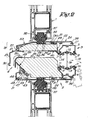
- FIG. 2 represents an embodiment where the rotary ventilation grid is formed in a perfectly identical manner as described above and where the sections 21, 24, 43, 44, 49, 40 and 44 are used for the soundproofing box, where the only difference between the previous one resides in that the angle profile 21 cooperates in this case with a profile 53 which is formed identically to that described above but which is equipped with an inclined part.
- thermal break 37 is located practically in the center of the housing 4, the whole so that this housing is placed for half outside and half inside construction 1.
- a sound-absorbing ventilation grille is obtained in this way which can be produced in different heights and widths, in which the same series of constituent profiles is practically always applied and in which, according to several locations the desired construction, a cryogenic bridge can be provided, on the one hand, and where the air passage 52 can be reduced or increased in order to influence the ventilation flow, on the one hand, and the passage of noise, d 'somewhere else.
Landscapes
- Engineering & Computer Science (AREA)
- Chemical & Material Sciences (AREA)
- Combustion & Propulsion (AREA)
- Mechanical Engineering (AREA)
- General Engineering & Computer Science (AREA)
- Specific Sealing Or Ventilating Devices For Doors And Windows (AREA)
- Duct Arrangements (AREA)
- Air-Flow Control Members (AREA)
Abstract
Description
- Cette invention a trait à une grille rotative de ventilation insonorisante, plus particulièrement une grille rotative de ventilation insonorisante dont la bouche de ventilation peut être obturée ou peut entièrement, respectivement partiellement, être ouverte de telle façon que le bruit produit habituellement puisse être étouffé de la manière la plus efficace grâce à l'insertion d'une telle grille de ventilation.
- Cette invention a trait à une grille rotative de ventilation insonorisante dans laquelle la grille de ventilation en soi consiste principalement en un tambour équipé de rainures longitudinales diamètralement opposées et dans lequel le placement vertical en superposition, respectivement le placement horizontal en consécution, de ces rainures a pour effet qu'une jonction se fait ou non entre les deux côtés de la grille de ventilation.
- Etant donné que ces grilles de ventilation, dans la position ouverte, donc en général lorsque les rainures susdites se situent l'une derrière l'autre, forment pour ainsi dire une connexion directe entre le local dont elles forment une partie intégrale et l'atmosphère il est tout aussi évident que les bruits da la rue ou similaires reçoivent une entrée directe vers le local susdit.
- En effet, le seul élément qui, généralement, est installé dans ces passages, est un treillis qui est généralement incorporé dans une telle de ventilation pour empêcher l'intrusion d'insectes, de poussière ou similaires.
- La présente invention a plus particulièrement trait à une insonorisation de ces grilles rotatives de ventilation qui assure que le bruit, originaire de l'extérieur, soit le plus possible étouffé et qu'il ne pénètre pas ou qu'il ne s'introduit pas ou faiblement dans l'espace équipé d'une telle grille de ventilation.
- Cette grille de ventilation insonorisante consiste principalement en une grille rotative de ventilation connue en soi et d'un boîtier d'insonorisation qui est prévu d'un côté de la grille, où ce boîtier consiste en des profilés qui, en coopération avec les profilés composant la grille, retiennent une ou plusieurs couches de matière insonorisante a une distance déterminée l'une de l'autre afin de former un canal entre ces couches de matière insonorisante qui forme und liaison entre la grille rotative de ventilation et l'atmosphère.
- Dans le but de mieux démontrer les caractéristiques de l'invention, des formes préférentielles d'une telle grille de ventilation insonorisante sont décrites ci-après comme exemple sans caractère restrictif avec des références aux dessins ci-inclus dans lesquels :
- figure 1 représente une coupe verticale d'une réalisation qui est équipée d'une grille de ventilation insonorisante suivant l'invention ;
- figures 2, 3 et 4 représentent des variantes de réalisations représentées dans la figure 1.
- La figure 1 représente une fenêtre, une porte ou autre construction 1 qui est prévue pour recevoir une grille de ventilation insonorisante 2 suivant l'invention de telle façon que la grille de ventilation insonorisante complète est située à l'intérieur de l'espace dans laquelle elle est installée.
- Cette grille rotative de ventilation insonorisante consiste principalement suivant l'invention de deux parties, c'est-à-dire la grille rotative de ventilation 3 en soi et la partie insonorisante ou le boîtier insonorisant 4.
- La grille rotative de ventilation 3 consiste dans cette réalisation principalement de deux profilés, respectivement 5 et 6 qui sont fixés de façon réciproque de manière connue non représentée par des plaques terminales et où ces profilés 5 et 6 comportent chacun deux espaces, respectivement 7, 8 et 9, 10, pour la fixation d'une brosse 11 où deux coquilles, respectivement 12 et 13, coopèrent qui sont aussi mutuellement reliées à leurs extrémités et qui peuvent être tournées par rapport aux profilés 5 et 6 afin de réaliser que les fentes 14 et 15 formées entre les coquilles 12 et 13 établissent une liaison, soit dans leur totalité, soit partiellement, entre l'un et l'autre côté de la grille de ventilation, soit d'obturer hermétiquement ces côtés entr'eux.
- Dans cette grille rotative de ventilation il est connu qu'elle est équipée d'un treillis 16 qu empêche le passage des insectes, de la poussière ou similaire.
- Une telle rotative de ventilation est connue en soi.
- Dans ce cas-ci la grille est équipée d'une part d'une saillie 17 sur le profilé 5 et d'autre part d'une protubérance en forme de crochet 18 au dessous du profilé 6.
- Le boîtier insonorisant 4 suivant l'invention est réalisé de telle façon qu'il ne peut pas seulement être élargi ou surélevé, mais qu'il peut être, vu en coupe, installé dans des endroits déterminés par rapport à la fenêtre avec laquelle il doit coopérer, c'est-à-dire qu'il peut être plus ou moins placé vers l'intérieur ou vers l'extérieur dans la construction où il est installé et ceci en tenant toujours compte de l'installation d'une interruption thermique appropriée.
- Suivant la présente invention le boîtier insonorisant est principalement formé par une partie supérieure 19 et une partie inférieure 20 qui sont reliées, de façon non représentée, mais de manière appropriée par leurs extrémités, tel qu'il est le cas pour la grille rotative de ventilation 3, par des plaques terminales.
- Dans la réalisation suivant la figure 1 la partie supérieure 19 est formée par un premier profilé extérieur 21, un profilé d'angle 22, un profilé intermédiaire 23 et un profilé terminal 24.
- Le profil d'angle 21 consiste dans ce cas d'une partie pendante vers le bas 25 qui pour ainsi dire empêche l'eau de s'introduire dans le boîtier, où profilé présente deux protubérances, respectivement 26 et 27, pour le soutien d'une couche de matière insonorisante 28, d'une part, et une extrémité en forme de crochet 29 et un support de distance 30, d'autre part, qui forment pour ainsi dire les éléments d'accouplement.
- Le profilé d'angle 22 présente une extrémité libre 31 qui peut coopérer avec l'extrémité en forme de crochet 29 du profilé d'angle 21 et une languette 32 placée autour de celui-ci, dont l'extrémité libre repose contre le support 30 du profilé d'angle 21, placée sur cette extrémité 29. Ces parties 31, 32 forment des éléments d'acouplement qui peuvent coopérer avec les éléments d'accouplement 29, 30.
- Grâce à cette coopération on obtient que les profilés 21 et 22 sont positionnés de manière appropriée, l'un par rapport à l'autre.
- Le deuxième montant du profilé d'angle 22 présente un élément en forme de crochet 29 à son extrémité et une protubérance 30 tel qu'il était le cas pour le profilé 21. Entre ceux-ci le profilé 22 présente des ailes, respectivement 33 et 34 dont les extrémités libres présentent des parties, respectivement 35 et 36, qui sont parallèles avec la surface extérieure du profilé 22 et qui servent d'épaulement pour la couche de matière insonorisante 28.
- Dans ce cas une couche de matière d'isolation thermique 37 est prévue entre les ailes 33 et 34 qui, de façon connue, peut être obtenue par le versage d'une telle matière dans le profilé 22 et de découper ensuite une partie 38 de ce profilé afin d'obtenir une interruption thermique.
- Le profilé 23 est formé à une extrémité par les éléments 29 et 30 susdit et à l'autre extrémité par les éléments 31 et 32 susdits. De même, les ailes 33, 34 et les parties 35, 36 sont prévues de telle manière à ce que de la matière 37 peut y être versée et forme une interruption 38 éventuelle.
- Enfin, le profilé 24 consiste de manière identique à la précédente des parties 30 à 36 tandis qu'une partie courbée 39 est prévue à une des extrémités avec laquelle la protubérance 17 de la grille rotative de ventilation 3 peut coopérer.
- Enfin, la partie supérieure 19 est complétée par une profilé 40 dont les bras 41 et 42 servent d'épaulement pour une couche de matériel insonorisant 28 et où ce profilé s'emboîte également dans la profilé 5 de la grille 3.
- La partie inférieure 20 du boîtier 4 est principalement réalisée par un profilé 24 précité et un profilé quasiment double 23 qui est indiqué dans ce cas par 43.
- En effet, ce profilé 43 ne présente pas seulement les éléments du profilé 23, mais aussi une paire d'ailes 33, 34 intermédiaires avec des protubérances 35, 36. A l'avant un profilé d'angle 44 est prévu qui présente les éléments 29 et 30 précités et qui est courbé vers l'intérieur du boîtier 4 afin de présenter de préférence une protubérance 45 placée à 45 degrés qui présente, dans ce cas quatre, espaces 46 au-dessus qui sont chacun limités par une arête 45 en forme de champignon et où dans ces espaces de réglage 46, respectivement entre deux arêtes 47 en forme de champignon, une arête en forme de champignon inversée 48 d'un profilé de réglage 49 peut être installé qui présente une partie courbée 50 afin de positionner la couche insonorisante absorbante 51, avec les protubérances 35, 36 des profilés 24 et 43, d'une part, et le profilé 6 de la grille rotative de ventilation 3, d'autre part.
- De cette manière on obtient une grille rotative de ventilation insonorisante, c'est-à-dire une grille rotative de ventilation 3 qui est réalisée avec un boîtier insonorisant 4 et où ce boîtier insonorisant, de manière simple, au lieu d'une fenêtre, d'une porte ou similaire 1, est équipé d'une interruption thermique 37.
- La grille rotative de ventilation 3 pourra être, tel qu'indiqué schématiquement par une ligne en pointillés dans la figure 1, accrochée de manière simple par l'entremise de l'extrémité en forme de crochet 18 du profilé 6 derrière une extrémité en forme de crochet 39 d'un profilé 24 afin d'être pivotée ensuite vers le haut et d'être fixée par une ou plusieurs vis non représentées à la construction du boîtier 4.
- Il est évident que, grâce au pivotage vers le bas de la grille rotative de ventilation 3, les plaques en matière insonorisante 28 et 51 sont facilement accessibles afin qu'elles puissent être retirées pour nettoyage et/ou remplacement.
- Cette réalisation permet également d'être élargie de façon appropriée par l'insertion d'un ou plusieurs éléments 19, tant en haut qu'en bas, tandis que le réglage de débit d'air 52 est possible par le déplacement du profilé 49 par rapport au profilé 44 tel que représenté par un trait mixte dans la figure 1.
- La figure 2 représente une réalisation où la grille rotative de ventilation est formée de manière parfaitement identique tel que décrit précédemment et où les profilés 21, 24, 43, 44, 49, 40 et 44 sont utilisés pour le boîtier insonorisant, où la seule différence entre la précédente réside en ce que le profilé d'angle 21 coopère dans ce cas avec un profilé 53 qui est formé de façon identique à celle décrite ci-dessus mais qui est équipé d'une partie inclinée.
- Dans les dessins il apparaît dans cette réalisation que l'interruption thermique 37 se trouve pratiquement au centre du boîtier 4, le tout de manière à ce que ce boîtier est placé pour le moitié à l'extérieur et pour la moitié à l'intérieur de la construction 1.
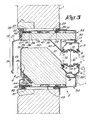
- Dans la figure 3 une réalisation est représenteé dans laquelle les mêmes éléments on été appliqués tel que décrit ci-dessus, mais avec l'exception que des profilés 54 sont appliqués à l'intérieur qui présentent une hauteur plus élevée, le tout de manière à ce que la hauteur totale du boîtier insonorisant 4 et donc que les couches insonorisantes, plus particulièrement la couche 51, peuvent être réalisées dans une plus grande épaisseur.
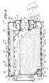
- Enfin, dans les formes de réalisation suivant la figure 4 une réalisation est représentée qui découle des précédentes mais dans laquelle le boîtier insonorisant 4 est plus haut et plus large et où il est indiqué, en traits mixtes 55, à quels endroits un matériau thermo-isolant 37 ou un soi-disant pont cryogène peut être prévu.
- Il est évident que l'on obtient une grille de ventilation insonorisante de cette manière que peut être réalisée dans des hauteurs et des largeurs différentes, dans laquelle on applique pratiquement toujours la même série de profilés constitutifs et dans laquelle à plusieurs endroits, d'après la construction désirée, un pont cryogène peut être prévu, d'une part, et où le passage d'air 52 peut être diminué ou augmenté afin d'influencer le débit de ventilation, d'une part, et le passage du bruit, d'autre part.
- Il est évident que la présente invention est en aucun cas limitée aux réalisations décrites en tant qu'exemple et représentées dans les dessins, mais qu'une telle grille rotative de ventilation insonorisante peut être réalisée dans tout genre de forme et de dimensions sans dépasser le cadre de la présente invention.
Claims (17)
Applications Claiming Priority (2)
| Application Number | Priority Date | Filing Date | Title |
|---|---|---|---|
| BE8800317A BE1002675A3 (nl) | 1988-03-21 | 1988-03-21 | Geluidsdempend draaiventilatierooster. |
| BE8800317 | 1988-03-21 |
Publications (3)
| Publication Number | Publication Date |
|---|---|
| EP0337975A2 true EP0337975A2 (fr) | 1989-10-18 |
| EP0337975A3 EP0337975A3 (en) | 1990-09-26 |
| EP0337975B1 EP0337975B1 (fr) | 1993-04-07 |
Family
ID=3883321
Family Applications (1)
| Application Number | Title | Priority Date | Filing Date |
|---|---|---|---|
| EP89870036A Expired - Lifetime EP0337975B1 (fr) | 1988-03-21 | 1989-03-02 | Dispositif de ventilation |
Country Status (3)
| Country | Link |
|---|---|
| EP (1) | EP0337975B1 (fr) |
| BE (1) | BE1002675A3 (fr) |
| DE (1) | DE68905853T2 (fr) |
Cited By (8)
| Publication number | Priority date | Publication date | Assignee | Title |
|---|---|---|---|---|
| NL1005260C2 (nl) * | 1997-02-12 | 1998-08-13 | Zwaan Adrianus J | Geluiddempende ventilatie-inrichting voorzien van een balkvormig huis met een spleetvormig ventilatiekanaal. |
| WO2000046555A1 (fr) * | 1999-02-03 | 2000-08-10 | Nemcek Milan | Dispositif d'aeration et d'insonorisation pour garnissage d'une ouverture |
| DE19701444C2 (de) * | 1996-01-22 | 2000-08-31 | Zwaan Adrianus J | Schalldämm-Lüftungsvorrichtung mit einem langgestreckten, kastenförmigen Gehäuse und einem schlitzförmigen Lüftungskanal |
| WO2001018458A1 (fr) * | 1999-09-03 | 2001-03-15 | Titon Hardware Limited | Ensembles de ventilation |
| EP1096097A1 (fr) * | 1999-10-26 | 2001-05-02 | CVA Aluproco | Dispositif de ventilation avec valve détachable |
| NL1017740C2 (nl) * | 2001-03-30 | 2002-10-01 | Vero Duco Nv | Muurdemper. |
| NL1029009C2 (nl) * | 2005-05-11 | 2006-11-14 | Renson Ventilation N V | Ventilatie-inrichting. |
| BE1020710A3 (nl) * | 2012-06-15 | 2014-04-01 | Renson Ventilation Nv | Verbeterde akoestische ventilatieinrichting. |
Family Cites Families (4)
| Publication number | Priority date | Publication date | Assignee | Title |
|---|---|---|---|---|
| DE2450480C3 (de) * | 1974-10-24 | 1981-05-07 | Theodor 8857 Gottmannshofen Straub | Lüftungsvorrichtung |
| CH653118A5 (en) * | 1980-09-29 | 1985-12-13 | Siegenia Frank Kg | Ventilation device for installation in windows or other wall openings of buildings |
| DE3301508C2 (de) * | 1982-03-11 | 1985-01-17 | Siegenia-Frank Kg, 5900 Siegen | Lüftungsvorrichtung für den Einbau in Fenster und/oder in andere Wandöffnungen von Gebäuden |
| DE8810175U1 (de) * | 1988-08-10 | 1988-09-22 | Gretsch-Unitas GmbH Baubeschläge, 7257 Ditzingen | Lüftungsvorrichtung |
-
1988
- 1988-03-21 BE BE8800317A patent/BE1002675A3/nl not_active IP Right Cessation
-
1989
- 1989-03-02 DE DE8989870036T patent/DE68905853T2/de not_active Expired - Fee Related
- 1989-03-02 EP EP89870036A patent/EP0337975B1/fr not_active Expired - Lifetime
Cited By (10)
| Publication number | Priority date | Publication date | Assignee | Title |
|---|---|---|---|---|
| DE19701444C2 (de) * | 1996-01-22 | 2000-08-31 | Zwaan Adrianus J | Schalldämm-Lüftungsvorrichtung mit einem langgestreckten, kastenförmigen Gehäuse und einem schlitzförmigen Lüftungskanal |
| NL1005260C2 (nl) * | 1997-02-12 | 1998-08-13 | Zwaan Adrianus J | Geluiddempende ventilatie-inrichting voorzien van een balkvormig huis met een spleetvormig ventilatiekanaal. |
| WO2000046555A1 (fr) * | 1999-02-03 | 2000-08-10 | Nemcek Milan | Dispositif d'aeration et d'insonorisation pour garnissage d'une ouverture |
| CZ296923B6 (cs) * | 1999-02-03 | 2006-07-12 | Otvorová výpln s vetracím a zvuk tlumicím zarízením pro prostory | |
| WO2001018458A1 (fr) * | 1999-09-03 | 2001-03-15 | Titon Hardware Limited | Ensembles de ventilation |
| US6648750B1 (en) | 1999-09-03 | 2003-11-18 | Titon Hardware Limited | Ventilation assemblies |
| EP1096097A1 (fr) * | 1999-10-26 | 2001-05-02 | CVA Aluproco | Dispositif de ventilation avec valve détachable |
| NL1017740C2 (nl) * | 2001-03-30 | 2002-10-01 | Vero Duco Nv | Muurdemper. |
| NL1029009C2 (nl) * | 2005-05-11 | 2006-11-14 | Renson Ventilation N V | Ventilatie-inrichting. |
| BE1020710A3 (nl) * | 2012-06-15 | 2014-04-01 | Renson Ventilation Nv | Verbeterde akoestische ventilatieinrichting. |
Also Published As
| Publication number | Publication date |
|---|---|
| EP0337975A3 (en) | 1990-09-26 |
| BE1002675A3 (nl) | 1991-04-30 |
| DE68905853D1 (de) | 1993-05-13 |
| EP0337975B1 (fr) | 1993-04-07 |
| DE68905853T2 (de) | 1993-07-15 |
Similar Documents
| Publication | Publication Date | Title |
|---|---|---|
| WO1984003320A1 (fr) | Element de revetement pour facade exterieure, son application et appareillage de grainage pour les profiles dudit element | |
| WO1991003617A1 (fr) | Panneau de façade a chassis metallique et façade revetue d'un tel panneau | |
| EP0337975B1 (fr) | Dispositif de ventilation | |
| BE512172A (fr) | ||
| EP3371519B1 (fr) | Installation pour la ventilation naturelle d'un local pourvue d'un amortisseur de bruit | |
| EP0001948A1 (fr) | Dispositif de maintien d'éléments de vitrage ou analogues | |
| FR2711697A1 (fr) | Ecran anti-effraction pour élément de cloison, élément de cloison et cloison anti-effraction. | |
| EP0277064B1 (fr) | Dispositif de ventilation permettant une isolation acoustique | |
| FR2624641A1 (fr) | Dispositif d'attenuation de la propagation des sons, pour bouches d'entree d'air | |
| FR2789101A1 (fr) | Dalle de plafond | |
| FR3043177B1 (fr) | Installation pour la ventilation naturelle d'un local | |
| EP0643192A1 (fr) | Ensemble de caisson de volet roulant | |
| EP0791700A1 (fr) | Platine-entretoise de fixation pour la réalisation de vêtages dans le domaine du bâtiment, et vêtages ainsi obtenus | |
| FR2672336A1 (fr) | Fenetre a vitrages multiples a isolation dynamique. | |
| FR2715673A1 (fr) | Mur antibruit. | |
| FR2683581A1 (fr) | Menuiserie coulissante thermo-acoustique. | |
| FR3043124B1 (fr) | Menuiserie du type porte ou fenetre equipee d'un volet roulant accessible de l'interieur | |
| FR2783864A1 (fr) | Ensemble caisson pour volet roulant notamment | |
| EP2261452B1 (fr) | Châssis de fermeture de type coulissant ou analogue | |
| FR2770573A3 (fr) | Entree d'air destinee a etre montee dans une fenetre ou equivalent | |
| WO1990008870A1 (fr) | Mezzanine a plancher mobile en hauteur | |
| EP0421841A1 (fr) | Dispositif pour le passage d'air et installation comportant un tel dispositif | |
| FR2607167A1 (fr) | Profile pour cadre de panneau, en particulier de plafond suspendu, de cloison ou d'habillage mural | |
| FR2632672A1 (fr) | Ecran d'absorption acoustique | |
| EP0953811A1 (fr) | Bouche d'aérage perfectionnée |
Legal Events
| Date | Code | Title | Description |
|---|---|---|---|
| PUAI | Public reference made under article 153(3) epc to a published international application that has entered the european phase |
Free format text: ORIGINAL CODE: 0009012 |
|
| AK | Designated contracting states |
Kind code of ref document: A2 Designated state(s): DE FR GB LU NL |
|
| PUAL | Search report despatched |
Free format text: ORIGINAL CODE: 0009013 |
|
| AK | Designated contracting states |
Kind code of ref document: A3 Designated state(s): DE FR GB LU NL |
|
| 17P | Request for examination filed |
Effective date: 19901221 |
|
| 17Q | First examination report despatched |
Effective date: 19911002 |
|
| GRAA | (expected) grant |
Free format text: ORIGINAL CODE: 0009210 |
|
| AK | Designated contracting states |
Kind code of ref document: B1 Designated state(s): DE FR GB LU NL |
|
| REF | Corresponds to: |
Ref document number: 68905853 Country of ref document: DE Date of ref document: 19930513 |
|
| GBT | Gb: translation of ep patent filed (gb section 77(6)(a)/1977) |
Effective date: 19930423 |
|
| PLBE | No opposition filed within time limit |
Free format text: ORIGINAL CODE: 0009261 |
|
| STAA | Information on the status of an ep patent application or granted ep patent |
Free format text: STATUS: NO OPPOSITION FILED WITHIN TIME LIMIT |
|
| 26N | No opposition filed | ||
| EPTA | Lu: last paid annual fee | ||
| PGFP | Annual fee paid to national office [announced via postgrant information from national office to epo] |
Ref country code: FR Payment date: 20000216 Year of fee payment: 12 |
|
| PGFP | Annual fee paid to national office [announced via postgrant information from national office to epo] |
Ref country code: LU Payment date: 20000218 Year of fee payment: 12 |
|
| PGFP | Annual fee paid to national office [announced via postgrant information from national office to epo] |
Ref country code: GB Payment date: 20000302 Year of fee payment: 12 |
|
| PGFP | Annual fee paid to national office [announced via postgrant information from national office to epo] |
Ref country code: DE Payment date: 20000306 Year of fee payment: 12 |
|
| PGFP | Annual fee paid to national office [announced via postgrant information from national office to epo] |
Ref country code: NL Payment date: 20000330 Year of fee payment: 12 |
|
| PG25 | Lapsed in a contracting state [announced via postgrant information from national office to epo] |
Ref country code: LU Free format text: LAPSE BECAUSE OF NON-PAYMENT OF DUE FEES Effective date: 20010302 Ref country code: GB Free format text: LAPSE BECAUSE OF NON-PAYMENT OF DUE FEES Effective date: 20010302 |
|
| PG25 | Lapsed in a contracting state [announced via postgrant information from national office to epo] |
Ref country code: NL Free format text: LAPSE BECAUSE OF NON-PAYMENT OF DUE FEES Effective date: 20011001 |
|
| GBPC | Gb: european patent ceased through non-payment of renewal fee |
Effective date: 20010302 |
|
| PG25 | Lapsed in a contracting state [announced via postgrant information from national office to epo] |
Ref country code: FR Free format text: LAPSE BECAUSE OF NON-PAYMENT OF DUE FEES Effective date: 20011130 |
|
| NLV4 | Nl: lapsed or anulled due to non-payment of the annual fee |
Effective date: 20011001 |
|
| REG | Reference to a national code |
Ref country code: FR Ref legal event code: ST |
|
| PG25 | Lapsed in a contracting state [announced via postgrant information from national office to epo] |
Ref country code: DE Free format text: LAPSE BECAUSE OF NON-PAYMENT OF DUE FEES Effective date: 20020101 |