EP0337983A1 - Verrou pour une porte - Google Patents
Verrou pour une porte Download PDFInfo
- Publication number
- EP0337983A1 EP0337983A1 EP89890109A EP89890109A EP0337983A1 EP 0337983 A1 EP0337983 A1 EP 0337983A1 EP 89890109 A EP89890109 A EP 89890109A EP 89890109 A EP89890109 A EP 89890109A EP 0337983 A1 EP0337983 A1 EP 0337983A1
- Authority
- EP
- European Patent Office
- Prior art keywords
- latch
- door
- bolt
- door lock
- lock according
- Prior art date
- Legal status (The legal status is an assumption and is not a legal conclusion. Google has not performed a legal analysis and makes no representation as to the accuracy of the status listed.)
- Granted
Links
- 230000000903 blocking effect Effects 0.000 abstract 1
- 230000000694 effects Effects 0.000 abstract 1
- 210000000056 organ Anatomy 0.000 description 1
Images

Classifications
-
- E—FIXED CONSTRUCTIONS
- E05—LOCKS; KEYS; WINDOW OR DOOR FITTINGS; SAFES
- E05B—LOCKS; ACCESSORIES THEREFOR; HANDCUFFS
- E05B81/00—Power-actuated vehicle locks
- E05B81/02—Power-actuated vehicle locks characterised by the type of actuators used
- E05B81/10—Hydraulic or pneumatic
-
- E—FIXED CONSTRUCTIONS
- E05—LOCKS; KEYS; WINDOW OR DOOR FITTINGS; SAFES
- E05B—LOCKS; ACCESSORIES THEREFOR; HANDCUFFS
- E05B81/00—Power-actuated vehicle locks
- E05B81/12—Power-actuated vehicle locks characterised by the function or purpose of the powered actuators
- E05B81/14—Power-actuated vehicle locks characterised by the function or purpose of the powered actuators operating on bolt detents, e.g. for unlatching the bolt
-
- E—FIXED CONSTRUCTIONS
- E05—LOCKS; KEYS; WINDOW OR DOOR FITTINGS; SAFES
- E05B—LOCKS; ACCESSORIES THEREFOR; HANDCUFFS
- E05B81/00—Power-actuated vehicle locks
- E05B81/54—Electrical circuits
- E05B81/64—Monitoring or sensing, e.g. by using switches or sensors
- E05B81/66—Monitoring or sensing, e.g. by using switches or sensors the bolt position, i.e. the latching status
- E05B81/68—Monitoring or sensing, e.g. by using switches or sensors the bolt position, i.e. the latching status by sensing the position of the detent
Definitions
- the invention relates to a door lock, in particular for vehicle doors, in which a preferably bolt-shaped bolt on the door leaf interacts with a pivotally attached latch on the door frame, which has a groove receiving the bolt and is under the action of a spring, the tension of which is determined by the closing of the Door occurring pivoting movement of the latch increased, the bolt arranged in the door leaf and the pivot axis of the latch being directed essentially parallel to both the door leaf and the door frame part carrying the latch. Furthermore, it is known that at least one catch is provided on the latch which can be pivoted by means of a pneumatic locking cylinder, into which a pawl which can be released by means of a pneumatic locking cylinder engages in the end region of the door closing movement.
- a catch groove is provided, the direction of which, seen parallel to the axis of rotation of the trap, is substantially perpendicular to the direction of the groove in the trap when the door is closed, optionally with at least one catch on the trap pivotable by means of a pneumatic locking cylinder is provided, in which a pawl detachable by means of a pneumatic locking cylinder engages in the end region of the door closing movement.
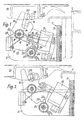
- FIG. 1 to 3 show a section along the line I - I in Fig. 5, etc. three phases of the door locking
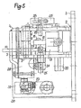
- Fig. 4 shows a section along the line IV - IV in Fig. 5
- Fig. 5 is a side view.
- a console designated as a whole by 2, which has a base plate 3 and two plates 4, 5 which are parallel to one another and perpendicular to it.
- the plate 4 is welded to a sleeve 6, in which a pin 7 is inserted and the lower end 8 of which is mounted in the lower plate 5.
- This has an arm 10a, onto which a bolt 11 is welded, which is articulated to the piston rod 12 of a pneumatic cylinder 13.
- This cylinder is pivotally mounted on the plates 4 and 5 by means of a pin 14.
- a compressed air line is connected to the cylinder 13 at 15.
- a torsion spring 16 is provided which surrounds the hub 9 and is supported at one end on a pin 17 and at the other end on a groove 18 of the latch 10. This spring tries to turn the latch in the direction of its opening pivot.
- the pin 17 forms a stop for this pivoting movement.
- the trap has a groove 19 which cooperates with a cylindrical bolt 20 of the door 21. Furthermore, two shoulders 22, 23 are featured on the trap see to which a pawl 24 can put on. This sits on a shaft 25 and is surrounded by a torsion spring 26 which pivots the pawl towards the latch 10.
- the shaft 25 carries an arm 26, which faces a pneumatic locking cylinder 28 with a shoulder 27. This is connected at 29 to a compressed air line, not shown.
- the console 2 has a vertical plate 30 which is welded to the base plate 3.
- the shaft 25 extends through the plate 4 upwards and carries a cam 33 there, which is indicated by dashed lines in FIGS. 1 to 3. It actuates the swivel arm 34 of a switch 35, which indicates the position of the locking link 24.
- Fig. 1 the locking device is shown in the open position of the door. If the door is closed, the bolt 20 runs onto the flank of the groove 19 of the latch 10 and pivots against the force of the torsion spring 16. The joint between the pin 11 and the piston rod 12 reaches the other side of the connecting plane E 1 and the locking cylinder 13 acted upon with compressed air now acts on the bolt 20 with the opposite flank of the groove 19 and supports the door closing movement in its end region.
- the bolt 32 of the door leaf enters the catch groove 31.
- the catch groove 31 and the bolt 32 prevent movement of the door leaf perpendicular to the catch groove.
- the latch 10 prevents a movement of the bolt 20 and thus of the door leaf 21 parallel to the catch groove 31 through its groove 19, since the direction of the grooves 19 and 31 are perpendicular to each other in the closed position of the door shown in the drawing.
- a Bowden cable 39 anchored at 38 which is connected to the end 40 of the arm 26 and which allows the arm 26 to be brought into the dashed position 37 by hand, serves as the emergency actuation device.
- Characteristic of the invention is the arrangement of the elements, such as catch groove 31, locking cylinder 28, latch 10 and pawl 24 and switch 35 in different levels. This results in a compact design. This arrangement of the elements does not have to match the arrangement shown.
- the pivot axis of the latch 10, the bolt 20 and the bolt 32 for the catch groove 31 will be substantially vertical.
- An exact vertical arrangement is not advisable if e.g. the door leaf is not flat and therefore deviates at least in part from the vertical direction. If the lock is arranged in the area of this part of the door leaf, the parts mentioned above will also deviate from the vertical direction.
Landscapes
- Lock And Its Accessories (AREA)
Applications Claiming Priority (2)
| Application Number | Priority Date | Filing Date | Title |
|---|---|---|---|
| AT0097188A AT393711B (de) | 1988-04-14 | 1988-04-14 | Tuerverriegelung |
| AT971/88 | 1988-04-14 |
Publications (2)
| Publication Number | Publication Date |
|---|---|
| EP0337983A1 true EP0337983A1 (fr) | 1989-10-18 |
| EP0337983B1 EP0337983B1 (fr) | 1993-03-03 |
Family
ID=3504007
Family Applications (1)
| Application Number | Title | Priority Date | Filing Date |
|---|---|---|---|
| EP89890109A Expired - Lifetime EP0337983B1 (fr) | 1988-04-14 | 1989-04-14 | Verrou pour une porte |
Country Status (3)
| Country | Link |
|---|---|
| EP (1) | EP0337983B1 (fr) |
| AT (1) | AT393711B (fr) |
| DE (1) | DE58903627D1 (fr) |
Cited By (3)
| Publication number | Priority date | Publication date | Assignee | Title |
|---|---|---|---|---|
| EP0965711A1 (fr) * | 1998-06-16 | 1999-12-22 | Dura Convertible Systems GmbH | Système de verrouillage pour capote de véhicule automobile |
| CN105464488A (zh) * | 2016-01-06 | 2016-04-06 | 南京海龙电气科技有限公司 | 塞拉门的门锁装置 |
| CN113550666A (zh) * | 2021-08-30 | 2021-10-26 | 中国第一汽车股份有限公司 | 一种汽车自吸合门锁及其控制方法 |
Families Citing this family (1)
| Publication number | Priority date | Publication date | Assignee | Title |
|---|---|---|---|---|
| CN105464483B (zh) * | 2016-01-06 | 2017-12-19 | 南京海龙电气科技有限公司 | 一种轨道交通拉塞门的门锁及其拉塞门 |
Citations (3)
| Publication number | Priority date | Publication date | Assignee | Title |
|---|---|---|---|---|
| US3942828A (en) * | 1974-04-18 | 1976-03-09 | R. Alkan & Cie | Electromechanical device cum manual control of safety outfit boxes on aircrafts |
| DE1919148B2 (de) * | 1969-04-15 | 1977-11-17 | Pfeiffer, Hans Walter, 5970 Plettenberg | Pneumatisch oder hydraulisch betaetigbare schliesshilfe fuer einen fahrzeug- tuerverschluss mit drehfalle |
| GB2048365A (en) * | 1979-04-07 | 1980-12-10 | Mitsui Mining & Smelting Co | Automobile door locking apparatus |
-
1988
- 1988-04-14 AT AT0097188A patent/AT393711B/de not_active IP Right Cessation
-
1989
- 1989-04-14 DE DE8989890109T patent/DE58903627D1/de not_active Expired - Lifetime
- 1989-04-14 EP EP89890109A patent/EP0337983B1/fr not_active Expired - Lifetime
Patent Citations (3)
| Publication number | Priority date | Publication date | Assignee | Title |
|---|---|---|---|---|
| DE1919148B2 (de) * | 1969-04-15 | 1977-11-17 | Pfeiffer, Hans Walter, 5970 Plettenberg | Pneumatisch oder hydraulisch betaetigbare schliesshilfe fuer einen fahrzeug- tuerverschluss mit drehfalle |
| US3942828A (en) * | 1974-04-18 | 1976-03-09 | R. Alkan & Cie | Electromechanical device cum manual control of safety outfit boxes on aircrafts |
| GB2048365A (en) * | 1979-04-07 | 1980-12-10 | Mitsui Mining & Smelting Co | Automobile door locking apparatus |
Cited By (6)
| Publication number | Priority date | Publication date | Assignee | Title |
|---|---|---|---|---|
| EP0965711A1 (fr) * | 1998-06-16 | 1999-12-22 | Dura Convertible Systems GmbH | Système de verrouillage pour capote de véhicule automobile |
| US6213534B1 (en) | 1998-06-16 | 2001-04-10 | Dura Convertible Systems Gmbh | Closure mechanism for the tops of vehicles |
| CN105464488A (zh) * | 2016-01-06 | 2016-04-06 | 南京海龙电气科技有限公司 | 塞拉门的门锁装置 |
| CN105464488B (zh) * | 2016-01-06 | 2018-05-18 | 南京海龙电气科技有限公司 | 塞拉门的门锁装置 |
| CN113550666A (zh) * | 2021-08-30 | 2021-10-26 | 中国第一汽车股份有限公司 | 一种汽车自吸合门锁及其控制方法 |
| CN113550666B (zh) * | 2021-08-30 | 2022-08-16 | 中国第一汽车股份有限公司 | 一种汽车自吸合门锁及其控制方法 |
Also Published As
| Publication number | Publication date |
|---|---|
| DE58903627D1 (de) | 1993-04-08 |
| AT393711B (de) | 1991-12-10 |
| ATA97188A (de) | 1991-05-15 |
| EP0337983B1 (fr) | 1993-03-03 |
Similar Documents
| Publication | Publication Date | Title |
|---|---|---|
| DE3447748C2 (fr) | ||
| DE2920581C3 (de) | Zusatzverriegelung, insbesondere Mittelverriegelung, für Fenster, Türen od.dgl. | |
| DE3142959C2 (de) | Treibstangenverschluß für Türen | |
| DE2639641C2 (de) | Bedienungsmechanismus für einen in einem Schaltschrank eingebauten elektrischen Schalter | |
| DE3400753C2 (de) | Außenschwingtür für Fahrzeuge und ihre Betätigungsvorrichtung | |
| DE4109852A1 (de) | Vorrichtung zum auf- und zumachen, insbesondere von vorzugsweise nach aussen zu oeffnenden ausstellfenstern | |
| EP1373668B1 (fr) | Dispositif de fixation | |
| EP0337983B1 (fr) | Verrou pour une porte | |
| EP0858541A2 (fr) | Dispositif de verrouillage | |
| DE4242877C2 (de) | Verschließeinrichtung für Türflügel von Gebäudetüren | |
| DE202007015667U1 (de) | Gebäudeabschluss mit Panik-Entriegelungselement in einbruchhemmender Ausführung | |
| DE3935990C2 (fr) | ||
| EP1970508A2 (fr) | Dispositif de blocage d'un élément pivotant d'un véhicule automobile | |
| DE3920498C2 (de) | Mehrfachverriegelung | |
| DE19906232B4 (de) | Vorrichtung zum Ver- und Entriegeln eines Standflügels | |
| DE19832356C2 (de) | Kantenriegelbeschlag | |
| DE3519229A1 (de) | Tuerschloss | |
| EP0505350A1 (fr) | Disque pivotant-séquence de fermeture et dispositif de verrouillage | |
| DE1264990B (de) | Tuerverschluss, insbesondere fuer Kraftwagen | |
| DE10108494C2 (de) | Vorrichtung zum Anziehen einer Tür oder eines Fensters an den Blendrahmen | |
| CH661090A5 (de) | Vorrichtung zum sichern von gegeneinander beweglichen teilen. | |
| EP3626918B1 (fr) | Ferrure pour une fenêtre, fenêtre | |
| DE3205486C2 (fr) | ||
| DE2758521C2 (de) | Treibstangenverschluß und Abdrückvorrichtung an einer waagerecht verschiebbaren Tür | |
| DE3137393A1 (de) | "fangvorrichtung fuer kraftbetaetigte tore" |
Legal Events
| Date | Code | Title | Description |
|---|---|---|---|
| PUAI | Public reference made under article 153(3) epc to a published international application that has entered the european phase |
Free format text: ORIGINAL CODE: 0009012 |
|
| AK | Designated contracting states |
Kind code of ref document: A1 Designated state(s): BE DE FR GB IT |
|
| 17P | Request for examination filed |
Effective date: 19891130 |
|
| 17Q | First examination report despatched |
Effective date: 19910723 |
|
| GRAA | (expected) grant |
Free format text: ORIGINAL CODE: 0009210 |
|
| AK | Designated contracting states |
Kind code of ref document: B1 Designated state(s): BE DE FR GB IT |
|
| REF | Corresponds to: |
Ref document number: 58903627 Country of ref document: DE Date of ref document: 19930408 |
|
| ITF | It: translation for a ep patent filed | ||
| ET | Fr: translation filed | ||
| GBT | Gb: translation of ep patent filed (gb section 77(6)(a)/1977) |
Effective date: 19930602 |
|
| PLBE | No opposition filed within time limit |
Free format text: ORIGINAL CODE: 0009261 |
|
| STAA | Information on the status of an ep patent application or granted ep patent |
Free format text: STATUS: NO OPPOSITION FILED WITHIN TIME LIMIT |
|
| 26N | No opposition filed | ||
| PGFP | Annual fee paid to national office [announced via postgrant information from national office to epo] |
Ref country code: FR Payment date: 19980318 Year of fee payment: 10 |
|
| PGFP | Annual fee paid to national office [announced via postgrant information from national office to epo] |
Ref country code: BE Payment date: 19980402 Year of fee payment: 10 |
|
| PG25 | Lapsed in a contracting state [announced via postgrant information from national office to epo] |
Ref country code: BE Free format text: LAPSE BECAUSE OF NON-PAYMENT OF DUE FEES Effective date: 19990430 |
|
| BERE | Be: lapsed |
Owner name: INDUSTRIE-EINRICHTUNGEN FERTIGUNGS-A.G. IFE Effective date: 19990430 |
|
| PG25 | Lapsed in a contracting state [announced via postgrant information from national office to epo] |
Ref country code: FR Free format text: LAPSE BECAUSE OF NON-PAYMENT OF DUE FEES Effective date: 19991231 |
|
| REG | Reference to a national code |
Ref country code: FR Ref legal event code: ST |
|
| REG | Reference to a national code |
Ref country code: GB Ref legal event code: IF02 |
|
| PGFP | Annual fee paid to national office [announced via postgrant information from national office to epo] |
Ref country code: GB Payment date: 20020412 Year of fee payment: 14 |
|
| PG25 | Lapsed in a contracting state [announced via postgrant information from national office to epo] |
Ref country code: GB Free format text: LAPSE BECAUSE OF NON-PAYMENT OF DUE FEES Effective date: 20030414 |
|
| GBPC | Gb: european patent ceased through non-payment of renewal fee |
Effective date: 20030414 |
|
| PG25 | Lapsed in a contracting state [announced via postgrant information from national office to epo] |
Ref country code: IT Free format text: LAPSE BECAUSE OF NON-PAYMENT OF DUE FEES;WARNING: LAPSES OF ITALIAN PATENTS WITH EFFECTIVE DATE BEFORE 2007 MAY HAVE OCCURRED AT ANY TIME BEFORE 2007. THE CORRECT EFFECTIVE DATE MAY BE DIFFERENT FROM THE ONE RECORDED. Effective date: 20050414 |
|
| PGFP | Annual fee paid to national office [announced via postgrant information from national office to epo] |
Ref country code: DE Payment date: 20080627 Year of fee payment: 20 |