EP0337996B1 - Debimetres a tourbillons emportes par le courant - Google Patents
Debimetres a tourbillons emportes par le courant Download PDFInfo
- Publication number
- EP0337996B1 EP0337996B1 EP87907799A EP87907799A EP0337996B1 EP 0337996 B1 EP0337996 B1 EP 0337996B1 EP 87907799 A EP87907799 A EP 87907799A EP 87907799 A EP87907799 A EP 87907799A EP 0337996 B1 EP0337996 B1 EP 0337996B1
- Authority
- EP
- European Patent Office
- Prior art keywords
- vortex
- bluff body
- flowmeter according
- shedding flowmeter
- separator
- Prior art date
- Legal status (The legal status is an assumption and is not a legal conclusion. Google has not performed a legal analysis and makes no representation as to the accuracy of the status listed.)
- Expired
Links
- 230000004888 barrier function Effects 0.000 claims abstract description 26
- 239000012530 fluid Substances 0.000 claims abstract description 19
- 239000007787 solid Substances 0.000 claims abstract description 10
- 230000001934 delay Effects 0.000 claims abstract description 3
- 238000011144 upstream manufacturing Methods 0.000 claims description 7
- 238000010079 rubber tapping Methods 0.000 claims description 4
- 239000000835 fiber Substances 0.000 claims description 2
- 230000000737 periodic effect Effects 0.000 claims 2
- 238000012545 processing Methods 0.000 description 6
- 238000001514 detection method Methods 0.000 description 2
- 238000003780 insertion Methods 0.000 description 2
- 230000037431 insertion Effects 0.000 description 2
- 238000000926 separation method Methods 0.000 description 2
- 230000015572 biosynthetic process Effects 0.000 description 1
- 230000000694 effects Effects 0.000 description 1
- 230000001788 irregular Effects 0.000 description 1
- 230000000873 masking effect Effects 0.000 description 1
- 238000005259 measurement Methods 0.000 description 1
- 239000002184 metal Substances 0.000 description 1
- 238000000034 method Methods 0.000 description 1
- 238000012986 modification Methods 0.000 description 1
- 230000004048 modification Effects 0.000 description 1
- 239000013307 optical fiber Substances 0.000 description 1
- 230000010355 oscillation Effects 0.000 description 1
Images



Classifications
-
- G—PHYSICS
- G01—MEASURING; TESTING
- G01F—MEASURING VOLUME, VOLUME FLOW, MASS FLOW OR LIQUID LEVEL; METERING BY VOLUME
- G01F1/00—Measuring the volume flow or mass flow of fluid or fluent solid material wherein the fluid passes through a meter in a continuous flow
- G01F1/05—Measuring the volume flow or mass flow of fluid or fluent solid material wherein the fluid passes through a meter in a continuous flow by using mechanical effects
- G01F1/20—Measuring the volume flow or mass flow of fluid or fluent solid material wherein the fluid passes through a meter in a continuous flow by using mechanical effects by detection of dynamic effects of the flow
- G01F1/32—Measuring the volume flow or mass flow of fluid or fluent solid material wherein the fluid passes through a meter in a continuous flow by using mechanical effects by detection of dynamic effects of the flow using swirl flowmeters
- G01F1/3209—Measuring the volume flow or mass flow of fluid or fluent solid material wherein the fluid passes through a meter in a continuous flow by using mechanical effects by detection of dynamic effects of the flow using swirl flowmeters using Karman vortices
- G01F1/3218—Measuring the volume flow or mass flow of fluid or fluent solid material wherein the fluid passes through a meter in a continuous flow by using mechanical effects by detection of dynamic effects of the flow using swirl flowmeters using Karman vortices bluff body design
Definitions
- This invention relates to vortex-shedding flowmeters.
- a vortex-shedding flowmeter consists essentially of two components: a "bluff body", the function of which is to generate a double stream of Karman vortices in the flowing fluid and an electrical device for detecting those vortices and transmitting an electric pulse to an electronic counter every time it senses the passage of a vortex.
- a "bluff body" the function of which is to generate a double stream of Karman vortices in the flowing fluid
- an electrical device for detecting those vortices and transmitting an electric pulse to an electronic counter every time it senses the passage of a vortex.
- the rate of emission of vortices and hence of electric pulses is directly proportional to the fluid flowrate past the bluff body.
- the extent to which this ideal is attained is known as the "linearity" of the flowmeter.
- the bluff body takes the form of a metal bar extending diametrally across the pipe. These are generally made with a "blockage ratio" - i.e. the fraction of the cross-sectional area of the pipe that is obstructed by the bluff body - of around 30 to 40 per cent. This results in a rather high pressure loss, which is disadvantageous, but attempts to construct such meters with substantially lower blockage ratios have not been successful, because their performance deteriorates when the blockage ratio is reduced.
- the essence of the invention is the discovery that the performance of a bluff body in the form of a vortex-shedding ring can be greatly improved if steps are taken to keep these two streams of vortices separate during the early stages of their formation, thus preventing them from mutual interference.
- This separation is accomplished according to the invention by providing a physical barrier between the two vortex streams. This barrier may be solid or it may be a fluid barrier, as will be explained hereinafter. (The separation of different vortices is known from GB-A-2132351, in which vortices shed by a rectangular bluff body may be interfered with by vortices shed by a tubular support for said body)
- a vortex-shedding flowmeter including an annular or ring-shaped vortex-generating bluff body, characterised by means to provide a barrier which at least delays mutual interference between the two streams of vortices generated respectively at the inside and outside surfaces of the bluff body.
- the said means may provide either a solid or a fluid barrier.
- the means preferably comprises a tubular or ring-shaped vortex separator so arranged that it keeps the two vortex streams physically separate.
- a fluid barrier is preferably provided by a second ring downstream of the bluff body and coaxial with it.
- a stagnation zone in the flowing fluid forms between the two rings and if the relative inside and outside diameters of the two rings and the spacing between them are correctly chosen, this stagnation zone will lie between the two streams of vortices and act as a fluid barrier to keep them apart.
- the ring-shaped bluff body is preferably circular when viewed in the direction of flow, so that its inside and outside circumferential surfaces are cylindrical, but it may be of other shapes, e.g. square, octagonal, hexagonal, or elliptical. Where a solid vortex separator is provided it is also preferably circular when viewed in the flow direction, but other shapes are likewise possible.
- each of the inner and outer annular surfaces of the bluff body may meet the corresponding surface of the vortex separator at a clearly defined edge or shoulder.
- the inner and outer surfaces of the bluff body may be cylindrical and the inner and outer surfaces of the vortex separator may for example be cylindrical or tapered.
- the separator may simply be a downstream extension of the bluff body with which it merges smoothly.
- the wall of the integral bluff body/separator may be of a wide variety of cross-sectional shapes, but all such shapes can be considered to be variations of three basic shapes, the rectangle, the triangle, and ellipse. A number of examples of specific shapes will be given hereinafter.
- the ratio of the length of the integral bluff body/separator in the direction of flow (l) to the difference between its inside and outside radii (d) should be within the range 0.5 to 0.7. In the case of a triangle or modified triangle l d should be 0.7 to 1.8.
- the basic rectangular or triangular shapes may be modified in various ways, for example by hollowing them out between their upstream and downstream extremities (so that a triangle becomes a tee and a rectangle an H or a C) or by cutting away or chamfering edges downstream of the upstream face.
- the gap between the two rings is preferably from 0.2d to 0.8d (d being defined as hereinabove) (more preferably 0.4d to 0.6d).
- both the bluff body and the vortex separator are circular when sectioned in a plane perpendicular to the flow direction, wherein at the interface between the bluff body and the vortex separator the inner surface of the bluff body is of smaller diameter than the inner surface of the vortex separator and the outer surface of the bluff body is of greater diamter than the outer surface of the vortex separator, and wherein the inner and outer surfaces of the vortex separator meet respectively at clearly-defined shoulders.
- Each half of the cross-section of the bluff body and vortex separator taken as a whole is therefore generally tee-shaped with the vortex separator forming the vertical leg of the tee.
- the vortex separator may be of constant cross-section, or may taper in the upstream or in the downstream direction. Further, the vortex separator may have an enlarged downstream end which has a smaller cross-sectional area than the bluff body.
- the difference between the inside diameters of the bluff body and the vortex separator is equal to the difference between the outside diameters of the bluff body and the vortex separator, but alternatively may be larger or smaller than the difference between the outside diameter of the bluff body and the vortex separator.
- l d ratio is preferably within the range 0.7 to 1.8, as for triangular cross sections as mentioned hereinbefore.
- a tee-shape can be considered as a modified triangle.
- both rings can have a wide variety of wall shapes.
- both rings may be relatively thin in the axial direction and of rectangular wall cross-section.
- the walls of either or both rings may be of tee-shaped cross section, and the or each tee cross-section ring can be arranged with the leg of the tee facing either upstream or downstream.
- the wall of the downstream ring may be of cruciform cross-section, with two legs of the cross parallel to the flow direction.
- the shape of the or each ring may be modified in a variety of ways.
- the surface may be curved, and/or the edges or corners may be cut away or rounded.
- the bluff body and vortex separator are preferably supported by one or more fins of streamlined or aerofoil cross-section, and/or by one or more supporting legs which extend transverse to the pipe axis between the inside of the pipe and the bluff body and vortex separator at a position downstream of the vortex separator.
- any of the known means of vortex detection may be used, including electro-thermal detectors, electro-mechanical detectors, ultrasonic detectors, electro-magnetic detectors, piezo-electric and fibre optic detectors.
- the invention especially facilitates the use of devices which detect the alternations of differential pressure across the, spearator that are associated with the shedding of vortices alternately from the inside and outside of the ring. This may be achieved in various ways, for example by installing one or more differential pressure detecting cells in the separator body, or by installing pressure tappings on either side of the separator body and connecting these via tubes or passages in the support(s) of the bluff body to a differential pressure cell mounted outside the pipe, to detect flow alternations arising from alternations in differential pressure.
- a thin separator ring it will periodically expand and contract slightly as the internal and external vortices are shed and these movements may be detected by one or more strain gauges attached to the separator; such a gauge may conveniently take the form of an annular wire resistance gauge or optical fibre at or near the downstream end of the separator ring.
- a fluid barrier there may be a flexible solid member or members projecting into the fluid stagnation zone; these will oscillate in resmance iwht the passage of vortices and the oscillations may be detected electrically with strain gauges or other means.
- the bluff body and its associated vortex separator are preferably in the form of cylinders with their axes parallel to the direction of the flow, since this will best preserve the axi-symmetrical nature of the flow past the ring.
- the fins or legs linking the bluff body and vortex separator to the pipe wall should preferably be radial, and the preferred number of fins is three at 120° intervals, except that in the special case of what is known to those skilled in the art as an "insertion meter" a single fin may be more appropriate.
- the fins should preferably not themselves shed vortices of such an intensity as to interfere with the normal working of the flowmeter, and as mentioned above it is therefore preferred to make the fins of substantially streamlined or aerofoil cross-section.
- the bluff body and vortex separator may be supported by one or more angled brackets whose radial portions are sufficiently far downstream to ensure that any vortices they shed are unable to affect the operation of the meter.
- the bluff body When installed in a pipe to form a flowmeter the bluff body should preferably be co-axial with the pipe, except that in the special case of an "insertion meter" other positions may sometimes be preferable.
- the "blockage ratio" (as defined herein) of a flowmeter according to this invention is preferably less than 20% and more preferably less than 10%.
- Flowmeters according to the invention preferably have a standard deviation of the intervals between successive pulses of not more than 5% and more preferably not more than 2.5%.
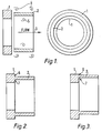
- Fig. 1 shows, in longitudinal section and also in rear elevation, a bluff body with a separate associated vortex separator.
- Figs. 2 and 3 show in longitudinal section bluff bodies with integral vortex separators.
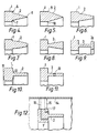
- Figs. 4 to 11 shows in partial longitudinal section alternative bluff bodies with integral vortex separators.
- Fig. 12 shows in partial longitudinal section a bluff body and means for connecting it to a differential pressure cell.
- Fig. 13 shows, in end elevation, a bluff body and vortex separator incorporating a strain gauge for detecting vortices.
- Fig. 14 shows a bluff body and vortex separator mounted on the inside of a pipe.
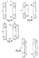
- Figs 15 to 18 show, in cross-section, various combinations of vortex-shedding bluff body and separate downstream ring to provide a fluid barrier to interference between the two streams of vortices.
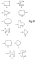
- Fig. 19 shows wall cross-sections of a variety of other rings which can be used either for the bluff body, or for a second downstream ring providing a fluid barrier to interference between the two streams of vortices, or both.
- Fig. 20 is a graph showing the effect on the linearity of the meter of varying l d for a tee-shaped integral bluff body and separator ring.
- Fig. 21 shows in schematic rear elevation a portion of a tee-shaped integral bluff body and separator ring showing strain gauges for detecting the passage of vortices.
- Fig. 1 shows a separate annular bluff body 1 and a cylindrial vortex separator 2 coaxial with it.
- a pipe not shown
- vortices will be created in fluid flowing along the pipe in the direction of the arrow 3.
- One stream of vortices 4 is formed at the outside surface of the bluff body 1, and a second stream 5 at the inside surface.
- Figs. 2 and 3 show alternative embodiments in which the bluff body 1 and the vortex separator 2 are integral.
- the bluff body and the separator meet at distinct outer and inner shoulders 6,7.
- the two shoulders 6,7 are of equal height, whereas, in Fig 3, shoulder 7 is substantially higher than shoulder 6.
- Fig. 4 shows an arrangement in which the separator 2 tapers from shoulders 6,7, where it meets the bluff body 1, to an annular edge 8 at its distal end.
- Fig. 5 shows a variant in which the bluff body 1 and separator 2 meet at edges 9,10 instead of shoulders.
- Figs. 6, 7, 8, and 9 show further variants all with tapering separators 2.
- Fig. 10 shows a variant with convexly-curved front and rear surfaces 11,12 on the bluff body 1.
- the convex front face of the bluff body may consist of two flat surface portions at a slight angle to one another and meeting at an edge.
- Fig. 11 shows a bluff body 1 and an integral separator 2 in which the separator 2 incorporates a differential pressure transducer 13 for detecting the pasage of vortices.
- Fig. 12 shows a bluff body 1 and integral separator 2 which is mounted on the inside wall of a pipe 14 by an aerofoil-shaped fin 15.
- the fin 15 and the bluff body 1 incorporate tappings 16, 17 to enable the pressure of the inside and outside rear surfaces of the bluff body to be sensed. These tappings are connected to a differential pressure cell or an anemometer (not shown) mounted outside the pipe.
- Fig. 13 shows a bluff body 1 and a vortex separator 2 incorporting an annular strain gauge 18 on the downstream end surface of the separator 2, for detecting the passage of vortices.
- Fig. 14 shows a bluff body 1 and integral vortex separator 2 which are supported within pipe 14 by angled supports 18 (of which there may be only one or more than the two shown) each of which comprise a radial portion 19 and an axial portion 20, with the radial portions downstream of the separator 2, so that any vortices created by it do not disturb the functioning of the flowmeter.
- Fig. 2 Three prototypes of a bluff body and integral vortex separator as shown in Fig. 2 have been tested in a wind tunnel of 305mm interval diameter, all with three-fin aerofoil supports and hot-wire vortex detectors. The best of these had a vortex-shedding ring with an outside diameter of 122mm, and inside diameter of 87mm and a length of 12mm, together with a separator ring of outside diameter 110mm, and inside diameter of 100mm and a length of 20mm.
- the blockage ratio of this meter was less than 10 per cent and the pressure drop caused by it was very much less than half that caused by conventional vortex-shedding meters, which customarily have blockage ratios in the region of 30 to 40 per cent.
- This meter was found to have a more regular pattern of pulse emission than any conventional meter.
- the standard deviation of the intervals between successive pulses was 2.5 per cent, compared with more than 10 per cent for the conventional meter tested under comparable conditions at the same time.
- This prototype was also found to have about twice the signal strength and about twice the signal-to-noise ratio of a conventional meter tested under comparable conditions at the same time.
- the linearity of the prototype was comparable with that of conventional meters; that is to say, it wa approaching 0.5 per cent over the range of Reynolds numbers (based on wind tunnel diameter) from 60,000 to 260,000.
- Figs. 15 to 18 show, respectively, four different arrangements of bluff body 1 and separator ring 2, where the separator ring is spaced from the bluff body so that a fluid barrier keeping the two streams of vortices shed by the inner and outer edges of the bluff body is formed in a stagnation zone 21 upstream of the front face of the ring 2.
- a bluff body of triangular or modified triangular wall cross-section may be considered to be equivalent to the rings of tee-shaped wall cross section shown in Figs. 15 to 18 and may therefore replace rings of the tee-shaped wall cross-sections shown in those figures.
- Fig. 19 shows a variety of further alternative wall cross-section shapes that may be employed instead of the cross-sections shown in Figs. 15 to 18. In each case the arrow shows the flow direction.
- Figs. 19d, f, and h show how the basic rectangular, tee-shaped, and triangular wall cross-sections, can be modified by cutting away or chamfering edges, especially downstream of the upstream face of the ring, and Figs. 19i,j,k, and 1, show modifications achieved by the rounding of surfaces.
- Fig. 20 is a graph showing the deviation from linearity (in %) plotted against the l d ratio (as explained hereinbefore) for an integral bluff body/vortex separator of tee-shaped wall cross-section. It shows that optimum linearity is obtained at an ratio,of about 1.3, although ratios in the range 0.7 to 1.8 are acceptable in practice.
- Fig. 21 shows an alternative means of detecting vortices by means of strain gauges. It is a rear elevation showing part of the vortex separator 2 within a pipe 14.
- the vortex separator has a very narrow axial split 22, the bluff body (not shown) may or may not also have a corresponding split.
- a pair of closely spaced cantilevered parallel supporting legs 23a, 23b, extends from the pipe wall to the vortex separator 2 so that they meet the separator 2 on opposite sides of the split 22.
- Two strain gauges 24a, 24b are mounted respectively on the legs 23a, 23b. The strain gauges are connected separately to signal processing means (not shown) outside the pipe.
- Known vortex shedding flowmeters are subject to vibration and vibration tends to give rise to signals which resemble those produced by the passage of Karman vortices. Thus, vibration can mask the signals produced by the vortices and reduce the sensity of the meter.
- the above signal-detecting means at least partially solves the problems caused by vibration. If the pipe 14 vibrates, the resulting vibrational movements of the bluff body/vortex separator tend to lag behind those of the pipe and thus the bluff body/vortex separator assembly tends to move bodily back and forth relative to the pipe 14. This will cause the two legs 23a, 23b to be deflected in the same direction (as shown in Fig. 21). Thus, prior to processing, the signals from the two associated strain gauges will be in phase.
- the vortex separator 2 may be suspended by more than one pair of legs 23a, 23b. For example, three pairs may be spaced around its circumference 120° apart. Strain gauges and the associated signal processing means as described above may be associated with two or more of such pairs of legs. If three sets of strain gauses and signal processing means is provided, for example, the three resulting sets of signals can be compared electronically and signals from a faulty set of strain gauges discarded.
Landscapes
- Physics & Mathematics (AREA)
- Fluid Mechanics (AREA)
- General Physics & Mathematics (AREA)
- Measuring Volume Flow (AREA)
Abstract
Claims (28)
Applications Claiming Priority (2)
| Application Number | Priority Date | Filing Date | Title |
|---|---|---|---|
| GB868628747A GB8628747D0 (en) | 1986-12-02 | 1986-12-02 | Vortex-shedding flowmeters |
| GB8628747 | 1986-12-02 |
Publications (2)
| Publication Number | Publication Date |
|---|---|
| EP0337996A1 EP0337996A1 (fr) | 1989-10-25 |
| EP0337996B1 true EP0337996B1 (fr) | 1992-05-06 |
Family
ID=10608287
Family Applications (1)
| Application Number | Title | Priority Date | Filing Date |
|---|---|---|---|
| EP87907799A Expired EP0337996B1 (fr) | 1986-12-02 | 1987-12-02 | Debimetres a tourbillons emportes par le courant |
Country Status (6)
| Country | Link |
|---|---|
| US (1) | US4984470A (fr) |
| EP (1) | EP0337996B1 (fr) |
| JP (1) | JPH02502668A (fr) |
| AU (1) | AU8329587A (fr) |
| GB (1) | GB8628747D0 (fr) |
| WO (1) | WO1988004410A1 (fr) |
Families Citing this family (15)
| Publication number | Priority date | Publication date | Assignee | Title |
|---|---|---|---|---|
| US5289726A (en) * | 1992-09-22 | 1994-03-01 | National Science Council | Ring type vortex flowmeter and method for measuring flow speed and flow rate using said ring type vortex flowmeter |
| US5351559A (en) * | 1993-08-31 | 1994-10-04 | National Science Council | T-shape vortex shedder wherein the bluff body extends across the diameter of a circular pipe and has a length to width ratio between 1.56 and 2.0 |
| JPH0989613A (ja) * | 1995-09-25 | 1997-04-04 | Smc Corp | 流量検出スイッチ |
| IE76714B1 (en) * | 1996-04-19 | 1997-10-22 | Auro Environmental Ltd | Apparatus for measuring the velocity of a fluid flowing in a conduit |
| WO1997048971A1 (fr) * | 1996-06-21 | 1997-12-24 | Hughes Technology Group L.L.C. | Debimetre massique |
| DE10118810A1 (de) * | 2001-04-17 | 2002-10-31 | Meinecke Ag H | Wirbelfrequenz-Strömungsmesser |
| US7600436B2 (en) * | 2006-07-21 | 2009-10-13 | Endress + Hauser Flowtec Ag | Measuring system with a flow conditioner arranged at an inlet of a measuring tube |
| KR100868046B1 (ko) | 2006-11-28 | 2008-11-11 | 주식회사 세 바 | 와류식 유량계 |
| TW200825382A (en) * | 2006-12-15 | 2008-06-16 | Univ Nat Taiwan | Eddy current precision flow meter |
| US7882751B2 (en) * | 2007-07-19 | 2011-02-08 | Endress + Hauser Flowtec Ag | Measuring system with a flow conditioner for flow profile stabilization |
| JP5463599B2 (ja) * | 2012-01-26 | 2014-04-09 | Smc株式会社 | フローセンサ |
| US9574916B2 (en) * | 2013-07-23 | 2017-02-21 | Yokogawa Corporation Of America | Optimized techniques for generating and measuring toroidal vortices via an industrial vortex flowmeter |
| US9279706B2 (en) * | 2013-07-23 | 2016-03-08 | Yokogawa Corporation Of America | Flow area reduction in Vortex flowmeters using bore reduction techniques |
| US9243940B2 (en) * | 2013-07-23 | 2016-01-26 | Yokogawa Corporation Of America | Optimized techniques for generating and measuring toroidal vortices via an industrial vortex flowmeter |
| US9599493B2 (en) * | 2014-10-31 | 2017-03-21 | Invensys Systems, Inc. | Split flow vortex flowmeter |
Family Cites Families (12)
| Publication number | Priority date | Publication date | Assignee | Title |
|---|---|---|---|---|
| USRE31217E (en) * | 1968-05-27 | 1983-04-26 | Neptune Eastech, Inc. | Bluff body flowmeter |
| DE2305813C3 (de) * | 1973-02-07 | 1980-02-21 | Fischer & Porter Gmbh, 3400 Goettingen | Durchflußmesser für ein von gasförmigen oder flüssigen Medien mit rotationssymmetrischer Geschwindigkeitsverteilung durchströmtes Rohr |
| US3972232A (en) * | 1974-04-24 | 1976-08-03 | The Foxboro Company | Vortex flow meter apparatus |
| GB1502260A (en) * | 1975-04-29 | 1978-03-01 | Kent Ltd G | Measurement of rates of flow of fluids |
| JPS5250262A (en) * | 1975-10-20 | 1977-04-22 | Yokogawa Hokushin Electric Corp | Device for measuring flow velocities |
| DE2802009A1 (de) * | 1978-01-18 | 1979-07-19 | Willi Dr Ing Gruender | Wirbeldurchflussmesser |
| US4226117A (en) * | 1979-02-21 | 1980-10-07 | Fischer & Porter Co. | Vortex-shedding flowmeter having drag-actuated torsional sensor |
| DE3125381C2 (de) * | 1981-06-27 | 1984-11-08 | Bopp & Reuther Gmbh, 6800 Mannheim | Strömungsmesser |
| US4584883A (en) * | 1981-11-10 | 1986-04-29 | Fuji Electric Company, Ltd. | Karman vortex flowmeter |
| GB2128325B (en) * | 1982-09-30 | 1986-08-06 | Mitsubishi Electric Corp | Karman's vortex street flow meter |
| US4455877A (en) * | 1982-09-30 | 1984-06-26 | Ford Motor Company | Vortex shedding mass air flow sensor with stabilized fluid flow |
| GB2132351A (en) * | 1982-12-17 | 1984-07-04 | Sarasota Automation | Vortex flowmeter |
-
1986
- 1986-12-02 GB GB868628747A patent/GB8628747D0/en active Pending
-
1987
- 1987-12-02 JP JP63500085A patent/JPH02502668A/ja active Pending
- 1987-12-02 US US07/375,017 patent/US4984470A/en not_active Expired - Fee Related
- 1987-12-02 AU AU83295/87A patent/AU8329587A/en not_active Abandoned
- 1987-12-02 WO PCT/GB1987/000866 patent/WO1988004410A1/fr not_active Ceased
- 1987-12-02 EP EP87907799A patent/EP0337996B1/fr not_active Expired
Also Published As
| Publication number | Publication date |
|---|---|
| GB8628747D0 (en) | 1987-01-07 |
| WO1988004410A1 (fr) | 1988-06-16 |
| JPH02502668A (ja) | 1990-08-23 |
| EP0337996A1 (fr) | 1989-10-25 |
| US4984470A (en) | 1991-01-15 |
| AU8329587A (en) | 1988-06-30 |
Similar Documents
| Publication | Publication Date | Title |
|---|---|---|
| EP0337996B1 (fr) | Debimetres a tourbillons emportes par le courant | |
| US5150619A (en) | Vortex flowmeters | |
| US4186599A (en) | Vortex shedding flowmeter assembly | |
| CA1324001C (fr) | Debitmetre a tourbillons pour fluide muni d'un levier en porte-a-faux amovible | |
| EP0619473B1 (fr) | Débitmètre à induction de vortex avec correction du nombre de Strohal avec deux ailes | |
| JP2602110B2 (ja) | 流体流量計 | |
| US4350047A (en) | Vortex-shedding flowmeter having two bluff bodies | |
| EP0547577B1 (fr) | Débitmètre à tourbillons avec deux ailes captrices | |
| US4003253A (en) | Multi-range vortex-shedding flowmeter | |
| US20150260553A1 (en) | Vortex shedding flow meter | |
| US4074571A (en) | Obstacle assembly for vortex type flowmeter | |
| US4485679A (en) | Fluid flowmeter | |
| US4030355A (en) | Obstacle assembly for vortex type flowmeter | |
| US4831883A (en) | Double bluff body vortex meter | |
| US4457181A (en) | Narrow profile vortex shedding body | |
| CA1099952A (fr) | Debitmetre generateur de vortex | |
| JP2869054B1 (ja) | 挿入形渦流量計及びそのプローブ管路の長さ決定方法 | |
| UA34492C2 (uk) | Вихровий витратомір для текучого середовища | |
| GB1598581A (en) | Flowmeters | |
| JP2004522159A (ja) | 渦周波数流量計 | |
| GB2101316A (en) | Improvement to vortex flow meter | |
| US4441372A (en) | Vortex flowmeter | |
| EP0309607B1 (fr) | Capteur de débit avec déflecteur générant des oscillations fluidiques | |
| CA1179528A (fr) | Debitmetre a turbulence | |
| JPS5845648B2 (ja) | 渦流型流量計 |
Legal Events
| Date | Code | Title | Description |
|---|---|---|---|
| PUAI | Public reference made under article 153(3) epc to a published international application that has entered the european phase |
Free format text: ORIGINAL CODE: 0009012 |
|
| 17P | Request for examination filed |
Effective date: 19890609 |
|
| AK | Designated contracting states |
Kind code of ref document: A1 Designated state(s): DE FR GB IT NL |
|
| 17Q | First examination report despatched |
Effective date: 19910603 |
|
| GRAA | (expected) grant |
Free format text: ORIGINAL CODE: 0009210 |
|
| ITF | It: translation for a ep patent filed | ||
| AK | Designated contracting states |
Kind code of ref document: B1 Designated state(s): DE FR GB IT NL |
|
| REF | Corresponds to: |
Ref document number: 3778914 Country of ref document: DE Date of ref document: 19920611 |
|
| ET | Fr: translation filed | ||
| PGFP | Annual fee paid to national office [announced via postgrant information from national office to epo] |
Ref country code: GB Payment date: 19921218 Year of fee payment: 6 |
|
| PGFP | Annual fee paid to national office [announced via postgrant information from national office to epo] |
Ref country code: NL Payment date: 19921231 Year of fee payment: 6 |
|
| PLBE | No opposition filed within time limit |
Free format text: ORIGINAL CODE: 0009261 |
|
| STAA | Information on the status of an ep patent application or granted ep patent |
Free format text: STATUS: NO OPPOSITION FILED WITHIN TIME LIMIT |
|
| 26N | No opposition filed | ||
| PG25 | Lapsed in a contracting state [announced via postgrant information from national office to epo] |
Ref country code: FR Effective date: 19930831 |
|
| PG25 | Lapsed in a contracting state [announced via postgrant information from national office to epo] |
Ref country code: DE Effective date: 19930901 |
|
| REG | Reference to a national code |
Ref country code: FR Ref legal event code: ST |
|
| PG25 | Lapsed in a contracting state [announced via postgrant information from national office to epo] |
Ref country code: GB Effective date: 19931202 |
|
| PG25 | Lapsed in a contracting state [announced via postgrant information from national office to epo] |
Ref country code: NL Effective date: 19940701 |
|
| GBPC | Gb: european patent ceased through non-payment of renewal fee |
Effective date: 19931202 |
|
| NLV4 | Nl: lapsed or anulled due to non-payment of the annual fee | ||
| PG25 | Lapsed in a contracting state [announced via postgrant information from national office to epo] |
Ref country code: IT Free format text: LAPSE BECAUSE OF NON-PAYMENT OF DUE FEES;WARNING: LAPSES OF ITALIAN PATENTS WITH EFFECTIVE DATE BEFORE 2007 MAY HAVE OCCURRED AT ANY TIME BEFORE 2007. THE CORRECT EFFECTIVE DATE MAY BE DIFFERENT FROM THE ONE RECORDED. Effective date: 20051202 |