EP0338111A1 - Verfahren zur Herstellung von sanitären Artikeln und Vorrichtung zur Durchführung dieses Verfahrens - Google Patents
Verfahren zur Herstellung von sanitären Artikeln und Vorrichtung zur Durchführung dieses Verfahrens Download PDFInfo
- Publication number
- EP0338111A1 EP0338111A1 EP88106424A EP88106424A EP0338111A1 EP 0338111 A1 EP0338111 A1 EP 0338111A1 EP 88106424 A EP88106424 A EP 88106424A EP 88106424 A EP88106424 A EP 88106424A EP 0338111 A1 EP0338111 A1 EP 0338111A1
- Authority
- EP
- European Patent Office
- Prior art keywords
- vacuum
- sheet
- fluid
- strip
- rotary drum
- Prior art date
- Legal status (The legal status is an assumption and is not a legal conclusion. Google has not performed a legal analysis and makes no representation as to the accuracy of the status listed.)
- Granted
Links
- 238000000034 method Methods 0.000 title claims abstract description 22
- 239000012530 fluid Substances 0.000 claims abstract description 60
- 210000001124 body fluid Anatomy 0.000 claims abstract description 21
- 239000010839 body fluid Substances 0.000 claims abstract description 19
- 239000000463 material Substances 0.000 claims description 28
- 230000002093 peripheral effect Effects 0.000 claims description 12
- 238000010438 heat treatment Methods 0.000 claims description 9
- 238000012546 transfer Methods 0.000 claims description 5
- 238000003825 pressing Methods 0.000 claims description 2
- 238000001816 cooling Methods 0.000 claims 6
- 238000007789 sealing Methods 0.000 claims 6
- 238000004891 communication Methods 0.000 claims 5
- 230000015572 biosynthetic process Effects 0.000 claims 2
- 230000000284 resting effect Effects 0.000 claims 2
- 230000013011 mating Effects 0.000 claims 1
- 239000002826 coolant Substances 0.000 description 6
- XLYOFNOQVPJJNP-UHFFFAOYSA-N water Substances O XLYOFNOQVPJJNP-UHFFFAOYSA-N 0.000 description 6
- 238000005520 cutting process Methods 0.000 description 5
- 238000004519 manufacturing process Methods 0.000 description 5
- 239000000835 fiber Substances 0.000 description 4
- 230000000694 effects Effects 0.000 description 3
- 239000011796 hollow space material Substances 0.000 description 2
- -1 polyethylene Polymers 0.000 description 2
- 239000000047 product Substances 0.000 description 2
- 238000007790 scraping Methods 0.000 description 2
- 239000004698 Polyethylene Substances 0.000 description 1
- 239000004743 Polypropylene Substances 0.000 description 1
- 238000010521 absorption reaction Methods 0.000 description 1
- 238000013459 approach Methods 0.000 description 1
- 210000004369 blood Anatomy 0.000 description 1
- 239000008280 blood Substances 0.000 description 1
- 230000000052 comparative effect Effects 0.000 description 1
- 238000007796 conventional method Methods 0.000 description 1
- 238000006073 displacement reaction Methods 0.000 description 1
- 239000004744 fabric Substances 0.000 description 1
- 239000008267 milk Substances 0.000 description 1
- 210000004080 milk Anatomy 0.000 description 1
- 235000013336 milk Nutrition 0.000 description 1
- 238000012986 modification Methods 0.000 description 1
- 230000004048 modification Effects 0.000 description 1
- 238000012856 packing Methods 0.000 description 1
- 230000035699 permeability Effects 0.000 description 1
- 239000012466 permeate Substances 0.000 description 1
- 229920000573 polyethylene Polymers 0.000 description 1
- 229920001155 polypropylene Polymers 0.000 description 1
- 239000002994 raw material Substances 0.000 description 1
- 230000000717 retained effect Effects 0.000 description 1
- 230000028327 secretion Effects 0.000 description 1
- 230000035939 shock Effects 0.000 description 1
- 238000011144 upstream manufacturing Methods 0.000 description 1
- 210000002700 urine Anatomy 0.000 description 1
Images


Classifications
-
- A—HUMAN NECESSITIES
- A61—MEDICAL OR VETERINARY SCIENCE; HYGIENE
- A61F—FILTERS IMPLANTABLE INTO BLOOD VESSELS; PROSTHESES; DEVICES PROVIDING PATENCY TO, OR PREVENTING COLLAPSING OF, TUBULAR STRUCTURES OF THE BODY, e.g. STENTS; ORTHOPAEDIC, NURSING OR CONTRACEPTIVE DEVICES; FOMENTATION; TREATMENT OR PROTECTION OF EYES OR EARS; BANDAGES, DRESSINGS OR ABSORBENT PADS; FIRST-AID KITS
- A61F13/00—Bandages or dressings; Absorbent pads
- A61F13/15—Absorbent pads, e.g. sanitary towels, swabs or tampons for external or internal application to the body; Supporting or fastening means therefor; Tampon applicators
- A61F13/15577—Apparatus or processes for manufacturing
- A61F13/15666—Wrapping formed fibrous webs or pads, e.g. the pads being formed by uniting pad pieces cut from fibrous webs
- A61F13/15674—Wrapping formed fibrous webs or pads, e.g. the pads being formed by uniting pad pieces cut from fibrous webs by wrapping webs or pads between webs moving in their longitudinal direction
-
- Y—GENERAL TAGGING OF NEW TECHNOLOGICAL DEVELOPMENTS; GENERAL TAGGING OF CROSS-SECTIONAL TECHNOLOGIES SPANNING OVER SEVERAL SECTIONS OF THE IPC; TECHNICAL SUBJECTS COVERED BY FORMER USPC CROSS-REFERENCE ART COLLECTIONS [XRACs] AND DIGESTS
- Y10—TECHNICAL SUBJECTS COVERED BY FORMER USPC
- Y10T—TECHNICAL SUBJECTS COVERED BY FORMER US CLASSIFICATION
- Y10T156/00—Adhesive bonding and miscellaneous chemical manufacture
- Y10T156/10—Methods of surface bonding and/or assembly therefor
- Y10T156/1089—Methods of surface bonding and/or assembly therefor of discrete laminae to single face of additional lamina
- Y10T156/1092—All laminae planar and face to face
- Y10T156/1093—All laminae planar and face to face with covering of discrete laminae with additional lamina
- Y10T156/1095—Opposed laminae are running length webs
-
- Y—GENERAL TAGGING OF NEW TECHNOLOGICAL DEVELOPMENTS; GENERAL TAGGING OF CROSS-SECTIONAL TECHNOLOGIES SPANNING OVER SEVERAL SECTIONS OF THE IPC; TECHNICAL SUBJECTS COVERED BY FORMER USPC CROSS-REFERENCE ART COLLECTIONS [XRACs] AND DIGESTS
- Y10—TECHNICAL SUBJECTS COVERED BY FORMER USPC
- Y10T—TECHNICAL SUBJECTS COVERED BY FORMER US CLASSIFICATION
- Y10T156/00—Adhesive bonding and miscellaneous chemical manufacture
- Y10T156/17—Surface bonding means and/or assemblymeans with work feeding or handling means
- Y10T156/1702—For plural parts or plural areas of single part
- Y10T156/1712—Indefinite or running length work
- Y10T156/1734—Means bringing articles into association with web
Definitions
- the present invention relates to a method of producing sanitary articles such as disposable diapers or the like for absorbing body fluids and an apparatus for carrying out the method, more particularly to method and apparatus for producing sanitary articles with improved efficiency.
- Sanitary articles used for absorbing body fluids include articles relating to birth, milk wiping materials, diapers, urine absorbing articles, supporters for various parts of the human body, wound bandages for ear, nose or other appendages of the human body.
- the main requirements for such sanitary articles include (1) the ability to maintain close contact with a complicated anatomical shape without displacement, (2) ease of absorption of excrement, blood, body fluids and secretions, (3) the ability to absorb shock and (4) air permeability.
- a sanitary article which satisfactorily meets these requirements is a paper diaper as illustrated in Fig. 6 which is a cross-sectional view and Fig. 7 which is an exploded perspective view.
- This sanitary article is usually layered, for example a layered structure having three layers including a body contact layer 70, a receptacle-shaped cover 72 for preventing body fluid from permeating into underclothing or the like and an absorptive pad 74 encased in a hollow space as defined therebetween for absorbing a body fluid.
- a thermally bonded fibrous body fluid permeable material such as paper, unwoven fabric or the like is used for the contact layer 70.
- a highly absorptive material such as water absorbing paper, cotton-like pulp or the like is used as the absorptive pad 74.
- a thermally fusible and body fluid impermeable material such as foamed polyethylene, foamed polypropylene or the like is employed in order to prevent body fluid from permeating into underclothing or the like.
- the cover 72 is shaped as a receptacle so as to accommodate the absorptive pad 74 in a hollow space.
- the cover 72 has a peripheral flange 76 formed integral therewith, and the contact member 70 and the flange 76 are thermally fused to one another to encase the absorptive pad 74 in the receptacle-shaped interior of the cover 72.
- a method of producing sanitary articles having three layers is disclosed in U.S. Patent No. 4,678,527 issued to John Ulman.
- a strip of thermally fusible and body fluid permeable sheet material and a strip of thermally fusible and body fluid impermeable sheet material are moved in parallel with one another at the same speed and a plurality of absorptive pads spaced by a fixed distance are positioned between the strips. Both the sheet strips are wider than the absorptive pads.
- the strips are thermally fused to one another with the use of a pair of pressing and heating tools in such a manner that the absorptive pads are encased therebetween.
- the thus assembled material is cut around the periphery of each encased absorptive pad.
- the cuts are made in areas where the two sheets are thermally fused together to produce the finished sanitary articles.
- the method of the Ulman patent offers the advantage that sanitary products can be produced by successive steps with high productive efficiency.
- two sheet strips are thermally fused in such a manner as to surround a plurality of absorptive pads, it follows that the finished products cannot maintain a constant configuration.
- the prior art sanitary article tends to deform during usage and to be displaced from the position where it is applied.
- a method producing covers which assure that sanitary articles maintain a predetermined configuration at all times was proposed by U.S. Patent No. 4,592,708 issued to Feist et al.
- a drum is formed with a plurality of cavities on its peripheral surface, each of which has a configuration identical to that of the cover to be produced, and fibers serving as raw material for the cover are injected into each cavity at a high speed.
- a vacuum is maintained in the interior of the drum in order to prevent the fibers from falling off during rotation of the drum.
- excess fiber is cut off by means of a scraping roll or cutting cylinder whereby a cover having a required shape is obtained.
- the cover is removed from the drum against the effect of negative pressure by an air jet emanating from a blow-off nozzle.
- the method of patent is intended to produce only covers adapted to maintain a predetermined configuration for sanitary articles.
- uniformity in the step of scraping or cutting the fibers is difficult or impossible to achieve.
- the method of the patent is intended to produce only covers as mentioned above, sanitary articles cannot be produced in closely related successive steps, resulting in lower production efficiency.
- the present invention has been made with the foregoing background in mind and with the objective of providing method and apparatus for producing sanitary articles automatically in a succession of steps with a low production cost per piece.
- the present invention utilizes (1) a sheet strip of a body fluid permeable material adapted to contact the human body, (2) a sheet strip of a thermally deformable, body fluid impermeable material for producing covers for preventing body fluid from permeating into underclothing or the like and (3) a plurality of absorptive pads in which body fluid is absorbed and retained.
- the strip of fluid permeable sheet for body contact and the strip of fluid impermeable sheet for the covers are thermally fused or adhered to one another in such a manner that the absorptive pads are encased in a plurality of pockets defined between the two strips.
- the strip of fluid impermeable sheet is heated to an elevated temperature at which it becomes deformable, and at that elevated temperature is shaped to form a series of spaced pockets suitable for receiving the absorptive pads.
- These pockets are formed by drawing the strip of the heated fluid impermeable sheet into the interiors of a series of cavities, i.e. in dies, under an effective negative pressure (vacuum).
- a plurality of absorptive pads are spaced along a strip of a fluid permeable sheet and are brought into registration with the pockets formed in the strip of fluid impermeable sheet to encase the absorptive pads in those pockets by thermally fusing or adhering the two superposed sheets together around the periphery of each pocket.
- the finished sanitary articles are formed by making successive cuts across th width of the assembled laminate strip in the bonded area between adjacent pockets.
- the apparatus includes heating means for heating the fluid impermeable sheet up to an elevated temperature at which it becomes deformable and a drum formed of a stationary flange and a rotary drum portion around which a plurality of dies are provided in an equispaced relationship.
- Each of the dies has a cavity of a shape corresponding to a pocket for encasing an absorptive pad.
- the apparatus further includes means for transfering the fluid impermeable sheet while the latter is wound around the rotary drum, means for drawing the heated fluid impermeable sheet into the interiors of the die cavities and means for feeding the fluid permeable sheet with a plurality of absorptive pads placed thereon so that the fluid impermeable sheet is superimposed on the fluid permeable sheet in such a manner that each absorptive pad is covered by a pocket.
- Means for thermally fusing or adhering the sheets together to form a seal surrounding each pocket and absorptive pad, and means for severing the thus assembled elements to separate the encased absorptive pads are also provided.
- the strip of fluid impermeable sheet is wound round about half of the circumference of the rotary drum. Five stations or positions on the circumference of the drum are important here. At a first position, the fluid impermeable sheet makes contact with and starts to be wound around the rotary drum. The fluid impermeable sheet is partially deformed toward the interior of the die cavity under the effect of a comparatively low intensity negative pressure as it approaches the second position. At the second position, the impermeable sheet is drawn completely to the bottom of the die cavity under a comparative high intensity of negative pressure whereby the fluid impermeable sheet is deformed to a configuration identical that of the die cavity.
- the deformed sheet is still subjected to a comparatively low intensity of negative pressure so as to inhibit the deformed sheet from falling away from the die cavity due to dead weight of the sheet.
- absorptive pads are successively introduced into the pockets formed in the fluid impermeable sheet and at the same time the strip of fluid permeable sheet is brought into contact with the strip of fluid impermeable sheet whereby an assembly having the absorptive member encased therein is built.
- the superposed sheets with the absorptive pads encased therebetween leave the rotary drum and are transferred to a cutter which separates the assembly into the finished sanitary articles.
- the comparatively low intensity vacuum may be conveniently generated by a blower, while the comparatively high intensity vacuum may be conveniently generated by a rotary pump.
- a plurality of air suction spaces adapted to be closed by the dies are formed on the outer peripheral surface of the rotary drum. Each of the air suction spaces communicates with the die cavity via air suction holes extending through the die and with a vacuum source.
- a coolant circulating pipe is provided in the interior of each of the air suction spaces so as to cool the fluid impermeable sheet.
- a conveyor for transfering the fluid permeable sheet is arranged near the bottom of the rotary drum and a plurality absorptive pads are successively placed on the moving upper run of the conveyor with equal spacing.
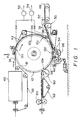
- Fig. 1 provides an overall view of the apparatus and method for producing sanitary articles which constitute the present invention.
- a drum 10 Central to the apparatus is a drum 10 which is supported for rotation in a conventional manner by means which is not shown in the drawings.
- the drum 10 includes a stationary flange 12 and a rotary drum 16 adapted to be rotationally driven by a motor 14 which is mounted on the stationary flange 12.
- a number of forming dies 18 cover the entire peripheral surface of the rotary drum 16 and are held in place by means of bolts 20.
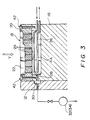
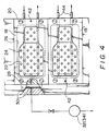
- Each of the dies 18 is formed with a cavity 22 at the central part of the outward facing surface of a shape corresponding to that of cover 72 of the sanitary article shown in Figs. 6 and 7. Further, each die 18 is formed with a number of air holes 24 which extend between the outer forming surface within cavity 22 to the rear surface of the die.
- a number of vacuum header spaces 26 adapted to be closed by the dies 18 are formed on the outer peripheral surface of the rotary drum 16. Each of the vacuum header spaces 26 communicates with the cavity 22 via the air suction holes 24.
- a vacuum passage 28 extends from the air suction space 26 to the face of the rotary drum 16 in contact with the stationary flange 12.
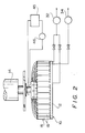
- the stationary flange 12 is formed with three vacuum grooves 30 arranged in three spaced positions 12a, 12b and 12c on the face of the flange 12 which is flush against rotary drum portion 16. These grooves 30 communicate with air suction passages 28 in the rotary drum 16 at a first position 12a located in the proximity of the top of drum 10, a second position 12b spaced from the first position 12a by an angle of about 70 degrees and a third position 12c spaced away from the first position 12a by an angle of about 120 degrees.
- the air suction grooves 30 located at the first position 12a and the third position 12c communicate with the suction side of a blower 32, which also performs another function as described below, whereby a first negative pressure is established in the air suction grooves 30.
- the air suction groove 30 located at the second position 12b communicates with the suction side of a rotary pump 34 which is designed and constructed to generate a second negative pressure lower than the negative pressure produced by blower 32. Consequently, a higher degree of vacuum is established in the air suction groove 30 located at the second position than that established in the air suction grooves 30 located at the first and third positions 12a and 12c.
- an endless belt 38 feeds the drum 10 with a strip of material 36 for forming covers 72, as shown in Fig. 6.
- a far-infrared ray heating unit 70 is also provided upstream of the drum 10.
- the strip of material 36 is heated in the heating unit 40 to an elevated temperature at which it becomes deformable and it is then fed to the drum 10 with the aid of the transfer belt 38.
- the heating unit 40 may optionally heat in a plurality of stages. It should be noted that the transfer belt 38 is driven at the same linear speed as the periphery speed of the rotary drum 16 by means of the motor 14.
- the sheet 36 is wound around approximately half the circumference of the rotary drum 16, with contact extending from the first position 12a located proximate the top to a fourth position 12d proximate the bottom of the rotary drum 16, whereby the upper surfaces of the dies 18 mounted on the periphery of the rotary drum 16 within that area of contact are covered with the sheet 36.
- two upwardly projecting pins 42 are provided on opposite sides of the upper surface of each of the dies 18 so that they impale the sheet 36 so as to prevent the sheet 36 from shifting on the surface of the rotary drum 16 in a manner which might otherwise frustrate the intended objective of thermal deformation.
- the relatively low intensity vacuum is established within the air suction space 26 on the rotary drum 16 by operation of the blower 32, and the vacuum is transmitted to the cavity 22 in the die 18 via the air suction holes 24.
- the sheet 36 which has been heated up to an elevated temperature at which it becomes deformable is brought into close contact with the outer surfaces of the dies 18 by the thus generated vacuum. Since the suction force produced by the blower 32 is weak, the sheet 36 over the cavity 22 enters only partially into the interior of the cavity 22. In other words, the sheet 36 is subjected to preliminary forming at the first position 12a.
- a coolant circulating pipe 44 is provided in the interior of each of the air suction spaces 26 formed on the outer peripheral surface of the rotary drum 16.
- coolant is introduced into the coolant circulating pipe 44 from a coolant pump 46 via a coolant tank 45 as a constant flow whereby the rotary drum 16 itself and the sheet 36 wound around the rotary drum 16 are cooled by indirect heat exchange. This results in the sheet 36 being completely cooled before it reaches the fourth position 12d at the bottom of the drum 10.
- the sheet 36 has reached the fourth position 12d, it has formed therein a succession of shaped pockets 72 having the same configuration as that of the cavities 22, arranged in an equally spaced linear relationship.
- a conveyor 50 feeds a strip 48, providing contact layer 70, tangentially onto the surface of rotary drum 16 at a point located in the proximity of the fourth position 12d at the bottom of the drum 10.
- Unit 52 feeds water absorptive pads 74 onto the sheet 48 with constant spacing onto the sheet 48. As seen in Fig. 1, unit 52 is located to the side of the conveyor 50. The constant distance between the adjacent water absorptive pads 74 is identical to the distance between the adjacent cavities 22 on the outer peripheral surface of the rotary drum 16.
- the sheet 48 With a number of water absorptive pads 74 placed on the sheet 48 in an equally spaced relationship, the sheet 48 is brought in contact with the sheet 36 wound around the rotary drum 16 at a point located in the proximity of the fourth position 12d at the bottom of the drum 10. Each water absorptive pad 74 placed on the sheet 48 is thereby introduced snugly into a recess formed in the sheet 36 by the cavity 22 of the die 18 slightly before the sheet 48 contacts the sheet 36.
- a heat seal roller 56 carries a plurality of frame-shaped projections 54 circumscribing an area larger than that of a cavity 22 (see Fig. 5).
- the heat seal roller 56 is positioned below the fourth position 12d on the drum 10.
- the sheet 36 is thermally fused to the sheet 48 with the aid of the heat seal roller 56 with the water absorptive pad 74 encased within the interior of the thermally fused structure.
- the rotational speed of the heat seal roller 56 is set so that the frame-shaped projection 54 correctly contacts rotary drum 16 around the periphery of the cavity 22 on the die 18.
- a retaining roller 58 is disposed downstream and adjacent to the heat seal roller 56. This retaining roller 58 is intended to prevent the fused assembly, including sheets 36 and 48 from breaking contact with the surface of the rotary drum 16.
- the fused assembly of the sheets 36 and 48 is removed from the rotary drum 16 at a position 12e located remote from the fourth position 12d and is received on a conveyor 62 via a roller 60.
- a cutter 64 for cutting the fused assembly of the sheets 36 and 48 around the periphery of each pad 74 is provided at the terminal end of the conveyor 62 for cutting the laminate strip to produce the finished sanitary articles.
- the finished sanitary articles are transferre to a packing station by a conveyor (not shown) disposed downstream of the cutter 64.
Landscapes
- Health & Medical Sciences (AREA)
- Engineering & Computer Science (AREA)
- Vascular Medicine (AREA)
- Epidemiology (AREA)
- Biomedical Technology (AREA)
- Heart & Thoracic Surgery (AREA)
- Manufacturing & Machinery (AREA)
- Life Sciences & Earth Sciences (AREA)
- Animal Behavior & Ethology (AREA)
- General Health & Medical Sciences (AREA)
- Public Health (AREA)
- Veterinary Medicine (AREA)
- Absorbent Articles And Supports Therefor (AREA)
Priority Applications (3)
| Application Number | Priority Date | Filing Date | Title |
|---|---|---|---|
| EP88106424A EP0338111B1 (de) | 1988-04-21 | 1988-04-21 | Verfahren zur Herstellung von sanitären Artikeln und Vorrichtung zur Durchführung dieses Verfahrens |
| DE8888106424T DE3882131D1 (de) | 1988-04-21 | 1988-04-21 | Verfahren zur herstellung von sanitaeren artikeln und vorrichtung zur durchfuehrung dieses verfahrens. |
| US07/196,622 US4874456A (en) | 1988-04-21 | 1988-05-19 | Vacuum drum apparatus for providing sanitary articles |
Applications Claiming Priority (1)
| Application Number | Priority Date | Filing Date | Title |
|---|---|---|---|
| EP88106424A EP0338111B1 (de) | 1988-04-21 | 1988-04-21 | Verfahren zur Herstellung von sanitären Artikeln und Vorrichtung zur Durchführung dieses Verfahrens |
Publications (2)
| Publication Number | Publication Date |
|---|---|
| EP0338111A1 true EP0338111A1 (de) | 1989-10-25 |
| EP0338111B1 EP0338111B1 (de) | 1993-06-30 |
Family
ID=8198906
Family Applications (1)
| Application Number | Title | Priority Date | Filing Date |
|---|---|---|---|
| EP88106424A Expired - Lifetime EP0338111B1 (de) | 1988-04-21 | 1988-04-21 | Verfahren zur Herstellung von sanitären Artikeln und Vorrichtung zur Durchführung dieses Verfahrens |
Country Status (3)
| Country | Link |
|---|---|
| US (1) | US4874456A (de) |
| EP (1) | EP0338111B1 (de) |
| DE (1) | DE3882131D1 (de) |
Cited By (3)
| Publication number | Priority date | Publication date | Assignee | Title |
|---|---|---|---|---|
| WO2001056522A1 (es) * | 2000-02-01 | 2001-08-09 | Comercial De Tecnologia Sanitaria, S.A. | Máquina para la fabricación de productos multicapa, tales como compresas, protectores higiénicos o apósitos |
| WO2002036056A3 (en) * | 2000-10-23 | 2003-09-04 | Kimberly Clark Co | Forming receptacle |
| KR20110139733A (ko) * | 2009-04-03 | 2011-12-29 | 유니챰 가부시키가이샤 | 흡수성 물품 제조 장치 및 흡수성 물품 제조 방법 |
Families Citing this family (13)
| Publication number | Priority date | Publication date | Assignee | Title |
|---|---|---|---|---|
| US5061334A (en) * | 1989-01-04 | 1991-10-29 | United States Tobacco Company | Machine and method for high speed, precisely registered label application with sprockets for positioning the label on a transfer wheel |
| US5081819A (en) * | 1989-12-04 | 1992-01-21 | Cloud Corporation | Method and apparatus for manufacture and packaging of filter packs for use in a brew basket |
| US6088081A (en) * | 1997-03-27 | 2000-07-11 | Konica Corporation | Image recording apparatus |
| CN100381272C (zh) * | 2001-07-24 | 2008-04-16 | 北京航空工艺研究所 | 一种提高真空渗透成形复合材料结构质量的工艺方法 |
| US20070034629A1 (en) * | 2003-10-22 | 2007-02-15 | Mazzarolo Ivonis M | Method of manufacturing thermoformed plastic articles and drink cup lid made by such method |
| US8038432B2 (en) * | 2003-10-23 | 2011-10-18 | Mazzarolo Ivonis M | Method of manufacturing thermoformed plastic articles and drink cup lid made by such method |
| US8628319B2 (en) | 2002-07-29 | 2014-01-14 | Ivma Holdings Company | Apparatus for manufacturing thermoformed plastic articles |
| US7021918B1 (en) * | 2005-02-07 | 2006-04-04 | Reum Sr Donald J | Apparatus for shaping and perforating a plastic film |
| US8007269B1 (en) * | 2006-01-24 | 2011-08-30 | Future Mold Corporation | Rotary forming wheel |
| US8840390B2 (en) * | 2007-06-29 | 2014-09-23 | Risco Usa Corporation | Machine for the production of formed patties with a hand made appearance, and method for interleaving paper and stacking |
| FR2964833B1 (fr) * | 2010-09-20 | 2012-10-12 | Marel Stork Food Systems France Sas | Machine de formage de portions de produit alimentaire avec dispositif d'application de papier intercalaire |
| EP2685950B1 (de) * | 2011-03-17 | 2015-08-26 | First Quality Baby Products, LLC | Verfahren und vorrichtung zum falten einer hosenähnlichen windel |
| EP2532777A1 (de) * | 2011-05-19 | 2012-12-12 | Autoneum Management AG | Vorrichtung zum Formen von faserigem Material |
Citations (4)
| Publication number | Priority date | Publication date | Assignee | Title |
|---|---|---|---|---|
| GB2103933A (en) * | 1981-08-20 | 1983-03-02 | Smith & Nephew Ass | Absorbent pad with perforated cover |
| FR2521003A1 (fr) * | 1982-02-05 | 1983-08-12 | Schickedanz Ver Papierwerk | Procede et dispositif pour la fabrication de garnitures hygieniques pour dames et garnitures ainsi obtenues |
| WO1985004366A1 (en) * | 1984-04-02 | 1985-10-10 | Johnson Carl W | Apparatus for forming fibrous pads |
| DE3508344A1 (de) * | 1985-03-08 | 1986-09-11 | Winkler & Dünnebier, Maschinenfabrik und Eisengießerei GmbH & Co KG, 5450 Neuwied | Maschine zur herstellung von kissenfoermigen, saugfaehigen einlagen |
Family Cites Families (12)
| Publication number | Priority date | Publication date | Assignee | Title |
|---|---|---|---|---|
| US1481866A (en) * | 1921-11-10 | 1924-01-29 | Penn Rubber Products Corp | Method of and apparatus for covering cores |
| NL214709A (de) * | 1956-02-21 | |||
| US2888787A (en) * | 1957-01-11 | 1959-06-02 | William S Cloud | Method and apparatus for vacuum packing in plastic |
| US2935828A (en) * | 1957-04-16 | 1960-05-10 | Standard Packing Corp | Continuous vacuum packaging machine |
| US3044117A (en) * | 1959-09-21 | 1962-07-17 | Goodyear Aircraft Corp | Apparatus for making fiber-resin parts |
| US3091808A (en) * | 1960-02-19 | 1963-06-04 | Gen Motors Corp | Vacuum forming drum |
| US3353329A (en) * | 1964-08-11 | 1967-11-21 | Cloud Machine Corp | Method of and apparatus for packaging elongated articles such as nipples |
| US3931383A (en) * | 1973-04-13 | 1976-01-06 | General Plastics Corporation | Method for continuously forming plastic sheet with vacuum pressure |
| US4016628A (en) * | 1973-05-14 | 1977-04-12 | Scott Paper Company | Method and apparatus for forming absorbent articles |
| IT1034836B (it) * | 1975-04-04 | 1979-10-10 | Fameccanica Spa | Procedimento macchina e relativi prodotti ottenuti nel settore igienico |
| US4678527A (en) * | 1984-09-17 | 1987-07-07 | Personal Products Company | Method for making nonplanar absorbent products |
| US4576669A (en) * | 1984-11-09 | 1986-03-18 | Caputo Garry L | "On demand" apparatus and method for producing air-cushioning product |
-
1988
- 1988-04-21 EP EP88106424A patent/EP0338111B1/de not_active Expired - Lifetime
- 1988-04-21 DE DE8888106424T patent/DE3882131D1/de not_active Expired - Lifetime
- 1988-05-19 US US07/196,622 patent/US4874456A/en not_active Expired - Lifetime
Patent Citations (4)
| Publication number | Priority date | Publication date | Assignee | Title |
|---|---|---|---|---|
| GB2103933A (en) * | 1981-08-20 | 1983-03-02 | Smith & Nephew Ass | Absorbent pad with perforated cover |
| FR2521003A1 (fr) * | 1982-02-05 | 1983-08-12 | Schickedanz Ver Papierwerk | Procede et dispositif pour la fabrication de garnitures hygieniques pour dames et garnitures ainsi obtenues |
| WO1985004366A1 (en) * | 1984-04-02 | 1985-10-10 | Johnson Carl W | Apparatus for forming fibrous pads |
| DE3508344A1 (de) * | 1985-03-08 | 1986-09-11 | Winkler & Dünnebier, Maschinenfabrik und Eisengießerei GmbH & Co KG, 5450 Neuwied | Maschine zur herstellung von kissenfoermigen, saugfaehigen einlagen |
Cited By (7)
| Publication number | Priority date | Publication date | Assignee | Title |
|---|---|---|---|---|
| WO2001056522A1 (es) * | 2000-02-01 | 2001-08-09 | Comercial De Tecnologia Sanitaria, S.A. | Máquina para la fabricación de productos multicapa, tales como compresas, protectores higiénicos o apósitos |
| ES2169648A1 (es) * | 2000-02-01 | 2002-07-01 | Com De Tecnologia Sanitaria S | Maquina para la fabricacion de productos multicapa, tales como compresas, salvaslips o apositos. |
| WO2002036056A3 (en) * | 2000-10-23 | 2003-09-04 | Kimberly Clark Co | Forming receptacle |
| US6630088B1 (en) | 2000-10-23 | 2003-10-07 | Kimberly-Clark Worldwide, Inc. | Forming media with enhanced air flow properties |
| KR20110139733A (ko) * | 2009-04-03 | 2011-12-29 | 유니챰 가부시키가이샤 | 흡수성 물품 제조 장치 및 흡수성 물품 제조 방법 |
| EP2415432A4 (de) * | 2009-04-03 | 2015-11-04 | Uni Charm Corp | Vorrichtung zur herstellung saugfähiger artikel und verfahren zur herstellung saugfähiger artikel |
| US9339418B2 (en) | 2009-04-03 | 2016-05-17 | Uni-Charm Corporation | Apparatus and method for manufacturing absorbent article |
Also Published As
| Publication number | Publication date |
|---|---|
| DE3882131D1 (de) | 1993-08-05 |
| US4874456A (en) | 1989-10-17 |
| EP0338111B1 (de) | 1993-06-30 |
Similar Documents
| Publication | Publication Date | Title |
|---|---|---|
| EP0338111B1 (de) | Verfahren zur Herstellung von sanitären Artikeln und Vorrichtung zur Durchführung dieses Verfahrens | |
| US5665396A (en) | Apparatus for making three-dimensional fabrics | |
| US4119450A (en) | Method for making a sanitary product | |
| FI97523C (fi) | Absorboiva kappale | |
| EP0176853B1 (de) | Verfahren zum Herstellen von nichtebenen absorbierenden Erzeugnissen | |
| JP3868628B2 (ja) | 吸収性物品 | |
| JP3568146B2 (ja) | 吸収性物品の製造方法及び装置 | |
| JPH05237151A (ja) | ストライクウインドーが備わつている吸収材製品 | |
| US4181548A (en) | Laminated plastic packaging material | |
| US4054141A (en) | Absorptive material for hygienic purposes | |
| TWI387438B (zh) | Breast milk mat and its manufacturing method | |
| HU220363B (hu) | Eljárás olyan anyag előállítására, amely abszorbens egyszer használatos termékek felső rétegeként alkalmazható, valamint ezen réteg anyaga | |
| JPH11358A (ja) | 吸収性物品用吸収体の製造方法及び吸収性物品 | |
| JPH0148147B2 (de) | ||
| GB2103933A (en) | Absorbent pad with perforated cover | |
| EP0019974B1 (de) | Verfahren und Vorrichtung zum Herstellen von Packungen für Trinkhalme und damit hergestelltes Saugrohrband | |
| JP2859725B2 (ja) | 吸収性物品の表面材及びその製造方法 | |
| CA2488520A1 (en) | Disposable sanitary napkin with discrete flaps and method for manufacturing same | |
| EP0256871B1 (de) | Verfahren zum Herstellen geformter flexibler Artikel aus Schaumkunststoff | |
| JP3719817B2 (ja) | 吸収性物品の製造方法及びその製造装置 | |
| JPH0829155B2 (ja) | 衛生用品の製造方法及びその装置 | |
| US9314379B2 (en) | Apparatus for making bodily fluid absorbent pad | |
| CA2009807C (en) | Absorbent pad and method and apparatus for making the same | |
| JPS63182406A (ja) | 授乳婦乳もれ受パツトの製造装置 | |
| JP4240270B2 (ja) | 吸収性物品の製造方法 |
Legal Events
| Date | Code | Title | Description |
|---|---|---|---|
| PUAI | Public reference made under article 153(3) epc to a published international application that has entered the european phase |
Free format text: ORIGINAL CODE: 0009012 |
|
| 17P | Request for examination filed |
Effective date: 19890621 |
|
| AK | Designated contracting states |
Kind code of ref document: A1 Designated state(s): DE FR IT SE |
|
| 17Q | First examination report despatched |
Effective date: 19910516 |
|
| GRAA | (expected) grant |
Free format text: ORIGINAL CODE: 0009210 |
|
| ITF | It: translation for a ep patent filed | ||
| AK | Designated contracting states |
Kind code of ref document: B1 Designated state(s): DE FR IT SE |
|
| PG25 | Lapsed in a contracting state [announced via postgrant information from national office to epo] |
Ref country code: SE Effective date: 19930630 Ref country code: FR Effective date: 19930630 Ref country code: DE Effective date: 19930630 |
|
| REF | Corresponds to: |
Ref document number: 3882131 Country of ref document: DE Date of ref document: 19930805 |
|
| EN | Fr: translation not filed | ||
| PLBE | No opposition filed within time limit |
Free format text: ORIGINAL CODE: 0009261 |
|
| STAA | Information on the status of an ep patent application or granted ep patent |
Free format text: STATUS: NO OPPOSITION FILED WITHIN TIME LIMIT |
|
| 26N | No opposition filed | ||
| PG25 | Lapsed in a contracting state [announced via postgrant information from national office to epo] |
Ref country code: IT Free format text: LAPSE BECAUSE OF NON-PAYMENT OF DUE FEES;WARNING: LAPSES OF ITALIAN PATENTS WITH EFFECTIVE DATE BEFORE 2007 MAY HAVE OCCURRED AT ANY TIME BEFORE 2007. THE CORRECT EFFECTIVE DATE MAY BE DIFFERENT FROM THE ONE RECORDED. Effective date: 20050421 |