EP0338432A2 - Dispositif filtrant pour un mélange liquide - Google Patents
Dispositif filtrant pour un mélange liquide Download PDFInfo
- Publication number
- EP0338432A2 EP0338432A2 EP89106607A EP89106607A EP0338432A2 EP 0338432 A2 EP0338432 A2 EP 0338432A2 EP 89106607 A EP89106607 A EP 89106607A EP 89106607 A EP89106607 A EP 89106607A EP 0338432 A2 EP0338432 A2 EP 0338432A2
- Authority
- EP
- European Patent Office
- Prior art keywords
- filter
- chamber
- liquid
- retention
- cavity
- Prior art date
- Legal status (The legal status is an assumption and is not a legal conclusion. Google has not performed a legal analysis and makes no representation as to the accuracy of the status listed.)
- Granted
Links
- 239000007788 liquid Substances 0.000 title claims abstract description 90
- 239000000203 mixture Substances 0.000 title claims abstract description 30
- 238000001914 filtration Methods 0.000 title claims description 6
- 230000014759 maintenance of location Effects 0.000 claims abstract description 25
- 239000000463 material Substances 0.000 claims abstract description 21
- 239000000706 filtrate Substances 0.000 claims abstract description 17
- 239000007787 solid Substances 0.000 claims description 27
- 239000002245 particle Substances 0.000 claims description 26
- 239000012065 filter cake Substances 0.000 claims description 9
- 238000005192 partition Methods 0.000 claims description 9
- 230000000694 effects Effects 0.000 description 3
- 239000007864 aqueous solution Substances 0.000 description 2
- 239000003925 fat Substances 0.000 description 2
- 230000000452 restraining effect Effects 0.000 description 2
- 238000000926 separation method Methods 0.000 description 2
- 239000004094 surface-active agent Substances 0.000 description 2
- XLYOFNOQVPJJNP-UHFFFAOYSA-N water Substances O XLYOFNOQVPJJNP-UHFFFAOYSA-N 0.000 description 2
- 238000010276 construction Methods 0.000 description 1
- 239000003973 paint Substances 0.000 description 1
- 239000008213 purified water Substances 0.000 description 1
- 239000011833 salt mixture Substances 0.000 description 1
- 239000004576 sand Substances 0.000 description 1
- 239000010802 sludge Substances 0.000 description 1
- 239000000126 substance Substances 0.000 description 1
Images
Classifications
-
- B—PERFORMING OPERATIONS; TRANSPORTING
- B01—PHYSICAL OR CHEMICAL PROCESSES OR APPARATUS IN GENERAL
- B01D—SEPARATION
- B01D35/00—Filtering devices having features not specifically covered by groups B01D24/00 - B01D33/00, or for applications not specifically covered by groups B01D24/00 - B01D33/00; Auxiliary devices for filtration; Filter housing constructions
- B01D35/22—Directing the mixture to be filtered on to the filters in a manner to clean the filters
Definitions
- the invention relates to a filter device for a liquid mixture, in which two or more chambers are provided, in each of which a cavity for filtrate uptake is separated by a filter medium from a cavity for filter material uptake, which on the other hand is associated with a rotor disk provided with flow ribs and a cavity for clouding , and in which an inlet is provided on each cavity for taking up turbidity, a device for removing the filter material is assigned to each cavity for receiving filter material and an outlet is provided on each cavity for receiving filtrate.
- a liquid mixture loaded with solid particles is supplied to all chambers and the filter media of all chambers are matched to the retention of the solid particles.
- the liquid mixture leaves all chambers and the filter device, apart from being cleaned of the solid particles, unchanged.
- the drain of each chamber leads to a common drain pipe for the liquid mixture.
- Each chamber is built in two parts and the chamber parts are moved apart to remove a solid filter cake that forms.
- a liquid mixture that consists of two liquid sub-components, e.g. Dirt components, e.g. Oil and surfactants, and an aqueous component, remains unchanged.
- the object of the invention is therefore to develop the filter device of the type mentioned in such a way that it for separating liquid Subcomponents of a liquid mixture is suitable.
- the filter device according to the invention is solving this problem, characterized in that the filter device is used to separate the liquid mixture into at least two liquid sub-components and an aqueous component, that when the liquid mixture is supplied through the inlet of the first chamber, the filter medium on the retention of the liquid sub-component The largest molecular size is matched and the device for removing the filter material is a line for this liquid sub-component, and that for the passage of the filtrate from the first chamber into the second chamber, the outlet of the first chamber is connected to the inlet of the second chamber, the filter means is coordinated with the retention of the liquid partial component of the largest molecular size contained in the filtrate supplied, and the device for removing the filter material from the second chamber is a line for this liquid partial component.
- a filter device or chamber filter press or rotor filter press known per se can be converted very easily for filtering out liquid partial components, for example dirt components.
- the filter means known per se are used to filter out the respectively higher molecular liquid partial components from the other lower molecular liquid partial components and the aqueous component.
- a different liquid mixture is fed to each chamber and the filtrate discharged from the respective previous chamber is the liquid mixture fed to the subsequent chamber or the aqueous component in the respectively desired water purity.
- the filtering out of liquid subcomponents is so often in a plurality of Chambers repeated until the aqueous solution is in the desired purity.
- the rotor disks with flow ribs are important for economical and effective filtering out of liquid sub-components by means of filter media that are matched to the molecular size.
- the cross-flow effect is also important when restraining the liquid sub-components.
- the filter device according to the invention can be designed and used for a liquid mixture without solid particles. It is particularly expedient and advantageous if the chambers for the retention of the liquid partial components are preceded by at least one chamber with a filter medium for retaining solid particles, the chamber being assigned a device for removing a solid particle filter cake and the discharge of this chamber with the inlet is connected to the first chamber intended for the retention of a liquid sub-component.
- a liquid mixture loaded with solid particles is processed, which is first freed from the solid particles before the liquid partial components are separated from the aqueous component.
- the means for removing the particulate filter cake is e.g. from separable chamber parts.
- a liquid mixture has a large number of different liquid sub-components that are to be filtered off, it is conceivable to accommodate the chambers in two or more different devices which are connected to one another by a pipeline. However, it is particularly expedient and advantageous if all of the chambers for the retention of liquid sub-components have one unit Chambers repeated until the aqueous solution is in the desired purity.
- the rotor disks with flow ribs are important for economical and effective filtering out of liquid sub-components by means of filter media that are matched to the molecular size.
- the cross-flow effect is also important when restraining the liquid sub-components.
- the filter device according to the invention can be designed and used for a liquid mixture without solid particles. It is particularly expedient and advantageous if the chambers for the retention of the liquid partial components are preceded by at least one chamber with a filter medium for retaining solid particles, the chamber being assigned a device for removing a solid particle filter cake and the discharge of this chamber with the inlet is connected to the first chamber intended for the retention of a liquid sub-component.
- a liquid mixture loaded with solid particles is processed, which is first freed from the solid particles before the liquid partial components are separated from the aqueous component.
- the means for removing the particulate filter cake is e.g. from separable chamber parts.
- a liquid mixture has a large number of different liquid sub-components that are to be filtered off, it is conceivable to accommodate the chambers in two or more different devices which are connected to one another by a pipeline. However, it is particularly expedient and advantageous if all of the chambers for the retention of liquid sub-components have one unit are combined in a common housing. The separation of the liquid mixture into the different liquid components is thus carried out by means of only one device, with such a device generally all rotor disks sitting on a common shaft and being driven by a motor.
- the at least one chamber for the retention of solid particles and chambers for the retention of liquid subcomponents in two different devices which are connected to one another by a pipeline.
- the at least one chamber for the retention of solid particles and chambers for the retention of liquid sub-components are combined in a common housing to form a unit.
- the solid particles and that of at least one liquid subcomponent are separated by means of only one device, with such a device, as already mentioned, as a rule all rotor disks sitting on a common shaft and being driven by only one motor.
- An advantageous embodiment of the filter device of the type mentioned at the outset is available in a manner known per se (DE-PS 34 26 527) when two filter media are separated from one another by a cavity for filtrate intake and a rotor disk provided on both sides with flow ribs is arranged between two filter media.
- the space between the two filter means is divided by a partition into two separate cavities for receiving filtrate and a self-contained one provided on the circumference of the rotor disk Seal separates the two cavities provided on both sides of the rotor disk for receiving filter material.
- each of the cavities separated by the partition has its own outlet and each of the cavities separated by the rotor disc with a seal has its own inlet.
- Non-liquid residues can occur in the cavities in which no solid particle filter cake is produced.
- a jacket surrounding the chambers is not pulled apart axially in part, and the filter medium can also be replaced. It is therefore particularly expedient and advantageous if large openings which can be closed by covers are assigned to the filter means for exchanging the filter means. These large openings and their lids or flaps usually extend over half the circumference of the jacket. As a rule, a stator carrying the filter medium is removed and reinserted after the filter medium has been replaced.
- the filter device is a chamber filter press or rotor filter press and is designed as a uniform, compact device.
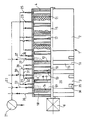
- the filter device comprises a cylindrical jacket 1, which is formed by two cylindrical jacket pieces 2, 3 and is closed at each end by an end wall 4.
- a shaft 5 runs through the housing formed by the casing 1 and the two end walls 4, which shaft can be driven by a motor 6 arranged outside the housing and carries rotor disks 7 arranged at a distance from one another in the housing, each with radial flow ribs on both ends 8 are provided.
- a seal 9 runs around the circumference of each tubular disk 7 with respect to the casing 1, so that liquid cannot pass through the rotor disk in the axial direction.
- a stator 10 is arranged on both sides of each rotor disk in the housing, through which liquid can pass almost unhindered and on the side assigned to the rotor disk 7 a disk-shaped filter medium is attached.
- the shaft 5 is composed in a manner known per se from various pieces and can be pulled apart, after which the stators 10 with the filter means can be removed through large openings 15 in the jacket 1.
- the large openings 15 are closed by correspondingly large lids 16 or flaps and are provided in one jacket piece 2.
- One of the two end walls 4 is provided at a distance from the two outer stators 10, and a partition 17 is provided in the middle between two inner stators 10.
- Each partition 17 is rotatable by the shaft 5, but penetrates liquid-tight and does not allow any liquid to pass from one side to the other.
- Chambers are formed in the housing, which are delimited radially outwards by the jacket 1.
- Inside each chamber there is a stator 10 provided with filter medium, a cavity 18 for receiving filtrate, a cavity 19 for receiving filter material and a cavity 20 for receiving turbidity.
- the cavity 20 for taking up the sludge and the cavity 19 for taking up the filter material merge into one another completely without separation.
- Each chamber is delimited on the one hand by a rotor 7 and on the other hand by an end wall 4 or a partition 17.
- a liquid mixture loaded with solid particles is fed in parallel to an inlet 23 of the first three chambers (seen from the right) via a feed line 22.
- a solid particle filter cake 24 forms in the cavity 19 for receiving the filter material of each of these three chambers.
- the filter cake 24 can be removed by pulling off the jacket piece 2 in the axial direction by means of a piston-cylinder device, not shown.
- the liquid mixture cleaned of solid particles emerges through outlets 25 of the three chambers. These three outlets 25 are brought together and led to an inlet 26 of a fourth chamber, the cavity 19 of which is provided for filter material reception with an outwardly leading line 27 in which a valve 37 is provided.
- a first liquid dirt component collects in the cavity and is discharged via line 27.
- the fifth chamber is provided with an outwardly leading line 30 provided with valve 37 for a second liquid dirt component and has an outlet 31 for the liquid freed from the second dirt component.
- the outlet 31 is connected to an inlet 32 of a sixth chamber which has an outwardly leading, valve 37 provided line 33 for a third liquid dirt component and delivers more or less purified water at an outlet 34.
- Each cavity 19 for receiving filter material is assigned a small opening 35 in the jacket 1, namely in its fixed jacket piece 3, which is closed by a small cover 36 or a flap.
- a liquid mixture originating from a car wash is cleaned, from which solid particles, which are formed by sand, paint or fat, are first extracted.
- liquid dirt components such as oil, petrol, fats, salt mixtures and surfactants are filtered out.
- Filter media that can be used are manufactured by Pal and Milipor.
- the use of two or more parallel chambers for the retention of solid particles generally takes place and is due to the content of solid particles in the liquid mixture; however, it is also possible to work with only one chamber for the retention of solid particles.
- two stators 10 separated by a partition 17 are structurally combined to form a stator device which is divided in the middle by the partition.
- the pressure of the supplied liquid mixture also has an effect that the liquid also flows in via the inlets 26, 29 and 32. If the pressure is not sufficient for this, small pumps are interposed.
Landscapes
- Chemical Kinetics & Catalysis (AREA)
- Chemical & Material Sciences (AREA)
- Filtration Of Liquid (AREA)
- Centrifugal Separators (AREA)
- Infusion, Injection, And Reservoir Apparatuses (AREA)
- Fluid-Pressure Circuits (AREA)
- Separation Using Semi-Permeable Membranes (AREA)
- Filtering Of Dispersed Particles In Gases (AREA)
- Lubrication Details And Ventilation Of Internal Combustion Engines (AREA)
- Sampling And Sample Adjustment (AREA)
- Accessories For Mixers (AREA)
- Glass Compositions (AREA)
- Separation By Low-Temperature Treatments (AREA)
- External Artificial Organs (AREA)
- Treatment Of Liquids With Adsorbents In General (AREA)
- Percussion Or Vibration Massage (AREA)
- Control Of Motors That Do Not Use Commutators (AREA)
- Cyclones (AREA)
Priority Applications (1)
| Application Number | Priority Date | Filing Date | Title |
|---|---|---|---|
| AT89106607T ATE82149T1 (de) | 1988-04-21 | 1989-04-13 | Filtervorrichtung fuer eine fluessigkeitenmischung. |
Applications Claiming Priority (2)
| Application Number | Priority Date | Filing Date | Title |
|---|---|---|---|
| DE3813343 | 1988-04-21 | ||
| DE3813343A DE3813343C2 (de) | 1988-04-21 | 1988-04-21 | Rotorfiltervorrichtung für eine Flüssigkeitenmischung |
Publications (3)
| Publication Number | Publication Date |
|---|---|
| EP0338432A2 true EP0338432A2 (fr) | 1989-10-25 |
| EP0338432A3 EP0338432A3 (en) | 1989-11-29 |
| EP0338432B1 EP0338432B1 (fr) | 1992-11-11 |
Family
ID=6352501
Family Applications (1)
| Application Number | Title | Priority Date | Filing Date |
|---|---|---|---|
| EP89106607A Expired - Lifetime EP0338432B1 (fr) | 1988-04-21 | 1989-04-13 | Dispositif filtrant pour un mélange liquide |
Country Status (15)
| Country | Link |
|---|---|
| US (1) | US4935137A (fr) |
| EP (1) | EP0338432B1 (fr) |
| JP (1) | JPH0243910A (fr) |
| AT (1) | ATE82149T1 (fr) |
| AU (1) | AU612817B2 (fr) |
| DD (1) | DD280256A5 (fr) |
| DE (2) | DE3813343C2 (fr) |
| DK (1) | DK156489A (fr) |
| ES (1) | ES2035976T3 (fr) |
| FI (1) | FI88113C (fr) |
| GR (1) | GR3006377T3 (fr) |
| HU (1) | HU205275B (fr) |
| NO (1) | NO173432C (fr) |
| RU (1) | RU1834681C (fr) |
| ZA (1) | ZA892542B (fr) |
Cited By (1)
| Publication number | Priority date | Publication date | Assignee | Title |
|---|---|---|---|---|
| EP0370118B1 (fr) * | 1988-11-17 | 1993-10-20 | HERCO-CFF ChiralFlow Filtertechnik GmbH | Appareil de filtration pour l'épuration d'un liquide |
Families Citing this family (2)
| Publication number | Priority date | Publication date | Assignee | Title |
|---|---|---|---|---|
| AU643089B2 (en) * | 1991-02-15 | 1993-11-04 | Toa Medical Electronics Co., Ltd. | Apparatus for regulating liquid temperature |
| GB201718939D0 (en) * | 2017-11-16 | 2018-01-03 | Dynamic Extractions Ltd | Centrifuge apparatus |
Family Cites Families (6)
| Publication number | Priority date | Publication date | Assignee | Title |
|---|---|---|---|---|
| HU170029B (fr) * | 1973-05-18 | 1977-03-28 | ||
| US4066546A (en) * | 1974-10-25 | 1978-01-03 | Toshin Science Co., Ltd. | Continuous filtering process and an apparatus therefor |
| US3984317A (en) * | 1975-06-05 | 1976-10-05 | Artisan Industries Inc. | Apparatus and process for continuous concentration and washing of solids from a solids-containing fluid |
| DE2836866A1 (de) * | 1978-08-23 | 1980-03-13 | Dynofag Ag | Verfahren und einrichtung zum abtrennen von fluessigkeiten aus suspensionen |
| DE3426527C2 (de) * | 1984-07-18 | 1986-07-24 | Bauko Baukooperation Gmbh, Salzburg | Kammerfilterpresse |
| PL154844B1 (en) * | 1985-12-23 | 1991-09-30 | Filter press and its rotor |
-
1988
- 1988-04-21 DE DE3813343A patent/DE3813343C2/de not_active Expired - Fee Related
-
1989
- 1989-03-30 DK DK156489A patent/DK156489A/da not_active IP Right Cessation
- 1989-03-31 HU HU891616A patent/HU205275B/hu not_active IP Right Cessation
- 1989-04-04 DD DD89327247A patent/DD280256A5/de not_active IP Right Cessation
- 1989-04-04 FI FI891602A patent/FI88113C/fi not_active IP Right Cessation
- 1989-04-07 ZA ZA892542A patent/ZA892542B/xx unknown
- 1989-04-12 AU AU32761/89A patent/AU612817B2/en not_active Ceased
- 1989-04-13 ES ES198989106607T patent/ES2035976T3/es not_active Expired - Lifetime
- 1989-04-13 AT AT89106607T patent/ATE82149T1/de not_active IP Right Cessation
- 1989-04-13 EP EP89106607A patent/EP0338432B1/fr not_active Expired - Lifetime
- 1989-04-13 DE DE8989106607T patent/DE58902645D1/de not_active Expired - Fee Related
- 1989-04-18 NO NO891577A patent/NO173432C/no unknown
- 1989-04-20 RU SU894613904A patent/RU1834681C/ru active
- 1989-04-21 JP JP1100349A patent/JPH0243910A/ja active Pending
- 1989-04-26 US US07/343,218 patent/US4935137A/en not_active Expired - Fee Related
-
1992
- 1992-11-27 GR GR920402753T patent/GR3006377T3/el unknown
Cited By (2)
| Publication number | Priority date | Publication date | Assignee | Title |
|---|---|---|---|---|
| EP0370118B1 (fr) * | 1988-11-17 | 1993-10-20 | HERCO-CFF ChiralFlow Filtertechnik GmbH | Appareil de filtration pour l'épuration d'un liquide |
| US5474675A (en) * | 1988-11-17 | 1995-12-12 | Herco-Cff Chiralflow Filtertechnik Gmbh | Filter separator for separating a composite fluid |
Also Published As
| Publication number | Publication date |
|---|---|
| JPH0243910A (ja) | 1990-02-14 |
| EP0338432B1 (fr) | 1992-11-11 |
| NO891577L (no) | 1989-10-23 |
| RU1834681C (ru) | 1993-08-15 |
| DD280256A5 (de) | 1990-07-04 |
| ES2035976T3 (es) | 1993-05-01 |
| FI891602A0 (fi) | 1989-04-04 |
| DE58902645D1 (de) | 1992-12-17 |
| FI88113B (fi) | 1992-12-31 |
| DE3813343A1 (de) | 1989-11-09 |
| FI88113C (fi) | 1993-04-13 |
| DK156489D0 (da) | 1989-03-30 |
| AU612817B2 (en) | 1991-07-18 |
| DE3813343C2 (de) | 1994-11-17 |
| EP0338432A3 (en) | 1989-11-29 |
| NO891577D0 (no) | 1989-04-18 |
| HUT52984A (en) | 1990-09-28 |
| NO173432B (no) | 1993-09-06 |
| HU205275B (en) | 1992-04-28 |
| ATE82149T1 (de) | 1992-11-15 |
| FI891602A7 (fi) | 1989-10-22 |
| NO173432C (no) | 1993-12-15 |
| ZA892542B (en) | 1989-12-27 |
| US4935137A (en) | 1990-06-19 |
| GR3006377T3 (fr) | 1993-06-21 |
| AU3276189A (en) | 1989-10-26 |
| DK156489A (da) | 1989-10-22 |
Similar Documents
| Publication | Publication Date | Title |
|---|---|---|
| EP1286743B1 (fr) | Filtre a lavage a contre-courant, notamment destine a la filtration d'huile lubrifiante | |
| EP1740287A1 (fr) | Filtre a carburant | |
| EP0577854B1 (fr) | Dispositif de filtration | |
| WO1988005335A2 (fr) | Appareil de filtration pour filtrer des liquides contamines | |
| DE1241802B (de) | Filterapparat | |
| DE3103842A1 (de) | Wirbelkammerfilter zum ausscheiden von feststoffen aus einem gasstrom | |
| EP0024514A1 (fr) | Dispositif filtrant pour la filtration de liquides, en particulier d'huile de graissage | |
| DE2728137A1 (de) | Siebfilter fuer industriewasser | |
| DE2327532C3 (de) | Flüssigkeitsfilter mit selbsttätiger Reinigung | |
| DE1007743B (de) | Filter fuer Fluessigkeiten | |
| EP0338432B1 (fr) | Dispositif filtrant pour un mélange liquide | |
| DE10243122A1 (de) | Selbstreinigende Filteranordnung | |
| DE69002614T2 (de) | Trennschleuder. | |
| DE817443C (de) | Verdampfer | |
| DE2434943A1 (de) | Vorrichtung zur entfernung von fluessigkeit aus einer suspension | |
| DE2724449A1 (de) | Zentrifuge, insbesondere vollmantel- schneckenzentrifuge, zur trennung der festen phase von der fluessigen phase eines feststoff-fluessigkeitsgemisches | |
| DE3341281A1 (de) | Fluessigkeitsfilter | |
| DE3233523A1 (de) | Oelfilter | |
| DE2660630C2 (de) | Hohlfaserdialysator | |
| DE29518534U1 (de) | Filter zum kontinuierlichen Filtern von Feststoffe aufweisenden Flüssigkeiten | |
| DE3711114A1 (de) | Brauchwasserrueckspuelfilter | |
| DE1486818C3 (de) | Hochdruckfiltervorrichtung | |
| DE713098C (de) | Schmieroelfilter fuer Hochleistungsbrennkraftmaschinen | |
| DE3117777A1 (de) | Filtervorrichtung zur abtrennung von festkoerperteilchen aus fluessigkeiten | |
| DE102023121268A1 (de) | Mikroplastikfilter für eine Haushaltsmaschine und Filtergehäuse für den Mikroplastikfilter |
Legal Events
| Date | Code | Title | Description |
|---|---|---|---|
| PUAI | Public reference made under article 153(3) epc to a published international application that has entered the european phase |
Free format text: ORIGINAL CODE: 0009012 |
|
| PUAL | Search report despatched |
Free format text: ORIGINAL CODE: 0009013 |
|
| AK | Designated contracting states |
Kind code of ref document: A2 Designated state(s): AT BE CH DE ES FR GB GR IT LI LU NL SE |
|
| AK | Designated contracting states |
Kind code of ref document: A3 Designated state(s): AT BE CH DE ES FR GB GR IT LI LU NL SE |
|
| 17P | Request for examination filed |
Effective date: 19900511 |
|
| 17Q | First examination report despatched |
Effective date: 19911017 |
|
| GRAA | (expected) grant |
Free format text: ORIGINAL CODE: 0009210 |
|
| AK | Designated contracting states |
Kind code of ref document: B1 Designated state(s): AT BE CH DE ES FR GB GR IT LI LU NL SE |
|
| REF | Corresponds to: |
Ref document number: 82149 Country of ref document: AT Date of ref document: 19921115 Kind code of ref document: T |
|
| REF | Corresponds to: |
Ref document number: 58902645 Country of ref document: DE Date of ref document: 19921217 |
|
| GBT | Gb: translation of ep patent filed (gb section 77(6)(a)/1977) |
Effective date: 19921202 |
|
| ITF | It: translation for a ep patent filed | ||
| ET | Fr: translation filed | ||
| REG | Reference to a national code |
Ref country code: GR Ref legal event code: FG4A Free format text: 3006377 |
|
| REG | Reference to a national code |
Ref country code: ES Ref legal event code: FG2A Ref document number: 2035976 Country of ref document: ES Kind code of ref document: T3 |
|
| PLBE | No opposition filed within time limit |
Free format text: ORIGINAL CODE: 0009261 |
|
| STAA | Information on the status of an ep patent application or granted ep patent |
Free format text: STATUS: NO OPPOSITION FILED WITHIN TIME LIMIT |
|
| 26N | No opposition filed | ||
| EPTA | Lu: last paid annual fee | ||
| EAL | Se: european patent in force in sweden |
Ref document number: 89106607.8 |
|
| PGFP | Annual fee paid to national office [announced via postgrant information from national office to epo] |
Ref country code: GB Payment date: 19950327 Year of fee payment: 7 |
|
| PGFP | Annual fee paid to national office [announced via postgrant information from national office to epo] |
Ref country code: LU Payment date: 19950401 Year of fee payment: 7 |
|
| PGFP | Annual fee paid to national office [announced via postgrant information from national office to epo] |
Ref country code: FR Payment date: 19950413 Year of fee payment: 7 |
|
| PGFP | Annual fee paid to national office [announced via postgrant information from national office to epo] |
Ref country code: AT Payment date: 19950420 Year of fee payment: 7 |
|
| PGFP | Annual fee paid to national office [announced via postgrant information from national office to epo] |
Ref country code: SE Payment date: 19950421 Year of fee payment: 7 |
|
| PGFP | Annual fee paid to national office [announced via postgrant information from national office to epo] |
Ref country code: GR Payment date: 19950428 Year of fee payment: 7 Ref country code: ES Payment date: 19950428 Year of fee payment: 7 |
|
| PGFP | Annual fee paid to national office [announced via postgrant information from national office to epo] |
Ref country code: NL Payment date: 19950430 Year of fee payment: 7 |
|
| PGFP | Annual fee paid to national office [announced via postgrant information from national office to epo] |
Ref country code: BE Payment date: 19950510 Year of fee payment: 7 |
|
| PGFP | Annual fee paid to national office [announced via postgrant information from national office to epo] |
Ref country code: DE Payment date: 19950512 Year of fee payment: 7 |
|
| PGFP | Annual fee paid to national office [announced via postgrant information from national office to epo] |
Ref country code: CH Payment date: 19950519 Year of fee payment: 7 |
|
| PG25 | Lapsed in a contracting state [announced via postgrant information from national office to epo] |
Ref country code: LU Free format text: LAPSE BECAUSE OF NON-PAYMENT OF DUE FEES Effective date: 19960413 Ref country code: GB Effective date: 19960413 Ref country code: AT Effective date: 19960413 |
|
| PG25 | Lapsed in a contracting state [announced via postgrant information from national office to epo] |
Ref country code: SE Effective date: 19960414 |
|
| PG25 | Lapsed in a contracting state [announced via postgrant information from national office to epo] |
Ref country code: ES Free format text: LAPSE BECAUSE OF NON-PAYMENT OF DUE FEES Effective date: 19960415 |
|
| PG25 | Lapsed in a contracting state [announced via postgrant information from national office to epo] |
Ref country code: LI Effective date: 19960430 Ref country code: CH Effective date: 19960430 Ref country code: BE Effective date: 19960430 |
|
| BERE | Be: lapsed |
Owner name: APPARATEBAU BIERSDORF WALTER KRAMER G.M.B.H. RAIN Effective date: 19960430 |
|
| PG25 | Lapsed in a contracting state [announced via postgrant information from national office to epo] |
Ref country code: GR Free format text: THE PATENT HAS BEEN ANNULLED BY A DECISION OF A NATIONAL AUTHORITY Effective date: 19961031 |
|
| PG25 | Lapsed in a contracting state [announced via postgrant information from national office to epo] |
Ref country code: NL Effective date: 19961101 |
|
| REG | Reference to a national code |
Ref country code: GR Ref legal event code: MM2A Free format text: 3006377 |
|
| GBPC | Gb: european patent ceased through non-payment of renewal fee |
Effective date: 19960413 |
|
| REG | Reference to a national code |
Ref country code: CH Ref legal event code: PL |
|
| PG25 | Lapsed in a contracting state [announced via postgrant information from national office to epo] |
Ref country code: FR Effective date: 19961227 |
|
| PG25 | Lapsed in a contracting state [announced via postgrant information from national office to epo] |
Ref country code: DE Effective date: 19970101 |
|
| NLV4 | Nl: lapsed or anulled due to non-payment of the annual fee |
Effective date: 19961101 |
|
| EUG | Se: european patent has lapsed |
Ref document number: 89106607.8 |
|
| REG | Reference to a national code |
Ref country code: FR Ref legal event code: ST |
|
| REG | Reference to a national code |
Ref country code: ES Ref legal event code: FD2A Effective date: 19990405 |
|
| PG25 | Lapsed in a contracting state [announced via postgrant information from national office to epo] |
Ref country code: IT Free format text: LAPSE BECAUSE OF NON-PAYMENT OF DUE FEES;WARNING: LAPSES OF ITALIAN PATENTS WITH EFFECTIVE DATE BEFORE 2007 MAY HAVE OCCURRED AT ANY TIME BEFORE 2007. THE CORRECT EFFECTIVE DATE MAY BE DIFFERENT FROM THE ONE RECORDED. Effective date: 20050413 |