EP0338471A2 - Unterteilende Kaskadenschaltung für eine Zwischenstation in einem Radio-Telefonnetzwerk - Google Patents
Unterteilende Kaskadenschaltung für eine Zwischenstation in einem Radio-Telefonnetzwerk Download PDFInfo
- Publication number
- EP0338471A2 EP0338471A2 EP89106804A EP89106804A EP0338471A2 EP 0338471 A2 EP0338471 A2 EP 0338471A2 EP 89106804 A EP89106804 A EP 89106804A EP 89106804 A EP89106804 A EP 89106804A EP 0338471 A2 EP0338471 A2 EP 0338471A2
- Authority
- EP
- European Patent Office
- Prior art keywords
- dividing
- cascade
- network
- dividing network
- coupling
- Prior art date
- Legal status (The legal status is an assumption and is not a legal conclusion. Google has not performed a legal analysis and makes no representation as to the accuracy of the status listed.)
- Granted
Links
Images

Classifications
-
- H—ELECTRICITY
- H03—ELECTRONIC CIRCUITRY
- H03H—IMPEDANCE NETWORKS, e.g. RESONANT CIRCUITS; RESONATORS
- H03H7/00—Multiple-port networks comprising only passive electrical elements as network components
- H03H7/46—Networks for connecting several sources or loads, working on different frequencies or frequency bands, to a common load or source
Definitions
- the invention relates to a dividing network in the support station in a radio telephone network, wherein a received multi-channel antenna signal is divided among separate receivers by means of a dividing unit, the dividing unit consisting of a filter, an amplifier and a dividing network.
- the support stations comprise a plurality of frequency channels, which may be time channeled and/or frequency channeled. Owing to limited antenna space and to cabling costs, the aim is to connect several parallel receivers and transmitters to the same antenna.
- receiver or reception used hereinafter is to be understood as also meaning transmission or a transmitter.
- a multi-channel reception can be implemented by using a socalled dividing unit. All of the connections of the dividing unit must be well matched within the entire reception band, and faults in individual receivers must not disturb the other receivers in operation.
- the dividing unit must be easy to extend and also small in size.
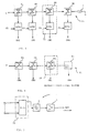
- Figure 1 shows a typical prior-art block diagram of such a dividing network.
- the dividing unit is made up of a filter 2, an amplifier 3, and the actual dividing network 1 which divides the antenna signal.
- the multi-channel antenna signal ANT arrives, filtered and amplified, at the dividing network 1 at point 4.
- the dividing network 1 is typically made up of several parallel passive dividers, dividing by three or the like; by means of these dividers the received signals are divided equally among the separate receivers, outputs CH1, CH2-CHn. For extension of the dividing network, one unused output EXT is often left in the network.
- Figure 2 illustrates the structure of the dividing network in this prior-art system.
- the problem involved in the dividing unit described is how to implement the dividing so that the result will be a small-sized system requiring little external cabling.
- the extension of the network may also involve problems, as may electrical deficiencies in it, such as weak output matchings and possibly limited insulation between the outputs.
- the object of the invention is therefore to find a dividing network structure by means of which the disadvantages of prior-art technology are avoided and which also facilitates the manufacture of the equipment and the assembly planning and cabling of the system.
- the dividing network has N directional couplers in a cascade, there being branched out from the cascade successivelysively to each of N receivers a share, in accordance with the coupling of the directional coupler, of the filtered and amplified antenna signal.
- N directional couplers in connection with a transmitter, it has, in a cascade, N directional couplers, there being coupled to this cascade from each of N transmitters a share, according to the coupling of the directional coupler, of the filtered and amplified antenna signal.
- Figure 3 depicts a cascade dividing network according to the invention, and one embodiment of it, as a block diagram.
- a filtered and amplified multi-channel antenna signal 4 is led to matched directional couplers H1-Hn, by means of which the signals coming to receivers CH1-CHn of the channel units are branched.
- the receivers can be connected either directly or via controllable attenuators ATT1-ATTn.
- the cascade is terminated in an impedance I. In this embodiment the couplings k of the directional couplers are always equal.
- the signal level is attenuated after each directional coupler so that, after the i th output, the level has been attenuated:
- a (output i) 10*(L-1)*log10(1-10 k/10 )+k dB as compared with input 4.
- the signal level is different in each output of the dividing network.
- the different values of the output-specific attenuations, i.e. in practice the signal levels, can be compensated for either by means of controllable attenuators ATT1-ATTn or by taking into account, when measuring the strength differences of the field, the attenuation difference in the receivers coupled to the dividing unit.
- the supplementary attenuation required when using controllable attenuators can easily be measured automatically when the support station is in the so-called RF-loop state judged on the basis of the strength reading of the field.
- the control can be summated by using, for example, voltage-controlled PIN diode attenuators.
- the controls are indicated by reference numerals C1-Cn.
- the directional couplers H1-Hn of the dividing network 11 may be separate or be disposed directly in connection with the receivers inside the channel units, in which case it will be easy to attain a large electrical resolution between the directional couplers.
- the directional couplers H1-Hn are identical, in which case their design and implementation even in large production runs is inexpensive and precise.
- the cascade dividing network 11 according to Figure 3 can, of course, be applied for use also in connection with a transmitter or transmitters; this situation is depicted schematically in Figure 5.
- the cascade dividing network according to the invention can also be implemented in a variable-coupling form.
- the couplings of the directional couplers B1-Bn are not equal ( Figure 4).
- k1 ⁇ k2 ⁇ ...ki... ⁇ kn is in force.
- the special features of this second embodiment example include, not only the above-mentioned absence of the n th directional coupler, but also the fact that channel-specific controllable attenuators are not at all necessary.
- the directional couplers can be implemented as separate couplers directly inside the channel units, which is indicated by unit 23, depicted by broken line. Also in this case a high electrical resolution can be simply achieved between the directional couplers.
- the cabling in the construction of the support station can be implemented in a simple form.
- the dividing network according to Figure 4 can be used in connection with a transmitter, for example in block 31 (in Figure 5).
- the cascade dividing networks according to the invention can be used most advantageously in multi-channel diversity support stations having more than 16 channels.
- the dividing network can be implemented within the channel units CH1-CHn.
- the preferred embodiment provides for a very simple antenna cabling between the channels and for good possibilities for extending the dividing network. In its electrical proper nonethelessties the cascade dividing network is easier to implement in accordance with the requirements than is a dividing network in accordance with the state of the art.
- FIG. 5 shows schematically the use of a dividing network according to the invention in a transmitter system.
- signals coming from separate transmitters T1-Tn are fed to the dividing network 31, from which they are fed via the filter 2 to the amplifier 3 in order to be fed further as a multi-channel antenna signal to the antenna ANT.
- the dividing network can be implemented either in a constant-coupling or variable-coupling form in accordance with the embodiment examples described above. In practice, however, the dividing networks used in transmitter coupling are such that the carrier-wave specific power levels must remain low in order that the total power loss should not be high.
- Uses for the dividing network according to the present invention are found particularly at support stations of cellular telephone systems.
Landscapes
- Mobile Radio Communication Systems (AREA)
- Vessels, Lead-In Wires, Accessory Apparatuses For Cathode-Ray Tubes (AREA)
- Magnetic Ceramics (AREA)
- Variable-Direction Aerials And Aerial Arrays (AREA)
- Input Circuits Of Receivers And Coupling Of Receivers And Audio Equipment (AREA)
- Transceivers (AREA)
Applications Claiming Priority (2)
| Application Number | Priority Date | Filing Date | Title |
|---|---|---|---|
| FI881813 | 1988-04-18 | ||
| FI881813A FI79210C (fi) | 1988-04-18 | 1988-04-18 | Foergreningsnaet i kedja foer en basstation i ett radiotelefonnaet. |
Publications (3)
| Publication Number | Publication Date |
|---|---|
| EP0338471A2 true EP0338471A2 (de) | 1989-10-25 |
| EP0338471A3 EP0338471A3 (en) | 1990-09-12 |
| EP0338471B1 EP0338471B1 (de) | 1996-08-14 |
Family
ID=8526307
Family Applications (1)
| Application Number | Title | Priority Date | Filing Date |
|---|---|---|---|
| EP89106804A Expired - Lifetime EP0338471B1 (de) | 1988-04-18 | 1989-04-17 | Unterteilende Kaskadenschaltung für eine Zwischenstation in einem Radio-Telefonnetzwerk |
Country Status (5)
| Country | Link |
|---|---|
| US (1) | US4998078A (de) |
| EP (1) | EP0338471B1 (de) |
| AT (1) | ATE141450T1 (de) |
| DE (1) | DE68926926T2 (de) |
| FI (1) | FI79210C (de) |
Families Citing this family (28)
| Publication number | Priority date | Publication date | Assignee | Title |
|---|---|---|---|---|
| US6111545A (en) * | 1992-01-23 | 2000-08-29 | Nokia Mobile Phones, Ltd. | Antenna |
| US6008765A (en) * | 1994-12-23 | 1999-12-28 | Nokia Mobile Phones Limited | Retractable top load antenna |
| FI99219C (fi) * | 1995-06-06 | 1997-10-27 | Nokia Mobile Phones Ltd | Kahdella taajuusalueella toimiva antenni |
| GB2303968B (en) * | 1995-08-03 | 1999-11-10 | Nokia Mobile Phones Ltd | Antenna |
| GB2305505B (en) * | 1995-09-25 | 2000-02-23 | Nokia Mobile Phones Ltd | Antenna assembly for a radio transceiver |
| GB2306056B (en) * | 1995-10-06 | 1999-12-08 | Nokia Mobile Phones Ltd | Antenna |
| FI955125A7 (fi) * | 1995-10-27 | 1997-04-28 | Nokia Corp | Antennin liitäntä |
| DE69532502T2 (de) * | 1995-11-08 | 2004-11-04 | Nokia Corp. | Funksendeempfänger |
| GB2308013B (en) * | 1995-12-07 | 1999-05-12 | Nokia Mobile Phones Ltd | A radio device |
| US5887262A (en) * | 1996-04-19 | 1999-03-23 | Nokia Mobile Phones Limited | Smart antenna backwards compatibility in digital cellular systems |
| US5854970A (en) * | 1996-10-08 | 1998-12-29 | Nokia Mobile Phones Limited | Accessory RF unit for hand-held wireless telephone systems |
| GB2320815B (en) * | 1996-12-23 | 2001-12-12 | Nokia Mobile Phones Ltd | Antenna assembly |
| DE19705735A1 (de) * | 1997-02-14 | 1998-08-20 | Nokia Mobile Phones Ltd | Verfahren und Vorrichtung zur Inspektion wenigstens eines Antennenzweigs, insbesondere in einem Fahrzeug |
| US5898406A (en) * | 1997-03-13 | 1999-04-27 | Nokia Mobile Phones Limited | Antenna mounted diplexer |
| FI110395B (fi) * | 1997-03-25 | 2003-01-15 | Nokia Corp | Oikosuljetuilla mikroliuskoilla toteutettu laajakaista-antenni |
| FI112723B (fi) * | 1997-03-27 | 2003-12-31 | Nokia Corp | Langattomien viestimien antenni |
| FI104662B (fi) * | 1997-04-11 | 2000-04-14 | Nokia Mobile Phones Ltd | Antennijärjestely pienikokoisiin radioviestintä-laitteisiin |
| GB2325089B (en) | 1997-05-09 | 2002-02-27 | Nokia Mobile Phones Ltd | Portable radio telephone |
| GB2325109B (en) | 1997-05-09 | 2001-08-22 | Nokia Mobile Phones Ltd | Portable radio telephone |
| FI113212B (fi) * | 1997-07-08 | 2004-03-15 | Nokia Corp | Usean taajuusalueen kaksoisresonanssiantennirakenne |
| GB2330951B (en) * | 1997-11-04 | 2002-09-18 | Nokia Mobile Phones Ltd | Antenna |
| FI974350A7 (fi) | 1997-11-27 | 1999-05-28 | Nokia Corp | Monilankaiset helix-antennit matkaviestinlaitteita varten |
| FI113814B (fi) | 1997-11-27 | 2004-06-15 | Nokia Corp | Monilankaiset helix-antennit |
| US6028567A (en) * | 1997-12-10 | 2000-02-22 | Nokia Mobile Phones, Ltd. | Antenna for a mobile station operating in two frequency ranges |
| GB2332780A (en) * | 1997-12-22 | 1999-06-30 | Nokia Mobile Phones Ltd | Flat plate antenna |
| FI980300L (fi) | 1998-02-10 | 1999-08-11 | Nokia Mobile Phones Ltd | Korttimainen langaton viestin |
| US8363744B2 (en) | 2001-06-10 | 2013-01-29 | Aloft Media, Llc | Method and system for robust, secure, and high-efficiency voice and packet transmission over ad-hoc, mesh, and MIMO communication networks |
| US7317902B2 (en) * | 2001-06-28 | 2008-01-08 | Harris Corporation | Successive log video pad power detector and method |
Family Cites Families (6)
| Publication number | Priority date | Publication date | Assignee | Title |
|---|---|---|---|---|
| US2775740A (en) * | 1950-11-02 | 1956-12-25 | Bell Telephone Labor Inc | Directional coupling systems |
| NL297915A (de) * | 1962-09-17 | |||
| US3453638A (en) * | 1966-03-22 | 1969-07-01 | Communications Inc | Multiplex package |
| FR1548848A (de) * | 1967-01-13 | 1968-12-06 | ||
| DE2213962C3 (de) * | 1972-03-22 | 1979-01-18 | Siemens Ag, 1000 Berlin Und 8000 Muenchen | Funkfeld in einem Richtfunksystem |
| DE3226728A1 (de) * | 1982-07-16 | 1984-01-19 | ANT Nachrichtentechnik GmbH, 7150 Backnang | Mikrowellen-weichenanordnung mit sender- bzw. empfaengerersatzschaltung |
-
1988
- 1988-04-18 FI FI881813A patent/FI79210C/fi not_active IP Right Cessation
-
1989
- 1989-04-11 US US07/336,259 patent/US4998078A/en not_active Expired - Lifetime
- 1989-04-17 DE DE68926926T patent/DE68926926T2/de not_active Expired - Lifetime
- 1989-04-17 AT AT89106804T patent/ATE141450T1/de not_active IP Right Cessation
- 1989-04-17 EP EP89106804A patent/EP0338471B1/de not_active Expired - Lifetime
Also Published As
| Publication number | Publication date |
|---|---|
| ATE141450T1 (de) | 1996-08-15 |
| EP0338471A3 (en) | 1990-09-12 |
| DE68926926T2 (de) | 1997-01-30 |
| FI79210C (fi) | 1989-11-10 |
| EP0338471B1 (de) | 1996-08-14 |
| DE68926926D1 (de) | 1996-09-19 |
| FI79210B (fi) | 1989-07-31 |
| US4998078A (en) | 1991-03-05 |
| FI881813A0 (fi) | 1988-04-18 |
Similar Documents
| Publication | Publication Date | Title |
|---|---|---|
| EP0338471B1 (de) | Unterteilende Kaskadenschaltung für eine Zwischenstation in einem Radio-Telefonnetzwerk | |
| US5175878A (en) | Radio network with switching arrangement for coupling radios to a selected antenna out of a plurality of antennas | |
| EP2433377B2 (de) | System zur verteilung von funkfrequenzsignalen | |
| EP0538635A2 (de) | Mikrozellenmobilkommunikationssystem | |
| AU770637B2 (en) | A radio transceiver and a method of preventing transmission spurious response | |
| SE429280B (sv) | Flerkanaligt sendarsystem for ett mobilt kommunikationssystem | |
| US10374687B2 (en) | Base station signal matching device and relay device including the same | |
| US9048931B2 (en) | Method and arrangement for feeder sharing in a telecommunication system | |
| US4159454A (en) | Plug-in filter network for separating a communication frequency into discrete frequency channels | |
| CN113612545A (zh) | 开关矩阵和测试系统 | |
| EP0046741A2 (de) | Hochleistungsmultiplexer für Erdfunkstellen mit Doppelpolarisation und Frequenzwiederverwertung | |
| US3816835A (en) | Multiplexer-demultiplexer for microwave antennas | |
| CN114339486B (zh) | 一种时频信号的光纤网络分配与传输方法 | |
| US5859854A (en) | System and method for frequency multiplexing antenna signals | |
| US5239690A (en) | Hand-held transceiver as a modular unit | |
| CA2035390A1 (en) | Cellular mobile radio system | |
| AU718633B2 (en) | Multi-branch frequency-hopping receiver | |
| CN215498936U (zh) | 一种变频接收装置 | |
| GB2279504A (en) | Antenna system | |
| EP0271347A2 (de) | Anordnung von Funksendern | |
| US4135193A (en) | Directional duplexer | |
| US7486968B2 (en) | Method and system for transmission of carrier signals between first and second antenna networks | |
| ITBO20000634A1 (it) | Rete di comunicazione, in particolare per telefonia | |
| US11204380B2 (en) | Module tuning using virtual gain correction | |
| KR200153043Y1 (ko) | 하이-q 유전체 필터를 이용한 콤바이너 |
Legal Events
| Date | Code | Title | Description |
|---|---|---|---|
| PUAI | Public reference made under article 153(3) epc to a published international application that has entered the european phase |
Free format text: ORIGINAL CODE: 0009012 |
|
| AK | Designated contracting states |
Kind code of ref document: A2 Designated state(s): AT BE CH DE ES FR GB GR IT LI LU NL SE |
|
| PUAL | Search report despatched |
Free format text: ORIGINAL CODE: 0009013 |
|
| AK | Designated contracting states |
Kind code of ref document: A3 Designated state(s): AT BE CH DE ES FR GB GR IT LI LU NL SE |
|
| 17P | Request for examination filed |
Effective date: 19901107 |
|
| RAP1 | Party data changed (applicant data changed or rights of an application transferred) |
Owner name: NOKIA MOBILE PHONES LTD. |
|
| 17Q | First examination report despatched |
Effective date: 19930611 |
|
| GRAH | Despatch of communication of intention to grant a patent |
Free format text: ORIGINAL CODE: EPIDOS IGRA |
|
| GRAA | (expected) grant |
Free format text: ORIGINAL CODE: 0009210 |
|
| AK | Designated contracting states |
Kind code of ref document: B1 Designated state(s): AT BE CH DE ES FR GB GR IT LI LU NL SE |
|
| PG25 | Lapsed in a contracting state [announced via postgrant information from national office to epo] |
Ref country code: IT Free format text: LAPSE BECAUSE OF FAILURE TO SUBMIT A TRANSLATION OF THE DESCRIPTION OR TO PAY THE FEE WITHIN THE PRE;WARNING: LAPSES OF ITALIAN PATENTS WITH EFFECTIVE DATE BEFORE 2007 MAY HAVE OCCURRED AT ANY TIME BEFORE 2007. THE CORRECT EFFECTIVE DATE MAY BE DIFFERENT FROM THE ONE RECORDED.SCRIBED TIME-LIMIT Effective date: 19960814 Ref country code: AT Effective date: 19960814 Ref country code: LI Effective date: 19960814 Ref country code: GR Free format text: LAPSE BECAUSE OF FAILURE TO SUBMIT A TRANSLATION OF THE DESCRIPTION OR TO PAY THE FEE WITHIN THE PRESCRIBED TIME-LIMIT Effective date: 19960814 Ref country code: NL Free format text: LAPSE BECAUSE OF FAILURE TO SUBMIT A TRANSLATION OF THE DESCRIPTION OR TO PAY THE FEE WITHIN THE PRESCRIBED TIME-LIMIT Effective date: 19960814 Ref country code: BE Effective date: 19960814 Ref country code: CH Effective date: 19960814 Ref country code: ES Free format text: THE PATENT HAS BEEN ANNULLED BY A DECISION OF A NATIONAL AUTHORITY Effective date: 19960814 |
|
| REF | Corresponds to: |
Ref document number: 141450 Country of ref document: AT Date of ref document: 19960815 Kind code of ref document: T |
|
| REF | Corresponds to: |
Ref document number: 68926926 Country of ref document: DE Date of ref document: 19960919 |
|
| ET | Fr: translation filed | ||
| NLV1 | Nl: lapsed or annulled due to failure to fulfill the requirements of art. 29p and 29m of the patents act | ||
| REG | Reference to a national code |
Ref country code: CH Ref legal event code: PL |
|
| PG25 | Lapsed in a contracting state [announced via postgrant information from national office to epo] |
Ref country code: LU Free format text: LAPSE BECAUSE OF NON-PAYMENT OF DUE FEES Effective date: 19970430 |
|
| PLBE | No opposition filed within time limit |
Free format text: ORIGINAL CODE: 0009261 |
|
| STAA | Information on the status of an ep patent application or granted ep patent |
Free format text: STATUS: NO OPPOSITION FILED WITHIN TIME LIMIT |
|
| 26N | No opposition filed | ||
| REG | Reference to a national code |
Ref country code: GB Ref legal event code: IF02 |
|
| REG | Reference to a national code |
Ref country code: GB Ref legal event code: 732E |
|
| PGFP | Annual fee paid to national office [announced via postgrant information from national office to epo] |
Ref country code: SE Payment date: 20040406 Year of fee payment: 16 |
|
| PG25 | Lapsed in a contracting state [announced via postgrant information from national office to epo] |
Ref country code: SE Free format text: LAPSE BECAUSE OF NON-PAYMENT OF DUE FEES Effective date: 20050418 |
|
| EUG | Se: european patent has lapsed | ||
| PGFP | Annual fee paid to national office [announced via postgrant information from national office to epo] |
Ref country code: FR Payment date: 20080312 Year of fee payment: 20 Ref country code: DE Payment date: 20080424 Year of fee payment: 20 |
|
| PGFP | Annual fee paid to national office [announced via postgrant information from national office to epo] |
Ref country code: GB Payment date: 20080423 Year of fee payment: 20 |
|
| REG | Reference to a national code |
Ref country code: GB Ref legal event code: PE20 Expiry date: 20090416 |
|
| PG25 | Lapsed in a contracting state [announced via postgrant information from national office to epo] |
Ref country code: GB Free format text: LAPSE BECAUSE OF EXPIRATION OF PROTECTION Effective date: 20090416 |