EP0338624A1 - Gerät mittels magnetischer Resonanz mit entkoppelten HF-Spulen - Google Patents
Gerät mittels magnetischer Resonanz mit entkoppelten HF-Spulen Download PDFInfo
- Publication number
- EP0338624A1 EP0338624A1 EP89200951A EP89200951A EP0338624A1 EP 0338624 A1 EP0338624 A1 EP 0338624A1 EP 89200951 A EP89200951 A EP 89200951A EP 89200951 A EP89200951 A EP 89200951A EP 0338624 A1 EP0338624 A1 EP 0338624A1
- Authority
- EP
- European Patent Office
- Prior art keywords
- coils
- magnetic resonance
- coil
- overlap
- resonance apparatus
- Prior art date
- Legal status (The legal status is an assumption and is not a legal conclusion. Google has not performed a legal analysis and makes no representation as to the accuracy of the status listed.)
- Withdrawn
Links
- 238000001514 detection method Methods 0.000 claims abstract description 6
- 239000004020 conductor Substances 0.000 claims description 5
- 230000008878 coupling Effects 0.000 claims description 5
- 238000010168 coupling process Methods 0.000 claims description 5
- 238000005859 coupling reaction Methods 0.000 claims description 5
- 238000005259 measurement Methods 0.000 abstract description 13
- 230000001627 detrimental effect Effects 0.000 abstract 1
- 230000004907 flux Effects 0.000 abstract 1
- 238000001816 cooling Methods 0.000 description 4
- IJGRMHOSHXDMSA-UHFFFAOYSA-N Atomic nitrogen Chemical compound N#N IJGRMHOSHXDMSA-UHFFFAOYSA-N 0.000 description 2
- 230000006698 induction Effects 0.000 description 2
- 238000000691 measurement method Methods 0.000 description 2
- 238000000034 method Methods 0.000 description 2
- RYGMFSIKBFXOCR-UHFFFAOYSA-N Copper Chemical compound [Cu] RYGMFSIKBFXOCR-UHFFFAOYSA-N 0.000 description 1
- 230000002411 adverse Effects 0.000 description 1
- 230000003321 amplification Effects 0.000 description 1
- 230000005540 biological transmission Effects 0.000 description 1
- 230000015572 biosynthetic process Effects 0.000 description 1
- 229910052802 copper Inorganic materials 0.000 description 1
- 239000010949 copper Substances 0.000 description 1
- 238000006073 displacement reaction Methods 0.000 description 1
- 230000002349 favourable effect Effects 0.000 description 1
- 239000001307 helium Substances 0.000 description 1
- 229910052734 helium Inorganic materials 0.000 description 1
- SWQJXJOGLNCZEY-UHFFFAOYSA-N helium atom Chemical compound [He] SWQJXJOGLNCZEY-UHFFFAOYSA-N 0.000 description 1
- 239000007788 liquid Substances 0.000 description 1
- 229910052757 nitrogen Inorganic materials 0.000 description 1
- 238000003199 nucleic acid amplification method Methods 0.000 description 1
- 230000001360 synchronised effect Effects 0.000 description 1
- XLYOFNOQVPJJNP-UHFFFAOYSA-N water Substances O XLYOFNOQVPJJNP-UHFFFAOYSA-N 0.000 description 1
Images
Classifications
-
- G—PHYSICS
- G01—MEASURING; TESTING
- G01R—MEASURING ELECTRIC VARIABLES; MEASURING MAGNETIC VARIABLES
- G01R33/00—Arrangements or instruments for measuring magnetic variables
- G01R33/20—Arrangements or instruments for measuring magnetic variables involving magnetic resonance
- G01R33/28—Details of apparatus provided for in groups G01R33/44 - G01R33/64
- G01R33/32—Excitation or detection systems, e.g. using radio frequency signals
- G01R33/34—Constructional details, e.g. resonators, specially adapted to MR
- G01R33/341—Constructional details, e.g. resonators, specially adapted to MR comprising surface coils
-
- G—PHYSICS
- G01—MEASURING; TESTING
- G01R—MEASURING ELECTRIC VARIABLES; MEASURING MAGNETIC VARIABLES
- G01R33/00—Arrangements or instruments for measuring magnetic variables
- G01R33/20—Arrangements or instruments for measuring magnetic variables involving magnetic resonance
- G01R33/28—Details of apparatus provided for in groups G01R33/44 - G01R33/64
- G01R33/32—Excitation or detection systems, e.g. using radio frequency signals
- G01R33/34—Constructional details, e.g. resonators, specially adapted to MR
- G01R33/341—Constructional details, e.g. resonators, specially adapted to MR comprising surface coils
- G01R33/3415—Constructional details, e.g. resonators, specially adapted to MR comprising surface coils comprising arrays of sub-coils, i.e. phased-array coils with flexible receiver channels
Definitions
- the invention relates to a magnetic resonance apparatus having a magnet system for generating a steady magnetic field, a coil system for generating gradient fields, an rf transmitter coil and an rf coil system with coils overlapping each other partly for the detection of magnetic resonance signals generated in an object.
- a magnetic resonance apparatus of the type mentioned in the opening paragraph is characterized according to the invention that coils overlapping each other are proportioned so and overlap each other to such an extent that mutual induction therebetween is reduced to a non-disturbing low level.
- the coils are uncoupled and measurement can be carried out with each of the coils activated simultaneously so that measurement can be carried out over the full width of the coil system in one series in a direction over the overlapping area or the direction exceeding the overlapping areas.
- coils overlapping each other are constructed as surface coils which are preferably situated in a common plane and of which, for example, one is rigidly connected to a support and a subsequent coil or subsequent coils can be moved with respect to the rigidly connected one until an optimum overlap has been reached after which the coil can be fixed in the said position.
- the optimum overlap can be computed for each coil but may also be established empirically.
- a first coil is rigidily connected to a rigid support and a second coil is rigidly connected to a rigid slide which can be moved in the holder.
- coils overlapping each other are constructed so that in the optimum overlap a minimum of coil conductor overlap occurs as a result of which the capacities coupling is minimised.
- one of the coils is at least two times the conductor width shorter than a subsequent coil as a result of which only two crossing overlaps in the conductors occur.
- one or several of the overlapping coils is or are constructed as butterfly coils as a result of which for given width of a coil system a smaller number of coils will suffice and an automatic uncoupling with the transmitter field is realised.
- Butterfly coils as such are described in EP-A-8720301.5 (PHN 11,935) in the name of the Applicants.
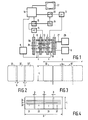
- a magnetic resonance apparatus as shown in Fig. 1 comprises a magnet system 2 for generating a steady uniform magnetic field, a magnet system 4 for generating magnetic gradient fields, power supply sources 6 and 8 for the magnet system 2 and the magnet system 4, respectively.
- a magnet coil 10 for generating an rf magnetic alternating field is connected to an rf source 12.
- a surface coil 13 is provided for the detection of magnetic resonance signals generated by the rf transmitter field in an object to be examined. For reading, the coil 13 is connected to a signal amplifier 14.
- the signal amplifier 14 is connected to a phase-sensitive rectifier 16 which is connected to a central control device 18.
- the central control device 18 also controls a modulator 20 for the rf source 12, the supply source 8 for the gradient coils, and a monitor 22 for display.
- a high frequency oscillator 24 controls the modulator 20 as well as the phase-sensitive rectifier 16 which processes the measured signals.
- a cooling device 26 which comprises cooling ducts 27.
- a cooling device of this kind can be constructed as a water cooling system for resistance coils or as a liquid nitrogen or helium dewar system for superconducting coils.
- the transmitter coil 10 which is arranged within the magnet systems 2 and 4 encloses a measurement space 28 which offers sufficient room for a patient for medical diagnostic measurement.
- the measurement space 28 there can be generated a steady magnetic field, gradient fields for position selection of slices to be imaged, and a spatially uniform rf alternating field.
- the measurement space is shielded against interference fields by a Faraday cage 29.
- a cascade of surface coils 32 so that all cross-sections of the object, in as far as covered by the measurement space 28, can be measured with a suitable signal-to-noise ratio without any displacement of the object of coils being required.
- measurement can be carried out by means of a cascade of surface coils having a dimension of, for example, 20 x 20 cm.
- the coils of the cascade overlap each other in the direction of width. The extent of overlap has been chosen to be so that the mutual inductance between the two coils is minimised by it.
- FIG. 2 A feasible cascade system is diagrammatically shown in Fig. 2 which shows successive coils 32 which overlap each other over a distance b of, for example, 4 cm.
- the geometry and the overlap ensure that no undesired cross-talk occurs between coils of the cascade.
- Transversal slices can be measured with an overlap which is not optimised for uncoupling using electronic uncoupling. If the overlap is optimised in this sense, sagittal and coronal slices can also be measured with a sufficient extent by simultaneously using the coils overlapping each other.
- Fig. 3 shows a cascade of butterfly coils according to the invention in which two successive coils 32 are arranged so that the desired overlap b occurs for the wings as a result of which the coils are mutually uncoupled.
- signals from coils 31, 33, 35 and 37 overlapping each other differently are used for measuring sagittal or coronal cross-sections by supplying these signals, optionally after pre-amplification, to an rf signal processing device, for signal adding and for supplying a single signal for picture formation to a signal receiver.
- an rf signal processing device for signal adding and for supplying a single signal for picture formation to a signal receiver.
- measurement can be carried out with all the coils simultaneously so that the sagittal or coronal image planes can extend over the full width of the coil and the advantage of the favourable signal-to-noise ratio for transversal images is maintained.
- the signal-to-noise ratio the sagittal and coronal images are equal to a single 20 x 60 cm2 coil.
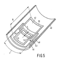
- the coil shown in Fig. 5 comprises a rigid support 40 which can be rigidly mounted to, for example, a patient table or in the magnetic resonance apparatus.
- a first coil 42 is rigidly connected to the support 40 and consists, for example, of copper tape 50 having a thickness of 0.1 mm and a width of 5 mm bonded to the support.
- a second coil 44 is bonded to a rigid slide 46 in a corresponding manner and can be moved in a direction B so that both coils can be made to have an overlap b .
- a measuring ruler 48 for example, an optimum overlap b once fixed can be established.
- a clamping device 52 the slide can be fixed in the desired position with respect to the support 40.
- the slide is preferably constructed so that both coils are situated substantially in one plane but remain electrically insulated.
Landscapes
- Physics & Mathematics (AREA)
- Condensed Matter Physics & Semiconductors (AREA)
- General Physics & Mathematics (AREA)
- Magnetic Resonance Imaging Apparatus (AREA)
Applications Claiming Priority (2)
| Application Number | Priority Date | Filing Date | Title |
|---|---|---|---|
| NL8801018A NL8801018A (nl) | 1988-04-20 | 1988-04-20 | Magnetisch resonantie apparaat met ontkoppelde rf-spoelen. |
| NL8801018 | 1988-04-20 |
Publications (1)
| Publication Number | Publication Date |
|---|---|
| EP0338624A1 true EP0338624A1 (de) | 1989-10-25 |
Family
ID=19852164
Family Applications (1)
| Application Number | Title | Priority Date | Filing Date |
|---|---|---|---|
| EP89200951A Withdrawn EP0338624A1 (de) | 1988-04-20 | 1989-04-14 | Gerät mittels magnetischer Resonanz mit entkoppelten HF-Spulen |
Country Status (3)
| Country | Link |
|---|---|
| EP (1) | EP0338624A1 (de) |
| JP (1) | JPH0213432A (de) |
| NL (1) | NL8801018A (de) |
Cited By (11)
| Publication number | Priority date | Publication date | Assignee | Title |
|---|---|---|---|---|
| DE4232827A1 (de) * | 1992-09-30 | 1994-03-31 | Siemens Ag | Zirkular polarisierte Lokal-Antennenanordnung für ein Kernspintomographiegerät |
| EP0583824A3 (en) * | 1992-08-13 | 1994-06-01 | Philips Patentverwaltung | Coil arrangement for magnetic resonance female breast examination |
| DE4430646A1 (de) * | 1993-08-30 | 1995-03-02 | Hitachi Medical Corp | HF-Sonde |
| DE4432574A1 (de) * | 1993-09-14 | 1995-03-23 | Toshiba Kawasaki Kk | Bildgebende Kernspinresonanz-Vorrichtung |
| DE4434948A1 (de) * | 1994-09-29 | 1996-04-04 | Siemens Ag | Mammographie-Antennenanordnung für Magnetresonanzuntersuchungen einer weiblichen Brust |
| EP0803736A3 (de) * | 1996-04-25 | 1998-04-15 | Philips Patentverwaltung GmbH | MR-Gerät mit einer Zylinderspulenanordnung und einer Oberflächenspulenanordnung |
| NL1026491C2 (nl) * | 2003-06-23 | 2006-08-08 | Gen Electric | Een phased-array spoelsamenstel en werkwijze en systeem voor het toepassen daarvan. |
| US20090118611A1 (en) * | 2007-11-07 | 2009-05-07 | University Of Pittsburgh - Of The Common Wealth System Of Higher Education | Coils for magnetic resonance spectroscopy and imaging of human breast |
| CN112649497A (zh) * | 2020-12-24 | 2021-04-13 | 爱德森(厦门)电子有限公司 | 一种在线监测级联式互感涡流传感器装置及其系统方法 |
| EP3992656A1 (de) * | 2020-10-27 | 2022-05-04 | Koninklijke Philips N.V. | Positionierung von hochfrequenzspulen in magnetresonanzbildgebungsvorrichtungen |
| US12631703B2 (en) | 2020-10-27 | 2026-05-19 | Koninklijke Philips N.V. | Positioning of radiofrequency coils in magnetic resonance imaging devices |
Families Citing this family (2)
| Publication number | Priority date | Publication date | Assignee | Title |
|---|---|---|---|---|
| JP2680235B2 (ja) * | 1991-11-26 | 1997-11-19 | 株式会社日立製作所 | 核磁気共鳴装置用プローブ |
| JP2814222B2 (ja) * | 1996-06-21 | 1998-10-22 | 株式会社ワカ製作所 | コネクター及びその製造方法 |
Citations (7)
| Publication number | Priority date | Publication date | Assignee | Title |
|---|---|---|---|---|
| DE3323657A1 (de) * | 1982-07-07 | 1984-01-12 | Instrumentarium Oy, 00101 Helsinki | Spulenanordnung |
| EP0142077A1 (de) * | 1983-11-08 | 1985-05-22 | Siemens Aktiengesellschaft | Hochfrequenz-Einrichtung einer Kernspinresonanz-Apparatur mit einer Oberflächenspule |
| EP0171741A2 (de) * | 1984-08-16 | 1986-02-19 | General Electric Company | Körpersonden mit mindestens einer Oberflächenspule für magnetische Kernresonanzspektroskopie |
| EP0175129A2 (de) * | 1984-08-16 | 1986-03-26 | General Electric Company | Antennenanordnung mit einer Mehrzahl von nichtorthogonalen Oberflächenspulen für Bilderzeugung mittels magnetischer Kernresonanz |
| EP0218290A1 (de) * | 1985-09-25 | 1987-04-15 | Koninklijke Philips Electronics N.V. | Magnetischer Resonanzapparat mit einer entkoppelten Oberflächenempfangsspule |
| EP0234786A2 (de) * | 1986-02-10 | 1987-09-02 | The Regents Of The University Of California | Quadratur-Spulen, angepasst zur Bilderzeugung mittels magnetischer Resonanz mit minimalisierter Kopplung zwischen den Spulen |
| EP0273484A2 (de) * | 1986-11-27 | 1988-07-06 | Koninklijke Philips Electronics N.V. | Vorrichtung zur Bilderzeugung mittels magnetischer Resonanz mit gestapeltem Oberflächenspulensystem |
-
1988
- 1988-04-20 NL NL8801018A patent/NL8801018A/nl not_active Application Discontinuation
-
1989
- 1989-04-14 EP EP89200951A patent/EP0338624A1/de not_active Withdrawn
- 1989-04-17 JP JP1095434A patent/JPH0213432A/ja active Pending
Patent Citations (7)
| Publication number | Priority date | Publication date | Assignee | Title |
|---|---|---|---|---|
| DE3323657A1 (de) * | 1982-07-07 | 1984-01-12 | Instrumentarium Oy, 00101 Helsinki | Spulenanordnung |
| EP0142077A1 (de) * | 1983-11-08 | 1985-05-22 | Siemens Aktiengesellschaft | Hochfrequenz-Einrichtung einer Kernspinresonanz-Apparatur mit einer Oberflächenspule |
| EP0171741A2 (de) * | 1984-08-16 | 1986-02-19 | General Electric Company | Körpersonden mit mindestens einer Oberflächenspule für magnetische Kernresonanzspektroskopie |
| EP0175129A2 (de) * | 1984-08-16 | 1986-03-26 | General Electric Company | Antennenanordnung mit einer Mehrzahl von nichtorthogonalen Oberflächenspulen für Bilderzeugung mittels magnetischer Kernresonanz |
| EP0218290A1 (de) * | 1985-09-25 | 1987-04-15 | Koninklijke Philips Electronics N.V. | Magnetischer Resonanzapparat mit einer entkoppelten Oberflächenempfangsspule |
| EP0234786A2 (de) * | 1986-02-10 | 1987-09-02 | The Regents Of The University Of California | Quadratur-Spulen, angepasst zur Bilderzeugung mittels magnetischer Resonanz mit minimalisierter Kopplung zwischen den Spulen |
| EP0273484A2 (de) * | 1986-11-27 | 1988-07-06 | Koninklijke Philips Electronics N.V. | Vorrichtung zur Bilderzeugung mittels magnetischer Resonanz mit gestapeltem Oberflächenspulensystem |
Cited By (22)
| Publication number | Priority date | Publication date | Assignee | Title |
|---|---|---|---|---|
| EP0583824A3 (en) * | 1992-08-13 | 1994-06-01 | Philips Patentverwaltung | Coil arrangement for magnetic resonance female breast examination |
| US5416413A (en) * | 1992-08-13 | 1995-05-16 | U. S. Philips Corporation | Magnetic resonance examination apparatus comprising a coil system for MR mammography |
| DE4232827A1 (de) * | 1992-09-30 | 1994-03-31 | Siemens Ag | Zirkular polarisierte Lokal-Antennenanordnung für ein Kernspintomographiegerät |
| US5471142A (en) * | 1992-09-30 | 1995-11-28 | Siemens Aktiengesellschaft | Circularly polarized local antenna arrangement for a nuclear magnetic resonance tomography apparatus and method for operating same |
| DE4232827B4 (de) * | 1992-09-30 | 2004-08-05 | Siemens Ag | Zirkular polarisierte Lokal-Antennenanordnung für ein Kernspintomographiegerät |
| DE4430646A1 (de) * | 1993-08-30 | 1995-03-02 | Hitachi Medical Corp | HF-Sonde |
| US5552707A (en) * | 1993-08-30 | 1996-09-03 | Hitachi Medical Corporation | RF probe which can vary distance between receiving coils which face each other |
| DE4430646C2 (de) * | 1993-08-30 | 1999-08-05 | Hitachi Medical Corp | HF-Sonde und Kernspintomograph mit einer solchen HF-Sonde |
| DE4432574A1 (de) * | 1993-09-14 | 1995-03-23 | Toshiba Kawasaki Kk | Bildgebende Kernspinresonanz-Vorrichtung |
| DE4432574C2 (de) * | 1993-09-14 | 1999-11-18 | Toshiba Kawasaki Kk | Bildgebende Kernspinresonanz-Vorrichtung |
| DE4434948C2 (de) * | 1994-09-29 | 1998-05-20 | Siemens Ag | Mammographie-Antennenanordnung für Magnetresonanzuntersuchungen einer weiblichen Brust |
| US5602557A (en) * | 1994-09-29 | 1997-02-11 | Siemens Aktiengesellschaft | Mammography antenna arrangement for NMR examinations of a female breast |
| DE4434948A1 (de) * | 1994-09-29 | 1996-04-04 | Siemens Ag | Mammographie-Antennenanordnung für Magnetresonanzuntersuchungen einer weiblichen Brust |
| EP0803736A3 (de) * | 1996-04-25 | 1998-04-15 | Philips Patentverwaltung GmbH | MR-Gerät mit einer Zylinderspulenanordnung und einer Oberflächenspulenanordnung |
| NL1026491C2 (nl) * | 2003-06-23 | 2006-08-08 | Gen Electric | Een phased-array spoelsamenstel en werkwijze en systeem voor het toepassen daarvan. |
| US20090118611A1 (en) * | 2007-11-07 | 2009-05-07 | University Of Pittsburgh - Of The Common Wealth System Of Higher Education | Coils for magnetic resonance spectroscopy and imaging of human breast |
| US8731635B2 (en) * | 2007-11-07 | 2014-05-20 | University of Pittsburgh—of the Commonwealth System of Higher Education | Coils for magnetic resonance spectroscopy and imaging of human breast |
| EP3992656A1 (de) * | 2020-10-27 | 2022-05-04 | Koninklijke Philips N.V. | Positionierung von hochfrequenzspulen in magnetresonanzbildgebungsvorrichtungen |
| WO2022090137A1 (en) * | 2020-10-27 | 2022-05-05 | Koninklijke Philips N.V. | Positioning of radiofrequency coils in magnetic resonance imaging devices |
| US12631703B2 (en) | 2020-10-27 | 2026-05-19 | Koninklijke Philips N.V. | Positioning of radiofrequency coils in magnetic resonance imaging devices |
| CN112649497A (zh) * | 2020-12-24 | 2021-04-13 | 爱德森(厦门)电子有限公司 | 一种在线监测级联式互感涡流传感器装置及其系统方法 |
| CN112649497B (zh) * | 2020-12-24 | 2023-04-25 | 爱德森(厦门)电子有限公司 | 一种在线监测级联式互感涡流传感器装置及其系统方法 |
Also Published As
| Publication number | Publication date |
|---|---|
| JPH0213432A (ja) | 1990-01-17 |
| NL8801018A (nl) | 1989-11-16 |
Similar Documents
| Publication | Publication Date | Title |
|---|---|---|
| US4943775A (en) | Magnetic resonance apparatus with uncoupled rf coils | |
| EP0274773B1 (de) | Vorrichtung zur Bilderzeugung mittels magnetischer Resonanz mit einem Quadratur-Spulensystem | |
| US5610521A (en) | Gradient and RF coil system without RF shield | |
| EP0218290B1 (de) | Magnetischer Resonanzapparat mit einer entkoppelten Oberflächenempfangsspule | |
| EP0366188B1 (de) | Kernspinresonanzgerät mit verbesserter Hf-Spule | |
| EP0273484B1 (de) | Vorrichtung zur Bilderzeugung mittels magnetischer Resonanz mit gestapeltem Oberflächenspulensystem | |
| US5898306A (en) | Single circuit ladder resonator quadrature surface RF coil | |
| EP0805987B1 (de) | System zur bilderzeugung durch magnetische resonanz und katheter für eingriffsverfahren | |
| US5207224A (en) | Magnetic resonance apparatus | |
| EP0359374A1 (de) | Kernspinresonanzgerät | |
| US6029081A (en) | Movable magnets for magnetic resonance surgery | |
| EP0768539A2 (de) | Verfahren und Gerät für die magnetische Resonanz | |
| JPS5999239A (ja) | 核磁気共鳴トモグラフイ−装置 | |
| JP3411631B2 (ja) | Rfプローブ及び磁気共鳴イメージング装置 | |
| EP0529730B1 (de) | Kernspinresonanzgerät mit entkoppelten Empfangsspulen | |
| EP1456680B1 (de) | Kernspintomograph mit in die patientenlage integriertem niedrigfrequenz-kabel | |
| EP0637755A1 (de) | Apparat zur Bilderzeugung mittels magnetischer Resonanz | |
| US5293126A (en) | Local transverse gradient coil | |
| US5942898A (en) | Thrust balanced bi-planar gradient set for MRI scanners | |
| JPH0213432A (ja) | 非結合のrfコイルによる磁気共鳴装置 | |
| US4864240A (en) | Magnet systems | |
| WO1999054747A1 (en) | Magnetic gradient field projection | |
| US5329232A (en) | Magnetic resonance methods and apparatus | |
| CN103105598B (zh) | 局部线圈 | |
| JPH02111342A (ja) | 直角位相コイルを有する磁気共鳴イメージング装置 |
Legal Events
| Date | Code | Title | Description |
|---|---|---|---|
| PUAI | Public reference made under article 153(3) epc to a published international application that has entered the european phase |
Free format text: ORIGINAL CODE: 0009012 |
|
| AK | Designated contracting states |
Kind code of ref document: A1 Designated state(s): DE FR GB IT NL |
|
| 17P | Request for examination filed |
Effective date: 19900423 |
|
| 17Q | First examination report despatched |
Effective date: 19910604 |
|
| STAA | Information on the status of an ep patent application or granted ep patent |
Free format text: STATUS: THE APPLICATION IS DEEMED TO BE WITHDRAWN |
|
| 18D | Application deemed to be withdrawn |
Effective date: 19911015 |