EP0338814B1 - Système de suspension automobile à caractéristiques de suspension variables et amortisseur variable pour dito - Google Patents
Système de suspension automobile à caractéristiques de suspension variables et amortisseur variable pour dito Download PDFInfo
- Publication number
- EP0338814B1 EP0338814B1 EP19890303903 EP89303903A EP0338814B1 EP 0338814 B1 EP0338814 B1 EP 0338814B1 EP 19890303903 EP19890303903 EP 19890303903 EP 89303903 A EP89303903 A EP 89303903A EP 0338814 B1 EP0338814 B1 EP 0338814B1
- Authority
- EP
- European Patent Office
- Prior art keywords
- mode
- pressure
- piston
- damping
- deadband
- Prior art date
- Legal status (The legal status is an assumption and is not a legal conclusion. Google has not performed a legal analysis and makes no representation as to the accuracy of the status listed.)
- Expired - Lifetime
Links
- 238000013016 damping Methods 0.000 title claims description 95
- 239000000725 suspension Substances 0.000 title claims description 81
- 230000035939 shock Effects 0.000 title claims description 41
- 239000006096 absorbing agent Substances 0.000 title claims description 38
- 239000012530 fluid Substances 0.000 claims description 63
- 230000006835 compression Effects 0.000 claims description 49
- 238000007906 compression Methods 0.000 claims description 49
- 230000004044 response Effects 0.000 claims description 32
- 238000004891 communication Methods 0.000 claims description 25
- 230000001276 controlling effect Effects 0.000 claims description 23
- 230000007423 decrease Effects 0.000 claims description 5
- 230000001105 regulatory effect Effects 0.000 claims description 2
- 238000000034 method Methods 0.000 description 28
- 230000008569 process Effects 0.000 description 28
- 238000010276 construction Methods 0.000 description 8
- 239000003990 capacitor Substances 0.000 description 7
- 230000007246 mechanism Effects 0.000 description 7
- 238000012544 monitoring process Methods 0.000 description 6
- 230000004323 axial length Effects 0.000 description 5
- 206010034719 Personality change Diseases 0.000 description 4
- 230000009471 action Effects 0.000 description 4
- 230000003247 decreasing effect Effects 0.000 description 3
- 238000010586 diagram Methods 0.000 description 3
- 239000000428 dust Substances 0.000 description 3
- 230000004048 modification Effects 0.000 description 3
- 238000012986 modification Methods 0.000 description 3
- 230000007935 neutral effect Effects 0.000 description 3
- 230000000903 blocking effect Effects 0.000 description 2
- 230000015556 catabolic process Effects 0.000 description 2
- 238000006731 degradation reaction Methods 0.000 description 2
- 238000006073 displacement reaction Methods 0.000 description 2
- 238000005516 engineering process Methods 0.000 description 2
- 230000006870 function Effects 0.000 description 2
- 230000000087 stabilizing effect Effects 0.000 description 2
- 239000004809 Teflon Substances 0.000 description 1
- 229920006362 Teflon® Polymers 0.000 description 1
- 238000010521 absorption reaction Methods 0.000 description 1
- 238000013459 approach Methods 0.000 description 1
- 230000009286 beneficial effect Effects 0.000 description 1
- 230000001419 dependent effect Effects 0.000 description 1
- 238000007599 discharging Methods 0.000 description 1
- 230000000694 effects Effects 0.000 description 1
- 239000013013 elastic material Substances 0.000 description 1
- 238000002474 experimental method Methods 0.000 description 1
- 239000002783 friction material Substances 0.000 description 1
- 230000013011 mating Effects 0.000 description 1
- 238000004904 shortening Methods 0.000 description 1
- 230000006641 stabilisation Effects 0.000 description 1
- 238000011105 stabilization Methods 0.000 description 1
- 230000001629 suppression Effects 0.000 description 1
- XLYOFNOQVPJJNP-UHFFFAOYSA-N water Substances O XLYOFNOQVPJJNP-UHFFFAOYSA-N 0.000 description 1
Images



Classifications
-
- B—PERFORMING OPERATIONS; TRANSPORTING
- B60—VEHICLES IN GENERAL
- B60G—VEHICLE SUSPENSION ARRANGEMENTS
- B60G17/00—Resilient suspensions having means for adjusting the spring or vibration-damper characteristics, for regulating the distance between a supporting surface and a sprung part of vehicle or for locking suspension during use to meet varying vehicular or surface conditions, e.g. due to speed or load
- B60G17/015—Resilient suspensions having means for adjusting the spring or vibration-damper characteristics, for regulating the distance between a supporting surface and a sprung part of vehicle or for locking suspension during use to meet varying vehicular or surface conditions, e.g. due to speed or load the regulating means comprising electric or electronic elements
- B60G17/019—Resilient suspensions having means for adjusting the spring or vibration-damper characteristics, for regulating the distance between a supporting surface and a sprung part of vehicle or for locking suspension during use to meet varying vehicular or surface conditions, e.g. due to speed or load the regulating means comprising electric or electronic elements characterised by the type of sensor or the arrangement thereof
- B60G17/01941—Resilient suspensions having means for adjusting the spring or vibration-damper characteristics, for regulating the distance between a supporting surface and a sprung part of vehicle or for locking suspension during use to meet varying vehicular or surface conditions, e.g. due to speed or load the regulating means comprising electric or electronic elements characterised by the type of sensor or the arrangement thereof characterised by the use of piezoelectric elements, e.g. sensors or actuators
-
- B—PERFORMING OPERATIONS; TRANSPORTING
- B60—VEHICLES IN GENERAL
- B60G—VEHICLE SUSPENSION ARRANGEMENTS
- B60G2202/00—Indexing codes relating to the type of spring, damper or actuator
- B60G2202/20—Type of damper
- B60G2202/24—Fluid damper
-
- B—PERFORMING OPERATIONS; TRANSPORTING
- B60—VEHICLES IN GENERAL
- B60G—VEHICLE SUSPENSION ARRANGEMENTS
- B60G2400/00—Indexing codes relating to detected, measured or calculated conditions or factors
- B60G2400/20—Speed
- B60G2400/204—Vehicle speed
-
- B—PERFORMING OPERATIONS; TRANSPORTING
- B60—VEHICLES IN GENERAL
- B60G—VEHICLE SUSPENSION ARRANGEMENTS
- B60G2400/00—Indexing codes relating to detected, measured or calculated conditions or factors
- B60G2400/25—Stroke; Height; Displacement
- B60G2400/252—Stroke; Height; Displacement vertical
-
- B—PERFORMING OPERATIONS; TRANSPORTING
- B60—VEHICLES IN GENERAL
- B60G—VEHICLE SUSPENSION ARRANGEMENTS
- B60G2400/00—Indexing codes relating to detected, measured or calculated conditions or factors
- B60G2400/50—Pressure
- B60G2400/51—Pressure in suspension unit
- B60G2400/518—Pressure in suspension unit in damper
- B60G2400/5182—Fluid damper
-
- B—PERFORMING OPERATIONS; TRANSPORTING
- B60—VEHICLES IN GENERAL
- B60G—VEHICLE SUSPENSION ARRANGEMENTS
- B60G2401/00—Indexing codes relating to the type of sensors based on the principle of their operation
- B60G2401/10—Piezoelectric elements
-
- B—PERFORMING OPERATIONS; TRANSPORTING
- B60—VEHICLES IN GENERAL
- B60G—VEHICLE SUSPENSION ARRANGEMENTS
- B60G2500/00—Indexing codes relating to the regulated action or device
- B60G2500/10—Damping action or damper
-
- B—PERFORMING OPERATIONS; TRANSPORTING
- B60—VEHICLES IN GENERAL
- B60G—VEHICLE SUSPENSION ARRANGEMENTS
- B60G2500/00—Indexing codes relating to the regulated action or device
- B60G2500/10—Damping action or damper
- B60G2500/102—Damping action or damper stepwise
-
- B—PERFORMING OPERATIONS; TRANSPORTING
- B60—VEHICLES IN GENERAL
- B60G—VEHICLE SUSPENSION ARRANGEMENTS
- B60G2600/00—Indexing codes relating to particular elements, systems or processes used on suspension systems or suspension control systems
- B60G2600/02—Retarders, delaying means, dead zones, threshold values, cut-off frequency, timer interruption
-
- B—PERFORMING OPERATIONS; TRANSPORTING
- B60—VEHICLES IN GENERAL
- B60G—VEHICLE SUSPENSION ARRANGEMENTS
- B60G2600/00—Indexing codes relating to particular elements, systems or processes used on suspension systems or suspension control systems
- B60G2600/66—Humidifying or drying means
Definitions
- the present invention relates generally to a suspension system for an automotive vehicle, which is variable of suspension characteristics with high response characteristics. More specifically, the invention relates to an automotive suspension system which is variable of damping characteristics per every vibration cycles. The invention further relates to a variable damping shock absorber which is applicable for the automotive suspension system.
- a piezoelectric element is disposed in each shock absorber in each suspension system for detecting variation of fluid pressure in the shock absorber.
- a control unit is provided for receiving an input indicative of the fluid pressure provided from the piezoelectric element.
- the control unit outputs a controlled voltage to the piezoelectric element for switching operation mode of the shock absorber at least between SOFT mode in which smaller damping force is to be generated in response to vibration input and HARD mode in which greater damping force is to be generated in response to vibration input.
- control unit is responsive to low frequency input vibration which induces attitude change of the vehicle body to switch the operational mode of the shock absorber into HARD mode for a given period of time. While the shock absorber is maintained at the HARD mode, the piezoelectric element maintains operation as an actuator for maintaining HARD mode operation of the shock absorber. Therefore, while it is active as the actuator, the piezoelectric element can not monitor fluid pressure.
- damping force generated in response to piston compression mode action can amplify the input vibration. This tendency may be significant for the second and subsequent vibration cycles. This clearly degrades vibration stabilizing performance of the vehicle to provide rough ride feeling.
- WO 87/07565 on which the preamble of claim 1 is based, discloses a suspension control system in which the suspension characteristics are switched from SOFT to HARD if the relative speed of the piston in the cylinder (determined by measuring the pressure difference between the working chambers on either side of the piston) exceeds a predetermined threshold.
- US-A-4 696 489 discloses a suspension control system in which the suspension characteristics are set to HARD if the relative speed of the piston in the cylinder exceeds a predetermined threshold, or if the position of the piston in the cylinder moves away from an average position by more than a predetermined amount, except that the suspension characteristics are kept soft if the direction of movement of the wheel relative to the vehicle body is the same as the absolute direction of movement of the vehicle body.
- Another object of the present invention is to provide a variable damping force shock absorber for use in the suspension system of the invention.
- the invention provides an automotive suspension system comprising: a shock absorber comprising a cylinder tube connected with one of a vehicle body and a suspension member rotatably supporting a road wheel, and a piston which is connected with the other of said vehicle body and road wheel, and slidably received in said cylinder tube so as to divide the internal cavity of said cylinder tube into first and second working fluid chambers; fluid communication means for establishing fluid communication between said first and second chambers with a limited fluid flow rate for generating a damping force against relative motion between said piston and said cylinder tube; valve means associated with said fluid communication means for regulating the flow restriction of said fluid communication means to vary a damping characteristic of said shock absorber; sensing means for responding to a fluid pressure of said shock absorber and producing a first pressure signal; actuator means for manipulating said valve means to vary the flow restriction characteristic in response to a control signal; and controlling means for controlling the damping characteristic by producing said control signal in accordance with the pressure signal; characterised in that said controlling means determines a variation rate of the sensed pressure
- the controlling means may be arranged to receive the piston stroke indicative signal, for deriving piston motion representative data on the basis of the piston stroke indicative signal, compare the piston motion representative data with a predetermined deadband criterion that is set with respect to a neutral value and defining a predetermined deadband, detect the piston motion representative data out of the deadband and reaching a peak value for producing the control signal for harder damping characteristics, and detect the piston motion representative data entering into the deadband.
- the controlling means may be arranged to compare the piston motion representative data with predetermined deadband criteria which are set with respect to a neutral value, define a predetermined deadband for producing the control signal for harder damping characteristics, and detect the piston motion representative data varying across one of the deadband criteria to be out of the deadband.
- the controlling means may be arranged to detect the pressure variation representative data varying across the neutral value for prroducing the control signal for softer damping characteristics. Instead, the controlling means may be arranged to detect the pressure variation representative data entering into the deadband for producing the control signal for softer damping characteristics.
- controlling means may be arranged to detect the pressure variation representative data varying across one of the deadband criteria to be out of the deadband for producing the control signal for softer damping characteristics.
- the sensor means may comprise a first piezoelectric element and the actuating means a second piezoelectric element.
- the controlling means may increase the control signal value at a predetermined rate for increasing flow restriction at a predetermined rate.
- the controlling means may decrease the control signal value at a predetermined rate for decreasing flow restriction at a predetermined rate.
- the automotive suspension may comprise a vehicle speed sensor for monitoring a vehicle speed to produce a vehicle speed indicative signal, and arithmetic means arranged to vary the deadband criteria according to variation of the value of the vehicle speed indicative signal.
- the arithmetic means may continuously vary the deadband criteria for varying the width of the deadband according to variation of the value of the vehicle speed indicative signal.
- the arithmetic means may vary the deadband criteria for varying the width of the deadband in stepwise fashion according to variation of the value of the vehicle speed indicative signal.
- the arithmetic means varies the width of the deadband between a first wider width and a second narrower width which is selected when the value of the vehicle speed indicative signal is greater than a predetermined first vehicle speed criterion.
- the arithmetic means may set a second vehicle speed criterion at a value smaller than the first vehicle speed criterion for switching the width of the deadband from the narrower width to the wider width when the vehicle speed indicative signal value decreases thereacross.
- the shown shock absorber 1 comprises a double action type shock absorber variable of damping characteristics.
- the shock absorber 1 has inner and outer cylinder tubes 3 and 2 .
- the inner and outer cylinders 3 and 2 are arranged in coaxial arrangement for defining an annular chamber 7 which serves as a reservoir chamber.
- a piston assembly 4 is disposed within the internal space of the inner cylinder tube 3 for dividing the internal space into upper and lower working chambers 14 and 15 .
- the piston assembly 4 is supported on the lower end of a piston rod 6 .
- the piston rod 6 is a guided by a rod guide 8 is engaged in the top end opening of the inner cylinder tube 3 .
- the rod guide 8 cooperates with a piston seal 9 and a stopper plate 10 to form an upper plug assembly for sealingly closing the top ends of the inner and outer cylinder tubes 3 and 2 .
- the top end of the piston rod 6 is connected to a vehicle body (not shown) in per se known manner.
- a connecting eye 32 with an eye bushing 31 is provided on the lower end of the outer cylinder tube 2 .
- the outer cylinder tube 2 is connected to a suspension member (not shown) rotatably supporting a road wheel.
- the shock absorber 1 is disposed between the vehicle body and the suspension member to receive vibration energy causing relative displacement between the vehicle body and the suspension member.
- the shock absorber 1 is compressed in response to bounding stroke motion, in which the vehicle body and the suspension member are shifted to approach to each other, and expanded in response to a rebounding stroke motion, in which the vehicle body and suspension member are shifted away to each other.
- the piston assembly 4 strokes in compression stroke direction with compressing the lower working chamber 15 .
- This causes increasing of working fluid pressure in the lower working chamber and decreasing of the working fluid pressure in the higher working chamber.
- the piston assembly 4 strokes in expansion stroke direction with compressing the higher working chamber 14 . Therefore, the fluid pressure in the upper working chamber 14 is increased and the fluid pressure in the lower working chamber 15 is decreased.
- the fluid reservoir chamber 7 is normally maintained at a pressure substantially corresponding to fluid pressure in the lower working chamber 15 . stroke motion,
- the lower end opening of the inner cylinder 3 is closed by a bottom valve assembly 12 which defines a communication path 11 .
- the bottom valve assembly 12 thus establishes fluid communication between the fluid reservoir chamber 7 and the lower working chamber 15 .
- the piston assembly 4 accompanies an expansion valve 16 which is effective in a piston expansion stroke to produce a damping force.
- the expansion valve 16 is associated with a bias spring 17 which is active on the expansion valve 16 to constantly bias the latter in upward direction.
- the bias spring is mounted on the lower end of the piston rod 6 by means of an adjuster nut 18 and a lock nut 19 .
- An adjuster nut 20 also engages with the lower end of the piston rod 6 .
- the bottom valve assembly 5 has a check valve 21 associated with a port 22 for openably closing the port.
- the check valve 21 is designed to open during piston expansion stroke to permit fluid flow from the reservoir chamber 7 to the lower working chamber 15 .
- the bottom valve 5 is also provided with a compression valve 23 which is associated with the lower end of an orifice 24 to open in response to compression stroke in order to establish fluid communication from the lower working chamber 15 to the reservoir chamber 7 .
- the check valve 21 and the compression valve 23 are mounted and secured on a bottom valve body 12 by means of a clamping pin 26 .
- a stopper plate 25 is also mounted on the bottom valve body 12 in order to restrict magnitude of opening of the check valve 21 .
- the check valve 21 is responsive to the pressure difference between the lower working chamber 15 and the fluid reservoir chamber 7 to be shifted to the open position for introducing the working fluid in the fluid reservoir chamber into the lower working chamber.
- pressure difference between the lower working chamber 15 and the fluid reservoir chamber 7 is created to shift the compression valve 23 .
- By opening of the compression valve 23 a limited flow rate of the working fluid is permitted to flow from the lower working chamber 15 to the fluid reservoir chamber 7 with generating a damping force.
- a rebounding stopper 28 which is made of an elastic material, such as a rubber, is mounted on the piston rod 6 by means of a retainer 27 .
- the rebounding stopper 28 protects the piston assembly 4 from direct collision onto the lower end of the rod guide 8 .
- the stopper plate 10 is clamped onto the upper end of the outer cylinder tube 2 .
- the stopper 10 defines a center opening 10a , through which the piston rod 6 extends.
- a rubber bushing (not shown) engages with the periphery of the center opening 10a of the stopper plate 10 for slidingly and sealingly guide the piston rod 6 .
- a main lip 29 and a dust lip 30 are also provided in the upper plug assembly. The main lip 29 sealingly contact with the outer periphery of the piston rod for establishing a fluid tight seal.
- the dust lip 30 is provided in the vicinity of the stopper plate and contacts with the outer periphery of the piston rod 4 to establish fluid tight seal so as to prevent the muddy water, dust and so forth.
- the piston assembly 4 is designed to vary damping characteristics to generate damping force in response to vibration input according to variable characteristics in different damping mode.
- a control unit 100 is connected to the piston assembly via a harness 35 which extends through the piston rod.
- Fig. 2 shows the detailed construction of the piston assembly 4 employed in the preferred embodiment of the shock absorber 1 of Fig. 1 .
- the piston rod 6 defined an axially extending through opening 41 through which the wiring harness 35 extends.
- the lower end of the through opening 41 is communicated with a threaded groove 41a forming a piston receptacle.
- the piston assembly 4 includes a piston body 42 which has an upward extension which threadingly engages with the threaded groove 41a of the piston rod 6 so that the piston body 42 is firmly mounted on the lower end of the piston rod 6 .
- the piston body 42 has an outer periphery mating with the inner periphery of the inner cylinder 3 .
- a low friction seal member 44 which is made of a low friction material, such as a teflon, engages on the outer periphery of the piston body 42 for establishing the fluid tight seal between the inner periphery of the inner cylinder 3 .
- the piston body 42 has a threaded lower end, to which the upper end of a sleeve 43 engages.
- the aforementioned adjusting nut 18 , the lock nut 19 and the adjusting nut 20 are engaged onto the outer periphery of the lower end portion of the sleeve 43 .
- the piston body 42 defines an internal space 45 which is in communication with the upper and lower working chambers via communication path 46 and 47 defined therethrough.
- the sleeve 43 defines a through opening 48 for communication between the internal space 45 and the lower working chamber 15 .
- the expansion valve 16 is associated with the end of the through opening 48 opening to the lower working chamber 15 so as to restrict fluid flow path area for generating damping force.
- the expansion valve 16 is responsive to a fluid pressure overcoming the spring force of the bias spring 17 to widen the path area for pressure relieving function.
- the assembly of the piston body 42 and the sleeve 43 defines first and second chambers 49 and 50 of essentially circular cross section. These first and second chambers 49 and 50 have smaller diameter than the space 45 and communicated with the later.
- a first piezoelectric element 60 is disposed within the first chamber 49 .
- the first piezoelectric element 60 has an upper section associated with an adjusting mechanism 51 .
- the adjusting mechanism 51 comprises an adjuster screw 53 engaging with a female thread 52 formed on the inner periphery of the top end of the piston body 42 .
- the adjuster nut 53 has a lower end coupled with an upper end plate 56 fixed onto the upper end of the piezoelectric element 60 via a contact plate 54 and a cap 55 .
- the adjuster screw 53 is manually rotatable for axial shifting to cause axial displacement of the piezoelectric element 60 .
- the piezoelectric element 60 is associated with a slider member 71 via a lower end plate 59 .
- a second piezoelectric element 90 is disposed within the second chamber 50 .
- the second piezoelectric element 90 is supported within the second chamber by means of a cap 94 and the adjuster nut 20 , so that the axial position thereof can be adjusted by means of the adjusting nut.
- the upper end of the second piezoelectric element 90 is associated with a valve core 72 via an upper end plate 88 .
- the slider 71 and the valve bore 72 are associated with a valve body 73 to form a damping mode control mechanism 70 .
- the valve body 73 is disposed within the space 45 to define therein upper and lower annular chambers 79 and 80 .
- the valve body 73 further defines an annular chamber 81 defined between the outer periphery of the valve body 73 and the inner periphery of the piston body 42 .
- the upper annular chamber 79 is in communication with the upper working chamber 14 via a communication path 48 .
- the lower annular chamber 80 is in communication with the flow working chamber 15 via the through opening 48 .
- the annular chamber 81 is in communication with the lower working chamber 15 with the fluid path 47 .
- the valve body 73 defines a center opening 82 through which an upper cylindrical section 83 of the valve core 72 extends, and communication orifices 76 and 77 .
- the communication orifice 76 opens to an annular groove 84 formed on the upper surface of the valve body and surrounded by an annular land 85 .
- the annular groove 84 is exposed to the upper annular chamber 79 .
- the communication orifice 76 also opens to the annular chamber 81 .
- the communication orifice 77 opens to an annular groove 87 formed on the lower surface of the valve body 72 and surrounded by an annular land 86 .
- the annular groove 86 is exposed to the lower annular chamber 80 .
- the communication orifice 77 also opens to the upper annular chamber 79 .
- Upper and lower valve members 74 and 75 are provided for openably closing the annular grooves 84 and 87 and whereby blocking fluid communication between the annular grooves and the associated annular chambers 79 and 80 .
- the valve members 74 and 75 comprises leaf springs resiliently deformable in response to the pressure exerted thereto. Normally, the valve members 74 and 75 are supported at the center boss sections projecting at the center portion of valve body. At this position, the lever length of the valve members 74 and 75 is relatively large to have an initial stiffness to cause resilient deformation in response to the fluid pressure exerted thereto.
- the damping mode where the valve member 74 and 75 operates in smaller stiffness, in which the annular projections 71b and 72 of the slider and valve core are not active will be referred to as SOFT mode.
- the damping mode where the annular projections are active to increase stiffness will be hereafter referred to as HARD mode.
- valve members 74 and 75 can comprise a plurality of thin disc shaped relief springs for resilient deformation in response to the fluid pressure exerted thereonto.
- the first and second piezoelectric elements 60 and 90 are connected to the control unit 100 via cables 61 , 62 , 91 and 92 which forms the wiring harness.
- the cables 61 and 91 connect respectively associated piezoelectric elements 60 and 90 to the ground.
- the cables 62 and 92 connect the piezoelectric elements 60 and 90 .
- Each of the piezoelectric elements 60 and 90 comprises a plurality of thin disc shaped piezoelectric plates piled up in series. Each of the piezoelectric plates respectively having a pair of electrodes.
- the magnitude of electrodistortion is variable depending upon the magnitude of voltage applied to the piezoelectric plates. Such electrodistortion may cause mechanical distortion of the piezoelectric element to cause variation of the axial length.
- each of the piezoelectric plate as the components of the piezoelectric elements is caused mechanical distortion for producing an electric power.
- the magnitude of the electric power to be generated by the piezoelectric elements 60 and 90 is variable depending upon the magnitude of the mechanical distortion and whereby corresponding to the magnitude of the pressure exerted on the piezoelectric elements.
- the first piezoelectric element 60 is subject a fluid pressure of the annular chamber 81 exerted on the valve member 74 which corresponds to the fluid pressure in the lower working chamber 15 via the slider.
- the first piezoelectric element 60 is thus produces a compression mode pressure indicative signal Sp .
- the second piezoelectric element 90 is subject fluid pressure in the upper annular chamber 79 exerted on the valve member via the valve member 75 and the valve core 72 , which fluid pressure corresponds to that in the upper fluid chamber 14 .
- the second piezoelectric element 90 thus produces a expansion mode pressure indicative signal Ss .
- the magnitude of the compression mode pressure indicative signal Sp and the expansion mode pressure indicative signal Ss are variable depending upon the magnitude of pressure in the upper and lower working chambers 14 and 15 .
- the fluid pressure in the lower working chamber 15 is also exerted on the second piezoelectric element 90 via the adjuster nut 20 and a cap 94 .
- the second piezoelectric element 90 outputs the expansion mode pressure indicative signal Ss . Therefore, in the piston expansion stroke, only expansion mode pressure indicative signal Ss is output from the piezoelectric element 90 .
- both of the compression mode and expansion mode pressure indicative signals Sp and Ss are output from the first and second piezoelectric elements 60 and 90 .
- the piezoelectric elements 60 and 90 feeds the compression mode pressure indicative signal Sp and the expansion mode pressure indicative signal Ss to the control unit 100 .
- the control unit 100 processes these compression mode and expansion mode pressure indicative signals Sp and Ss to produce an expansion mode control signal S A and a compression mode control signal S B .
- the expansion mode control signal S A is fed to the first piezoelectric element 60 for controlling axial length thereof to adjust the position of the valve core 72 and whereby adjust the stiffness of the valve members 74 and 75 . By adjusting the stiffness of the valve member 75 , the damping characteristics in response to the piston expansion stroke can be switched between HARD mode and SOFT mode.
- the compression mode control signal S B is applied to the second piezoelectric element 90 for controlling the axial length thereof to adjust the position of the slider 71 relative to the valve members 74 and 75 and whereby adjusts the stiffness of the associated valve member in order to switch the damping mode between HARD mode and SOFT mode. By this, the damping characteristics in the piston compression stroke can be adjusted.
- the control unit 100 comprises a microprocessor based circuit including an input/output (I/O) port 101 , an input circuit 110 , an arithmetic circuit 120 , a driver circuit 130 and a driver power source circuit 140 .
- the I/O unit 101 is connected to respective damping control mechanisms 70 of the shock absorbers 1 disposed in front-left, front-right, rear-left and rear-right suspension systems via the cables 62 and 92 of the wiring harnesses 35 .
- the compression mode pressure indicative signals Sp and the expansion mode pressure indicative signals Ss generated by the piezoelectric elements 60 and 90 of respective shock absorbers 1 are input to the control unit 100 through the I/O port 101 .
- the I/O unit 101 has a plurality of control channels respectively adapted to control the piezoelectric elements 60 and 90 in respective shock absorbers 1 of front-left, front-right, rear-left and rear-right suspension systems, though Fig. 4 shows only one shock absorber 1 .
- Each control channel has first and second I/O sections 101a and 101b for receiving pressure indicative signals Sp and Ss and outputting the control signals S A and S B .
- the first control section 101a has a capacitor C1 for receiving the compression mode pressure indicative signal Sp and serving as a filter for removing noise direct current component in input signal.
- the first control section 101a also has a pair of diodes D1 and D2 arranged at opposite polarities.
- the second control section 101b has a capacitor C11 for receiving the compression mode pressure indicative signal Ss and serving as a filter for removing noise direct current component in input signal.
- the second control section 101b also has a pair of diodes D11 and D12 arranged at opposite polarities.
- the capacitors C1 and C11 are connected to first and second sections 110a and 110b of the input circuit 110 respectively.
- the first section 130a includes a switching transistor Tr3 and an amplifier 112 .
- the switching transistor Tr3 has a base electrode connected to one output terminal of the arithmetic circuit to receive therefrom a selector command.
- the transistor Tr3 has a collector electrode connected to a junction between the capacitor C1 of the I/O unit 101 and the amplifier 112 .
- the emittor electrode of the switching transistor Tr3 is grounded.
- the first section 110a includes a diode D4 and a resistor R8 . With the shown construction, the selector command is normally held OFF to input LOW level command to the base electrode of the switching transistor Tr3 .
- the switching transistor Tr3 is normally held OFF to break connection between the junction and the ground. At this position, the compression mode pressure indicative signal Sp is fed to the amplifier 112 and subsequently to the arithmetic circuit 120 . On the other hand, the switching transistor Tr3 is responsive to the HIGH level selector command to turn ON to establish grounding circuit for grounding the junction between the capacitor C1 and the amplifier 112 . As a result, the compression mode pressure indicative signal Sp from the first piezoelectric element 60 is grounded. Therefore, the input to arithmetic circuit 120 from the amplifier 112 becomes substantially zero.
- FIG. 5 shows simple block 110b to show the second section of the input circuit, the circuit construction and function of the second section are identical to that discussed with respect to the first section.
- the driver circuit 130 also includes first and second sections 130a and 130b .
- the first section 130a of the driver circuit 130 has a control section 130c and a switching section 130d . Both of the control section 130c and the switching section 130d are connected to the arithmetic circuit 120 for receiving the expansion mode control signal S A .
- the control section 130c has an operational amplifier 131 high compares the expansion mode control signal level S A with a feedback signal level fed back from the output end via a voltage divider constituted by resistors R2 and R3 . As long as the expansion mode control signal level is higher than the feedback signal level, the output level of the operational amplifier 131 outputs LOW level signal to maintain the input level of a gate electrode of a transistor Tr4 at LOW level.
- the bias at the collector electrode of the transistor Tr4 becomes HIGH to turn a transistor Tr1 ON.
- the driver voltage is fed to the piezoelectric element 60 to expand the axial length of the latter to switch the damping mode of the damping mode control mechanism 70 from SOFT mode to HARD mode.
- the switching section 130d also has an operational amplifier 132 .
- the operational amplifier 132 receives the expansion mode control signal S A and compares the expansion mode control signal level with a reference level which is input from the driver power source circuit via a resistor R5 and a voltage divider constituted by resistors R6 and R7 . With this circuit connection, the output of the operational amplifier 132 is maintained at LOW level to maintain a switching transistor Tr2 at non-conductive state for blocking communication between the diode D2 and the ground while the input level from the arithmetic circuit 120 stays lower than a reference level input from the voltage divider of the resistors R6 and R7 .
- the reference level is determined by the resistances of the resistances of the resistors R6 and R7 , which reference level is set at a level corresponding to a predetermined initial stress level to exert on the first piezoelectric element 60 .
- the output level of the operational amplifier 132 turns into HIGH level to turn the transistor Tr2 ON.
- the diode D2 is connected to the ground via the transistor Tr2 . Therefore, the voltage signal as the driver voltage on the cable 62 is grounded so that the expansion mode control signal voltage S A applied to the first piezoelectric element 60 can be discharged.
- the Transistor Tr2 is maintained in conductive state until the potential at the first piezoelectric element 60 drops to the initial level, at which the input level from the arithmetic circuit is lowered across the reference level.
- each of the output circuits 130a and 130b can comprise a pair of buffer amplifier 131 ′ and 132 ′ and transistors Tr1 ′ and Tr2 ′.
- the arithmetic circuit 120 selectively feeds the expansion mode control signal S A for the buffer amplifiers 131 ′ and 132 ′.
- the arithmetic circuit 120 feeds the expansion mode control signal S A to the buffer amplifier 131 ′ to turn the transistor Tr1 ′ conductive to apply controlled voltage of the expansion mode control signal.
- the expansion mode control signal is fed to the buffer amplifier 132 ′ to make the transistor Tr2 ON to complete grounding circuit for discharging the control signal voltage applied to the first piezoelectric element 60 .
- the piezoelectric element 60 acting for monitoring the fluid pressure level in the lower working chamber 15 , the capacitor C1 of the first section 101a of the I/O unit 101 , the first section 110a , the arithmetic circuit 120 , the second section 130b of the output circuit and pair of diodes D11 and D12 of the second section 101b of the I/O unit 101 , and the piezoelectric element 90 acting for adjusting the damping mode of the damping mode control mechanism 70 form a compression mode control channel.
- the second piezoelectric element 90 acting for monitoring the fluid pressure level in the upper working chamber 14 , the capacitor C11 of the second section 101b of the I/O unit 101 , the second section 110b , the arithmetic circuit 120 , the second section 130a of the output circuit and pair of diodes D1 and D1 of the first section 101a of the I/O unit 101 , and the piezoelectric element 60 acting for adjusting the damping mode of the damping mode control mechanism 70 form an expansion mode control channel.
- adjustment is performed by means of the adjuster nuts 53 and 20 . Namely, a predetermined voltage is applied for respective piezoelectric elements 60 and 90 . At this position, the adjusted nuts 53 and 20 are rotated to adjust stress to be exerted on the piezoelectric elements 60 and 90 . This adjustment is continued until the outlet levels of the piezoelectric elements 60 and 90 become a predetermined level.
- the fluid pressure in the upper working chamber 14 is monitored by the second piezoelectric element 90 during the piston expansion stroke.
- the piezoelectric element 90 is thus produces the the expansion mode pressure indicative signal Ss .
- discrimination can be made that the piston is in the expansion stroke. Discrimination is made by the arithmetic circuit 120 in the control unit 100 . Then, the arithmetic circuit 120 performs arithmetic operation to derive variation rate of the expansion mode pressure indicative signal Ss .
- the variation rate of the pressure indicative signals Ss and Sp is shown in Fig. 6(c) .
- the expansion mode control signal ordering harder damping characteristics is output to switch the damping mode from SOFT mode to HARD mode, as shown in periods labeled H in Fig. 6(d) .
- the damping mode is switched back to SOFT mode from the HARD mode when the variation rate decreases across a zero.
- the fluid pressure in the lower working chamber 15 is monitored by both of the first and second piezoelectric elements 60 and 90 .
- the first piezoelectric element 60 then produces the compression mode pressure indicative signal Sp .
- the second piezoelectric element 90 produces the expansion mode pressure indicative signal Ss . Therefore, judgement is then made that the piston is in the compression stroke by the arithmetic circuit 120 . Therefore, the arithmetic circuit 120 calculates variation rate of the compression mode pressure indicative Sp .
- the compression mode control signal S B is output to the second piezoelectric element 90 to switching damping mode from the SOFT mode to HARD mode.
- the damping mode will be switched back to the SOFT mode when the variation rate decreases across zero.
- Fig. 7 shows a flowchart showing operation performed in the arithmetic circuit.
- the expansion mode pressure indicative signal Ss and the compression mode pressure indicative signal Sp are read out at a step P1 .
- discrimination is made for the piston stroke direction on the basis of the read expansion mode pressure indicative signal Ss and compression mode pressure indicative signal Sp .
- the piston expansion stroke is detected when the read compression mode pressure indicative signal Sp is held zero.
- the compression mode pressure indicative signal Sp is greater than zero, the piston compression stroke is detected.
- the arithmetic circuit 120 thus selects one of the expansion mode pressure indicative signal Ss and the compression mode pressure indicative signal.
- variation rate ⁇ P is derived on the basis of the selected one of the expansion mode pressure indicative signal Ss and the compression mode pressure indicative signal Sp .
- the variation rate ⁇ P is calculated by differentiating the selected one of the pressure indicative signals Ss and Sp .
- the variation rate ⁇ P of the pressure to be exerted on the first and second piezoelectric elements 60 and 90 becomes maximum at the initial space of the piston expansion and compression stroke and becomes minimum (zero) at the peak of vibration.
- the piston stroke speed becomes higher according to increasing the piston stroke and according to shortening of vibration cycle period. Therefore, by monitoring the variation rate ⁇ P , magnitude of input vibration can be detected for quicker response. This may provide higher response characteristics to the input vibration in controlling the suspension mode.
- the variation rate ⁇ P is checked whether it is in a predetermined deadband which is set with respect to the variation value zero.
- the deadband is defined by an upper deadband criterion and a lower deadband criterion. Therefore, the variation rate ⁇ P is compared with the upper and lower deadband criteria to make judgement that the variation rate ⁇ P is in the deadband when the variation rate is smaller than or equal to the upper deadband criterion and is greater than or equal to the lower deadband. If the variation rate ⁇ P as checked at the step P3 is output of the deadband, check is performed whether the variation rate reaches a peak or not, at a step P4 .
- the voltage level of the expansion mode control signal S A or the compression mode control signal S B output at the step P5 is checked whether the voltage level is higher than or equal to a voltage threshold level V ref .
- the voltage threshold level V ref is set at a minimum voltage for causing distortion in the corresponding one of the first and second piezoelectric element 60 or 90 in order to switch damping mode from the SOFT mode to the HARD mode.
- control signal voltage level as checked at the step P5 becomes higher than or equal to the voltage threshold level V ref
- process returns to the step P5 .
- the steps P4 and P5 are repeated until the control signal voltage level becomes higher than or equal to the minimum voltage level for driving the associated one of the first and second piezoelectric element 60 and 90 .
- process goes END.
- the shown embodiment switches the damping mode between two stages, i.e. HARD mode and SOFT mode, it is possible to vary the damping characteristics in either in or both in the HARD and SOFT mode according to the vibration magnitude. Namely, since the distortion magnitude may essentially linearly proportional to the voltage applied thereto, linear or stepless variation of the damping characteristics can be obtained by linearly or steplessly varying the voltage of the control signal. Practically, it may be possible to vary the control signal voltage according to variation of the variation rate ⁇ P . Furthermore, it may also be possible to determine the control signal voltage corresponding to the peak level of the variation rate ⁇ P .
- the peak of the variation rate ⁇ P is not detected as checked at the step P3 , check is performed whether it indicates the variation rate is zero, at a step P6 . If the variation rate ⁇ P is greater than zero as checked at the step P6 , process directly goes to END.
- the switching transistor Tr2 in the corresponding one of the first and second sections 130a and 130b is turned ON to discharge the voltage applied to the piezoelectric element 60 and 90 , at a step P7 .
- one of the expansion mode pressure indicative signal Ss and the compression mode pressure indicative signal Sp which is selected at the step P1 , is again checked against a set value P set .
- the steps P7 and P8 are repeated to discharge the voltage applied corresponding one of the piezoelectric element 60 or 90 at a level lower than or equal to the set value P set .
- Fig. 8 shows timing chart showing example of operation practically performed in the preferred embodiment of the suspension system according to the present invention.
- the variation rate ⁇ P of the expansion mode pressure indicative signal Ss and the compression mode pressure indicative signal Sp varies as shown in Fig. 8(c) .
- the variation rate ⁇ P rapidly increased to be greater than or equal to the predetermined value P ref .
- the damping mode is switched from SOFT mode to HARD mode as shown in the period between the point A and a point B .
- the pressure indicative signal Ss or Sp is shifted in a magnitude corresponding to the voltage level of the driver signal exerted on the corresponding piezoelectric element, as shown by one-dotted line in Fig.
- the pressure indicative signal thus varies according to variation of the fluid pressure in the corresponding one of the upper and lower working chamber as shown by broken line in Fig. 8(b) .
- the vibration reaches the peak thus the variation rate ⁇ P becomes zero.
- the damping mode is switched from HARD mode to SOFT mode.
- the damping force created against the piston expansion stroke is increased by setting the damping mode at HARD mode as that shown in the period between the point A and the point B .
- the damping mode is set at SOFT mode for effectively absorbing the vibration energy as shown in the period between the point B and a point C .
- variation rate ⁇ P in the compression mode reaches a value greater than the predetermined value P ref to again causing switching of the damping mode from SOFT mode to HARD mode.
- the shown embodiment performs damping mode control in piston expansion and compression strokes independently of each other, effective suppression of piston strokes and absorption of the vibration energy can be achieved. Furthermore, in the shown embodiment, since the first piezoelectric element 60 is active for detecting fluid pressure in the lower working chamber 15 during piston compression stroke and the second piezoelectric element 90 is active for adjusting damping mode between the HARD mode and SOFT mode in the piston compression stroke; and since the second piezoelectric element 90 is active for detecting fluid pressure in the upper working chamber 14 during piston expansion stroke and the second piezoelectric element 60 is active for adjusting damping mode between the HARD mode and SOFT mode in the piston expansion stroke, monitoring of the fluid pressure and damping mode control can be performed independently at the same time. Therefore, damping mode control with high precision and high response characteristics can be obtained.
- the shock absorber is maintained in soft against relatively small magnitude of vibration. This will successfully avoid rough ride feeling and thus assures riding comfort.
- the vibration energy input from the road wheel is usually have small magnitude and high frequency, which vibration energy will not influence for vehicle driving stability and is better to be absorbed so as not to be transmitted to the vehicle body for assuring riding comfort.
- the vibration energy input from the vehicle body is generally caused by vehicular attitude change. This has to be damped for assuring vehicle driving stability. Therefore, by providing the deadband in controlling damping mode of the shock absorber, both of riding comfort and driving stability can be achieved at high level.
- Fig. 9 shows modification of the routine for controlling damping mode of the shock absorber according to the present invention, in which vehicle speed dependent variable deadband width is introduced for successfully adapting suspension control characteristics to the vehicle driving speed.
- an additional step P9 is inserted between the steps P2 and P3 in the routine of Fig. 7 .
- the width of the deadband relative to the variation rate zero level is determined according to a vehicle speed.
- the width of the deadband can be varied in various fashion.
- an additional step P10 is added between the steps P3 and P7 .
- check whether the variation rate ⁇ P is zero or not, is performed. When the variation rate is not zero, process directly goes END jumpting the steps P7 and P8 . On the other hand, when the variation rate is zero as checked at the step P10 , then process goes to the step P7 .
- the width of deadband is varied continuously according to variation of the vehicle speed.
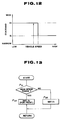
- the width of the deadband is varied between wide and narrow when the vehicle speed is varied across a predetermined vehicle speed criterion. It should be appreciated that in either case, the variation characteristics of the width of the deadband may be determined through experiments with respect to the required performance and characteristics of the vehicle to which the suspension system being installed and other factors. As will be seen from Fig. 10 , in the former case, the width of the deadband is set broader at low vehicle speed range.
- the width of the deadband is maintained constant at a predetermined maximum value.
- the width of the deadband is varied according to variation of the vehicle speed in non-linear fashion.
- the width of the deadband is maintained at a predetermined minimum width.
- the arithmetic circuit 120 may include a memory for storing the characteristics of Fig. 10 in a form of a look-up table. Table look-up may be performed in terms of the vehicle speed for deriving the deadband width.
- the width of the deadband is switched from wider width to narrower width when the vehicle speed increases across a predetermined narrower width criterion and is switched from narrower width to wider width when the vehicle speed decresses across a predetermined narrower width criterion which is set to be lower than the wider width criterion so as to provide histerisis in selection of the wide and narrower width of the deadbands.
- step P21 judgement is performed whether the vehicle speed is in a range demanding narrower width of the deadband, at a step P21 .
- check is at first performed whether the current width of the deadband is wide or narrow. If the current deadband width is wide X2 , the vehicle speed is compared with the narrower width criterion at the step P21 . On the other hand, when the current deadband width is narrow X1 , the vehicle speed is compared with the wider width criterion at the step P21 .
- the width of the deadband is set at narrower width X2 at a step P22 .
- the width of the deadband is set at wider width X1 at a step P23 .
- Fig. 13 sets the width of the deadbands for the front and rear suspension systems at different width by maintaining the deadband width of the rear system at wider width in all vehicle speed range, it may also be possible to set the width of the deadband for the rear suspension system at a value narrower than the wider width but wider than the narrower width. In the alternative, it may also be possible to use different criteria of the vehicle speed to switch the width of the deadband between wider width and narrower width.
- Fig. 14 shows another process of suspension control to be performed by the arithmetic circuit 120 for implementing another process of suspension control according to the invention.
- suspension characteristics is normally maintained at HARD mode for creating greater damping force for higher driving stability without causing degradation of the riding comfort.
- the shown process at first, read out the pressure indicative signals Sp and Ss and selects one of the pressure indicative signals depending upon the piston stroke direction, at a step P41 .
- arithmetic operation is performed for deriving the variation rate ⁇ P .
- the variation rate ⁇ P is compared with a predetermined deadband criteria for discriminating whether the variation rate is within or out of the deadband, at a step P42 .
- a HARD mode indicative flag F is reset at a step P43 .
- a HARD mode control signal is fed one of the upper and lower piezoelectric elements 60 and 90 which is selected depending upon the piston stroke direction, is fed for increasing flow restriction and thus harden damping characteristics, at a step P44 .
- process goes to END.
- the variation rate ⁇ P as checked at the step P42 is output the deadband, then check is performed whether the variation rate reaches a peak value or not at a step P45 .
- the HARD mode indicative flag F is set at a step P46 . Subsequently, the process goes to the step P44 , in which the HARD mode control signal is fed one of the upper and lower piezoelectric elements 60 and 90 which is selected depending upon the piston stroke direction, is fed for increasing flow restriction and thus harden damping characteristics. If the variation rate ⁇ P as checked at the step P45 is not the peak value, then, further check is performed at a step P47 whether the HARD mode indicative flag F is set.
- the SOFT mode control signal is fed to the corresponding one of the upper and lower piezoelectric element 60 and 90 for switching damping mode into SOFT mode at a step P48 .
- the HARD mode indicative flag F is set as checked at the step P47 , then process directly goes to END.
- suspension control is performed to maintain the damping characteristics of the shock absorber HARD mode while the variation rate ⁇ P is maintained within the deadband. This means that since judgement can be made than the vehicle is traveling on a substantially smooth road, HARD mode suspension characteristics may not cause substantial degradation of the riding comfort and may providing higher driving stability.
- the damping characteristics is maintained SOFT for effectively absorbing vibration energy.
- the damping mode is maintained at SOFT mode until the variation rate reaches the peak. After the variation rate reaches the peak, the damping mode is switched into HARD mode for effectively damping reactive motion for earlier stabilization of the vibration.
- the HARD damping mode is maintained until the variation rate varies across the deadband criteria.
- Such process may provide higher driving stability with maintaining the riding comfort at satisfactory level.
Landscapes
- Engineering & Computer Science (AREA)
- Mechanical Engineering (AREA)
- Vehicle Body Suspensions (AREA)
Claims (6)
- Système de suspension automobile comprenant : un amortisseur (1) comprenant un tube cylindrique (3) connecté à l'un d'une caisse de véhicule et d'un élément de suspension supportant à rotation une roue de voiture, et un piston (4) qui est connecté à l'autre desdites caisses de véhicule et roues de voiture, et reçu de façon coulissante dans ledit tube de cylindre de façon à diviser la cavité interne dudit tube cylindrique en des première et deuxième chambres de fluide de travail (14, 15); des moyens de communication de fluide (46,47,48,76,77) pour établir une communication de fluide entre lesdites première et deuxième chambres (14,15) avec un débit d'écoulement de fluide limité pour produire une force d'amortissement contre un mouvement relatif entre ledit piston (4) et ledit tube cylindrique (3); des moyens de soupape (74,75) associés auxdits moyens de communication de fluide pour régler la restriction à l'écoulement desdits moyens de communication de fluide pour faire varier une caractéristique d'amortissement dudit amortisseur; des moyens de détection (60,90) pour réagir à une pression de fluide dudit amortisseur et pour produire un premier signal de pression (Sp, Ss); des moyens d'actionnement (90,60) pour manipuler lesdits moyens de soupape afin de faire varier la caractéristique de restriction à l'écoulement en réponse à un signal de commande (SB, SA); et un moyen de commande (100) pour commander la caractéristique d'amortissement en produisant ledit signal de commande en accord avec le signal de pression; caractérisé en ce que ledit moyen de commande (100) détermine une vitesse de variation de la pression détectée représentée par ledit signal de pression (Sp, Ss) et fait varier la caractéristique d'amortissement vers un mode dur (P₅,P₆) lorsque ladite vitesse de variation de pression varie au-delà d'une plage basse prédéterminée (P₃) et atteint une valeur crête (P₄).
- Système de suspension automobile selon la revendication 1, caractérisé en ce que ledit moyen de commande (100) fait varier la caractéristique d'amortissement du mode dur vers le mode souple (P₇, P₈) lorsque ladite vitesse de variation de pression diminue à une valeur prédéterminée (P₃).
- Système de suspension automobile selon la revendication 2, caractérisé en ce que ladite valeur prédéterminée est égale à zéro (P₁₀).
- Système de suspension automobile selon la revendication 2, caractérisé en ce que ledit moyen de commande (100) fait varier la caractéristique d'amortissement vers le mode souple lorsque ladite vitesse de variation de pression entre dans ladite plage basse prédéterminée (P₃).
- Système de suspension automobile selon la revendication 4, caractérisé en ce que ledit moyen de détection comprend un moyen de détection de la vitesse du véhicule, et ledit moyen de commande (100) détermine ladite plage neutre en accord avec la vitesse du véhicule captée par ledit moyen de détection de la vitesse du véhicule (P₂₁, P₃₁).
- Système de suspension automobile selon l'une des revendications 1 à 5, caractérisé en ce que ledit moyen de détection comprend un premier moyen de détection de pression (60) pour détecter la pression dans la première chambre (15) et un deuxième moyen de détection de pression (90) pour détecter la pression dans la deuxième chambre (14), et lesdits moyens d'actionnement comprennent un premier moyen d'actionnement (90) pour faire varier les caractéristiques d'amortissement pendant une course de compression du piston vers le fond du tube cylindrique, et un deuxième moyen d'actionnement (60) pour faire varier les caractéristiques d'amortissement pendant une course d'expansion du piston au loin du fond du tube cylindrique, et en ce que ledit moyen de commande (100) comprend un moyen pour déterminer ladite vitesse de changement en fonction de la durée en accord avec les signaux de sortie (Sp, Ss) desdits premier et deuxième moyens de détection de pression (60,90) et pour produire des des premier et deuxième signaux de commande (SB, SA) transmis auxdits premier et deuxième moyens d'actionnement (90,60).
Applications Claiming Priority (6)
| Application Number | Priority Date | Filing Date | Title |
|---|---|---|---|
| JP53301/88 | 1988-04-19 | ||
| JP1988053301U JP2505231Y2 (ja) | 1988-04-19 | 1988-04-19 | 減衰力可変型液圧緩衝装置 |
| JP58799/88 | 1988-04-28 | ||
| JP5879988U JPH0714007Y2 (ja) | 1988-04-28 | 1988-04-28 | 減衰力可変型液圧緩衝装置 |
| JP27909288A JP2752664B2 (ja) | 1988-11-04 | 1988-11-04 | サスペンションシステム |
| JP279092/88 | 1988-11-04 |
Publications (3)
| Publication Number | Publication Date |
|---|---|
| EP0338814A2 EP0338814A2 (fr) | 1989-10-25 |
| EP0338814A3 EP0338814A3 (en) | 1990-12-12 |
| EP0338814B1 true EP0338814B1 (fr) | 1994-10-26 |
Family
ID=27294904
Family Applications (1)
| Application Number | Title | Priority Date | Filing Date |
|---|---|---|---|
| EP19890303903 Expired - Lifetime EP0338814B1 (fr) | 1988-04-19 | 1989-04-19 | Système de suspension automobile à caractéristiques de suspension variables et amortisseur variable pour dito |
Country Status (2)
| Country | Link |
|---|---|
| EP (1) | EP0338814B1 (fr) |
| DE (1) | DE68918979T2 (fr) |
Families Citing this family (4)
| Publication number | Priority date | Publication date | Assignee | Title |
|---|---|---|---|---|
| US4961483A (en) * | 1988-08-03 | 1990-10-09 | Atsugi Motor Parts, Limited | Variable damping characteristics shock absorber with feature of generation of piston stroke direction indicative signal |
| US5996745A (en) * | 1997-05-15 | 1999-12-07 | K-2 Corporation | Piezoelectric shock absorber valve |
| DE102019210578A1 (de) * | 2019-07-18 | 2021-01-21 | Zf Friedrichshafen Ag | Verstellbare Dämpfventileinrichtung mit einem Piezoaktuator |
| CN113361036B (zh) * | 2021-06-09 | 2023-04-18 | 奇瑞汽车股份有限公司 | 汽车减震器的模拟仿真方法、装置及计算机存储介质 |
Family Cites Families (6)
| Publication number | Priority date | Publication date | Assignee | Title |
|---|---|---|---|---|
| US4729459A (en) * | 1984-10-01 | 1988-03-08 | Nippon Soken, Inc. | Adjustable damping force type shock absorber |
| JPS61163011A (ja) * | 1985-01-14 | 1986-07-23 | Nissan Motor Co Ltd | 電子制御ショックアブソ−バ装置 |
| CA1263414A (fr) * | 1986-06-05 | 1989-11-28 | Magnus Lizell | Dispositif a etrangleur pour fluides de pression hydraulique dans des mecanismes amortisseurs de chocs |
| DE3632920A1 (de) * | 1986-09-27 | 1988-03-31 | Bayerische Motoren Werke Ag | Verfahren zur daempfkraftverstellung von kraftfahrzeugen |
| US4804203A (en) * | 1987-11-27 | 1989-02-14 | Ford Motor Company | Control system and method for operating adjustable vehicular suspension unit over undulating road surfaces |
| DE68919510T2 (de) * | 1988-04-14 | 1995-07-13 | Atsugi Unisia Corp | Kraftfahrzeugaufhängungssystem mit variablen Aufhängungscharakteristiken und Stossdämpfer mit veränderlicher Dämpfungskraft dafür. |
-
1989
- 1989-04-19 DE DE68918979T patent/DE68918979T2/de not_active Expired - Fee Related
- 1989-04-19 EP EP19890303903 patent/EP0338814B1/fr not_active Expired - Lifetime
Also Published As
| Publication number | Publication date |
|---|---|
| DE68918979T2 (de) | 1995-04-27 |
| EP0338814A3 (en) | 1990-12-12 |
| EP0338814A2 (fr) | 1989-10-25 |
| DE68918979D1 (de) | 1994-12-01 |
Similar Documents
| Publication | Publication Date | Title |
|---|---|---|
| US4949989A (en) | Automotive suspension system with variable suspension characteristics and variable damping force shock absorber therefor | |
| US4984819A (en) | Automotive suspension system and shock absorber therefor | |
| US5133574A (en) | Variable damping characteristics suspension system for automotive suspension system with variable damping characteristics shock absorber with input vibration frequency dependent variation characteristics | |
| US4961483A (en) | Variable damping characteristics shock absorber with feature of generation of piston stroke direction indicative signal | |
| US4948163A (en) | Damping characteristics variable hydraulic shock absorber for automotive suspension system with vehicular attitude suppressing capability | |
| US5193845A (en) | Vehicle vibration damping force control system | |
| EP0304801B1 (fr) | Jambe de suspension à taux d'amortissement variable réglé | |
| US5467280A (en) | Vehicular suspension system utilizing variable damping force shock absorber | |
| US4673194A (en) | Automotive suspension control system with self-adjustment feature | |
| US5390121A (en) | Banded on-off control method for semi-active dampers | |
| EP0255720B1 (fr) | Suspension pour véhicule | |
| EP0337797B1 (fr) | Système de suspension automobile à caractéristiques de suspension variables et amortisseur variable pour dito | |
| US6332622B1 (en) | Suspension apparatus having two interconnected shock absorbers | |
| US5054813A (en) | Rolling suppressive control system for automotive suspension system with enhanced response characteristics | |
| US5054809A (en) | Variable damping characteristics shock absorber | |
| US5521821A (en) | Suspension control system for automotive vehicle | |
| US5042832A (en) | Proportioning valve assembly and actively controlled suspension system utilizing the same | |
| KR0177352B1 (ko) | 자동차 현가 장치 제어 시스템 | |
| JPH0413568B2 (fr) | ||
| US12545070B2 (en) | Suspension system and controller | |
| US7210688B2 (en) | Suspension system for motor vehicle | |
| EP1659007B1 (fr) | Suspension pneumatique et système de suspension contrôlé électroniquement | |
| EP0338814B1 (fr) | Système de suspension automobile à caractéristiques de suspension variables et amortisseur variable pour dito | |
| US4948165A (en) | Proportioning valve assembly for an actively controlled suspension system | |
| US5048861A (en) | Active suspension system and pressure control valve therefor |
Legal Events
| Date | Code | Title | Description |
|---|---|---|---|
| PUAI | Public reference made under article 153(3) epc to a published international application that has entered the european phase |
Free format text: ORIGINAL CODE: 0009012 |
|
| AK | Designated contracting states |
Kind code of ref document: A2 Designated state(s): DE FR GB |
|
| PUAL | Search report despatched |
Free format text: ORIGINAL CODE: 0009013 |
|
| AK | Designated contracting states |
Kind code of ref document: A3 Designated state(s): DE FR GB |
|
| 17P | Request for examination filed |
Effective date: 19910605 |
|
| 17Q | First examination report despatched |
Effective date: 19920902 |
|
| RAP1 | Party data changed (applicant data changed or rights of an application transferred) |
Owner name: UNISIA JECS CORPORATION |
|
| GRAA | (expected) grant |
Free format text: ORIGINAL CODE: 0009210 |
|
| AK | Designated contracting states |
Kind code of ref document: B1 Designated state(s): DE FR GB |
|
| REF | Corresponds to: |
Ref document number: 68918979 Country of ref document: DE Date of ref document: 19941201 |
|
| ET | Fr: translation filed | ||
| PLBE | No opposition filed within time limit |
Free format text: ORIGINAL CODE: 0009261 |
|
| STAA | Information on the status of an ep patent application or granted ep patent |
Free format text: STATUS: NO OPPOSITION FILED WITHIN TIME LIMIT |
|
| 26N | No opposition filed | ||
| PGFP | Annual fee paid to national office [announced via postgrant information from national office to epo] |
Ref country code: FR Payment date: 19990409 Year of fee payment: 11 |
|
| PGFP | Annual fee paid to national office [announced via postgrant information from national office to epo] |
Ref country code: GB Payment date: 19990421 Year of fee payment: 11 |
|
| PGFP | Annual fee paid to national office [announced via postgrant information from national office to epo] |
Ref country code: DE Payment date: 19990426 Year of fee payment: 11 |
|
| PG25 | Lapsed in a contracting state [announced via postgrant information from national office to epo] |
Ref country code: GB Free format text: LAPSE BECAUSE OF NON-PAYMENT OF DUE FEES Effective date: 20000419 |
|
| GBPC | Gb: european patent ceased through non-payment of renewal fee |
Effective date: 20000419 |
|
| PG25 | Lapsed in a contracting state [announced via postgrant information from national office to epo] |
Ref country code: FR Free format text: LAPSE BECAUSE OF NON-PAYMENT OF DUE FEES Effective date: 20001229 |
|
| PG25 | Lapsed in a contracting state [announced via postgrant information from national office to epo] |
Ref country code: DE Free format text: LAPSE BECAUSE OF NON-PAYMENT OF DUE FEES Effective date: 20010201 |
|
| REG | Reference to a national code |
Ref country code: FR Ref legal event code: ST |