EP0338826A2 - Méthode et appareil pour onduler des bandes - Google Patents
Méthode et appareil pour onduler des bandes Download PDFInfo
- Publication number
- EP0338826A2 EP0338826A2 EP89303924A EP89303924A EP0338826A2 EP 0338826 A2 EP0338826 A2 EP 0338826A2 EP 89303924 A EP89303924 A EP 89303924A EP 89303924 A EP89303924 A EP 89303924A EP 0338826 A2 EP0338826 A2 EP 0338826A2
- Authority
- EP
- European Patent Office
- Prior art keywords
- web
- paddles
- chains
- paddle
- support means
- Prior art date
- Legal status (The legal status is an assumption and is not a legal conclusion. Google has not performed a legal analysis and makes no representation as to the accuracy of the status listed.)
- Granted
Links
- 238000000034 method Methods 0.000 title claims description 16
- 238000000926 separation method Methods 0.000 claims abstract description 14
- 230000001360 synchronised effect Effects 0.000 claims abstract description 7
- 239000000463 material Substances 0.000 claims description 12
- 229920001169 thermoplastic Polymers 0.000 claims description 4
- 239000004416 thermosoftening plastic Substances 0.000 claims description 4
- 238000001816 cooling Methods 0.000 claims description 2
- 238000010438 heat treatment Methods 0.000 claims 1
- 238000010276 construction Methods 0.000 description 4
- 238000009958 sewing Methods 0.000 description 3
- 239000002131 composite material Substances 0.000 description 2
- 238000009963 fulling Methods 0.000 description 2
- 239000013618 particulate matter Substances 0.000 description 2
- 239000004033 plastic Substances 0.000 description 2
- 239000000853 adhesive Substances 0.000 description 1
- 230000001070 adhesive effect Effects 0.000 description 1
- 210000004027 cell Anatomy 0.000 description 1
- 210000003850 cellular structure Anatomy 0.000 description 1
- 238000002788 crimping Methods 0.000 description 1
- 238000013461 design Methods 0.000 description 1
- 230000000694 effects Effects 0.000 description 1
- 238000004049 embossing Methods 0.000 description 1
- 230000001788 irregular Effects 0.000 description 1
- 238000012423 maintenance Methods 0.000 description 1
- 238000012986 modification Methods 0.000 description 1
- 230000004048 modification Effects 0.000 description 1
- 230000035515 penetration Effects 0.000 description 1
- 238000012545 processing Methods 0.000 description 1
- 230000000452 restraining effect Effects 0.000 description 1
- 238000007493 shaping process Methods 0.000 description 1
- 239000000126 substance Substances 0.000 description 1
- 238000003466 welding Methods 0.000 description 1
Images


Classifications
-
- B—PERFORMING OPERATIONS; TRANSPORTING
- B31—MAKING ARTICLES OF PAPER, CARDBOARD OR MATERIAL WORKED IN A MANNER ANALOGOUS TO PAPER; WORKING PAPER, CARDBOARD OR MATERIAL WORKED IN A MANNER ANALOGOUS TO PAPER
- B31F—MECHANICAL WORKING OR DEFORMATION OF PAPER, CARDBOARD OR MATERIAL WORKED IN A MANNER ANALOGOUS TO PAPER
- B31F1/00—Mechanical deformation without removing material, e.g. in combination with laminating
- B31F1/20—Corrugating; Corrugating combined with laminating to other layers
- B31F1/24—Making webs in which the channel of each corrugation is transverse to the web feed
- B31F1/30—Tools secured to endless chains, e.g. toothed belts; combined with uniting the corrugated web to flat webs
-
- Y—GENERAL TAGGING OF NEW TECHNOLOGICAL DEVELOPMENTS; GENERAL TAGGING OF CROSS-SECTIONAL TECHNOLOGIES SPANNING OVER SEVERAL SECTIONS OF THE IPC; TECHNICAL SUBJECTS COVERED BY FORMER USPC CROSS-REFERENCE ART COLLECTIONS [XRACs] AND DIGESTS
- Y10—TECHNICAL SUBJECTS COVERED BY FORMER USPC
- Y10T—TECHNICAL SUBJECTS COVERED BY FORMER US CLASSIFICATION
- Y10T156/00—Adhesive bonding and miscellaneous chemical manufacture
- Y10T156/10—Methods of surface bonding and/or assembly therefor
- Y10T156/1002—Methods of surface bonding and/or assembly therefor with permanent bending or reshaping or surface deformation of self sustaining lamina
- Y10T156/1007—Running or continuous length work
- Y10T156/1016—Transverse corrugating
- Y10T156/1021—Treating material of corrugated lamina or dry adhesive thereon to render tacky
-
- Y—GENERAL TAGGING OF NEW TECHNOLOGICAL DEVELOPMENTS; GENERAL TAGGING OF CROSS-SECTIONAL TECHNOLOGIES SPANNING OVER SEVERAL SECTIONS OF THE IPC; TECHNICAL SUBJECTS COVERED BY FORMER USPC CROSS-REFERENCE ART COLLECTIONS [XRACs] AND DIGESTS
- Y10—TECHNICAL SUBJECTS COVERED BY FORMER USPC
- Y10T—TECHNICAL SUBJECTS COVERED BY FORMER US CLASSIFICATION
- Y10T156/00—Adhesive bonding and miscellaneous chemical manufacture
- Y10T156/17—Surface bonding means and/or assemblymeans with work feeding or handling means
- Y10T156/1702—For plural parts or plural areas of single part
- Y10T156/1712—Indefinite or running length work
- Y10T156/1737—Discontinuous, spaced area, and/or patterned pressing
Definitions
- the invention relates to a method and apparatus for corrugating a flexible web and in particular to a method and apparatus for providing predetermined corrugation patterns at high speeds.
- U.S. patent No. 2,016,290 shows a pair of intermeshing toothed gears or belts used to form web corrugations in between intermeshing teeth. The web is fed in and bent around the teeth to form a wave pattern.
- U.S. Patent No. 2,350,996 discloses an apparatus having a pair of endless chains which carry tooth-like members which interengage along a straight path.
- the interengaging tooth-like members compress a web between the teeth on one chain and the teeth on the other thus providing a wavy profile to the compressed web.
- U.S. Patent No. 2,303,381 shows a sewing apparatus which is particularly directed to the sewing of neckties.
- This apparatus uses a pair of intermeshing gears to corrugate a web by feeding the web through the intermeshing gears to provide the wavy pattern to the web. The web is then fed onto a needle and pulled down by a pair of pincher rollers which bunch up the web on the needle on the downstream side of the pincher rollers.
- U.S. Patent No. 2,695,652 shows a method of treating and corrugating a unit of strip material.
- the material is fed into a bath and then drawn along two endless chains having knobs thereon which intermesh.
- the knobs provide the web with an open wavy pattern which is maintained after the web leaves the nip area between the two chains and their intermeshing knobs.
- U.S. Patent No. 2,374,033 is a reference directed to a mechanism for making neckties also. This mechanism uses a pair of crimping bands which have intermeshing teeth which fold the corrugations of a web fed therebetween in order to crepe the material for a necktie lining.
- U.S. Patent No. 2,816,520 also shows a necktie sewing machine.
- This device uses a pair of parallel chains having angle cripmers and rod crimpers which mate to crepe the lining of a necktie. The lining is then fed on a needle through openings formed in the angle crimpers.
- U.S. Patent No. 2,992,673 shows a apparatus for making cellular structures wherein pins are mounted on an endless conveyer in order to weave a pattern on a web fed therealong. The pins move into a position either above or below the web and then are moved vertically to the direction of the web to cause the web to be bent therebetween to form the internal portion of the cell structures.
- U.S. Patent No. 3,150,576 discloses feeding a web onto a moving irregular surface such that the web is blown against the surface to conform thereto. The web is then removed from the surface and maintains its structure in conformance with the moving surface on which it was laid.
- U.S. Patent No. 4,132,581 discloses an apparatus and method for forming plastic board.
- the apparatus includes the use of a corrugation forming station which forms a corrugated pattern to an internal piece of the plastic board.
- a toothed belt is synchronized with this corrugation forming station such that the teeth are received within the corrugations formed thereby.
- the corrugations are formed by a support which moves at a constant speed.
- the material must be fed onto the support and immediately takes its final shape usually by clamping the material on opposite sides by devices having the final corrugation pattern.
- These types of machines do not operate well with tight corrugations of webs, especially when tight corrugation in thicker resilient webs are desired.
- the devices are not available to make corrugations which have adjacent legs close or touching.
- Such high corrugation ratios have been left to apparatus which feed a web into a confined area where it is slowed, confined and caused to bunch up. The confines of the zone, however, limit the size of the corrugations.
- corrugation ratio is the ratio of a given length of the uncorrugated web to the length of corrugated web formed thereby.
- the apparatus comprises a pair of endless drive chains which are each made up of a series of interengaged links.
- the chains are each driven on a pair of spaced gears providing an arcuate path along a portion of the chain's path and a straight path along an other portion of the chain's path.
- the chains are spaced and parallel to one another.
- a plurality of paddles extend between the chains perpendicular to the chain path.
- the paddles are each mounted to one link of each chain in a manner that the paddle will extend perpendicularly outward from the link at all operable positions of the links. That is the paddle extends substantially radially outward as the chain travels along the arcuate portion of its path.
- Means are provided for introducing the web onto the paddles at the paddle edges opposite the chain links.
- the means introduces the web onto the paddle edge at a point where the paddle and its link are traveling about the arcuate path portion. As the paddles travel to the straight path portion the paddle ends close together and travel more slowly thus folding the web portion extending between adjacent paddles.
- a tucker wheel may be provided.
- the tucker wheel has protuberances which engage the web between the paddles and biases the web inward between adjacent paddles. This assures proper orientation of the web fold.
- An endless belt may be provided to ride along the side of the web opposite the paddle ends. This holds the web in contact with the paddles to assure proper folding and prevents sticking of the web to the protuberances of the tucker wheel.
- the method comprises movably supporting a web of material at a discrete spaced locations traveling at a given speed.
- the discrete locations are then moved toward one another by slowing a forward location and thereby permitting the next location to catch up. This closing of the locations causes the web to buckle between locations.
- the web between the descrete locations may be biased to buckle in a preferred direction as discrete locations on either side of the buckle (corrugation) close upon one another.
- the support may be provided by mechanically supporting the web at the discrete locations or by providing a belt to support the entire web length. The belt would then have discrete spaced locations which are moved together buckling the belt to form corrugations in the web.
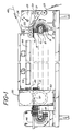
- FIG. 1 schematic overview of the apparatus of the present invention is shown. At least one pair of endless chains 10 are positioned parallel to each other. Each chain 10 is made up of a series of interengaged links 11 (FIG. 2). The links 11 pivot with respect to adjacent links to permit chain flexibility.
- the chains 10 are mounted to intermesh with and are driven by sprockets 12 (FIG. 2).
- the sprockets 12 may be fixed on the same shaft 13 thus assuring equal speed of motion in the chains 10 and proper registration.
- the chains 10 are driven by driving means such as an electric motor (not shown) driving shaft 13 in a known manner.
- driving means such as an electric motor (not shown) driving shaft 13 in a known manner.
- the chains 10 are driven along a path in the direction of arrow A.
- the path is arcuate (i.e. semicircular) about sprockets 12 and substantially straight therebetween.
- Link member 14a is substantially the same as those of known links.
- Link member 14b is modified such tht it has a perpendicularly angled extension 15.
- Link member 14b is mounted such that extension 15 is on link 11 at a radially outward position when link 11 travels about sprocket 12.
- the link in this form is readily available from chain manufacturers and is referred to as a bent attachment for a roller chain.
- extension 15 Fixed to extension 15 is a mounting block 16 which extends radially outward from extension 15.
- Block 16 is fixed to extension 15 by any known manner such as adhesives, bolting, welding, rivetting or integrally forming the two parts.
- An alternative attachment will be disclosed below in connection with FIGS. 7 and 8.
- the block 16 defines a bore 17 parallel to the link 11.
- This bore 17 has a stepped shoulder 17a and receives a bolt 18 which rests on shoulder 17a and threadedly secures the paddle 19 to block 16.
- paddle 19 is fixed in a position perpendicular to the longitudinal direction of link 11.
- the paddle will extend radially from the chain as link 11 passes around sprocket 12, moving its distal support end 20 in response to movement of link 11.
- the paddle 19 When link 11 passes around sprocket 12, the paddle 19 will fan out with respect to adjacent paddles. Thus, the support ends 20 will have a greater separation than they have when the links travel a straight line.
- the amount of the increase in separation of the support ends 20 is determined by the diameter of sprocket 12 and the radial length of the paddles 19. That is, the total distance from the axis of rotation of sprocket 12 to the support end 20.
- the block 16 defines two parallel bores 17b.
- the bores are such that their axial direction is transverse to the direction of the chain paths and parallel to the longitudinal direction of link 11.
- Each bore 17b receives a pivot pin 33.
- At least one of the pins 33 in each of the mounting blocks 16 of the embodiment shown is free to rotate in its associate bore 17b.
- Each pin 33 in block 16 either receives a fixed paddle 19 or a movable paddle 19a.
- the fixed paddle 19 is mounted at each end to a pivot pin 33 and held in a predetermined relation to mounting block 16 so it extends perpendicularly from the link 11.
- the fixed paddle 19 may be held by fixing the pivot pin 33 in bore 17b or by suitable restraining linkage.
- the movable paddle 19a is fixed to a pivot pin 33 which is free to rotate within the associated bore 17b.
- Each paddle 19, 19a is mounted in a similar fashion at its other transverse end to the other chain 10. Thus, the paddle 19, 19a extend transverse to and between the two drive chains 10 and extend perpendicularly outward from the chains 10.
- Linkage 34 is made up of a plurality of brackets 35a,35b.
- the brackets 35a,35b have an elongated shape with an opening 36 defined at a first end and a slot 37 defined at a second end.
- the slot 37 has its major dimension extending in the elongated direction of brackets 35a,35b.
- Each paddle 19,19a has mounted thereupon a linkage pin 38.
- the linkage pins 38 of adjacent paddles 19,19a are offset along the height of the paddle.
- Each linkage pin 38 is received within either the slot 37 or opening of each of two brackets 35a,35b.
- each bracket receives the linkage pin 38 of an adjacent paddle.
- the length and position of slot 37 is chosen so that the linkage pin 38 received therein is pressed against the inner end 39 of the slot 37 when the paddles connected by the bracket 35 are parallel; and the linkage pin 38 is at the outer end 40 of the slot 37 when the paddles 19,19a are fanned due to the chain passing about sprockets 12.
- adjacent linkage pins 38 By positioning adjacent linkage pins 38 in offset positions, the pin of each fixed paddle 19 is at the same position and the pin of each movable paddle 19a is the same position.
- identical brackets 35 used on all paddles 19,19a will cause the paddles to be equally spaced when fanned and when parallel.
- brackets 35 may be held at a closer distance to the fixed paddle 19 in front of it than the fixed paddle 19 behind it or vice versa.
- the difference in separation is amplified when the paddles are in the fanned position thus permitting corrugations of alternating sizes as described below.
- linkage 34 and movable paddles 19a may be omitted entirely leaving fixed paddles 19. This would produce a device having fewer paddles along the length of the chain, thus producing fewer but deeper corrugations.
- Adjacent the support end 20 of the paddle 19 is a series of hold-down belts 21 (FIG. 4).
- the hold-down belts are driven about pulleys 22.
- the web 23 to be corrugated is fed in between belts 21 and support end 20 and sandwiched therebetween.
- the web 23 need not be gripped tightly, rather the belts 21 merely prevent the web 23 from bowing out away from the paddles.
- the belts 21 often may be omitted completely.
- a tucker 24 is provided (FIG. 2).
- the tucker may be in the form of a wheel 25 having protuberances 26 extending radially therefrom.
- the wheel 25 is synchronized to the paddle 19 so a protuberance 26 is received between two adjacent paddles as the paddles close to create a corrugation.
- the protuberance 26 is removed as the paddles move to their fully closed position. At this point, holding-down belts 21 prevent protuberance 26 from pulling the web 23 out from between the paddles.
- protuberances 26 can change the characteristics of the corrugated web. By making the protuberances longer or repositioning the wheel 25 closer to the paddles the protuberances will contact the web earlier. The protuberances would then pull more of the web in before the second paddle rose to support the web. In this manner a longer portion of web is extending between the adjacent paddles thus making a deeper corrugation.
- the wheel 25 may be made adjustable by an apparatus such as that shown in FIG. 4.
- a shaft 27 on which wheel 25 rides is supported in a journal 28.
- the journal 28 is slidable along mounts 29 attached to the machine frame.
- a threaded member 30 extends from journal 28 through cleat 31 which is also attached to the machine frame. Threaded member 30 is held in cleat 31 by nuts 32. By adjusting nuts 32, the position of threaded member 30 relative the cleat 31 and therefore relative the mounts 29 may be adjusted. The change in position of threaded member 30 moves journal 28 along mounts 29 adjusting the shaft 27 and wheel 25 riding thereon.
- FIG. 10 shows in greater detail the effect of the tucker wheel 25.
- the protuberances are longer than necessary to merely initiate the folding. Therefore, the protuberances pull in an excess amount of web and hold it in position well into the folding step. This enhances operation of the device when a stiffer web is used or when a web composite of webs 23a,23b is used. This is particularly suited for holding and folding a web composite when the webs have different stiffnesses or resiliencies.
- An alternative embodiment of the tucker is shown in FIG. 11.
- a belt 42 moves adjacent the support ends 20.
- Protuberances 26 extend radially therefrom.
- web 23 forms a V-shape at point 43.
- the support ends 20 have not yet begun to close together. Therefore, the corrugations as shown in FIG. 11 are deeper than if web 23 was fed in flat and tucked between the paddles as the paddles began to close.
- an oven 44 (FIG. 12) may be positioned adjacent the web laden paddles. By using an at least partial thermoplastic web, the oven would partially melt the web causing adjacent corrugations to adhere upon cooling. This stabilizes the corrugated web for ease of handling upon removal from the apparatus by preventing separation of adjacent corrugations.
- Additional steps may be taken such as adding particulate matter to the corrugated web as the paddles are closing. Passing the web beneath the oven then adheres the tops of adjacent corrugations and compartmentalizes the particulate matter within the corrugation.
- a plurality of slots 45 are formed at the support end 20 of the paddles 19,19a.
- the slots 45 in all the paddles are aligned so as to define a channel when the paddles are parallel.
- Each channel so defined receives a wedge shaped skid 46.
- the skid 46 is preferably made of a low friction substance so the corrugated web slides easily thereon.
- the tip 47 is below the deepest penetration of web 23 between the adjacent paddles.
- the skid scoops the corrugated web up and pushes it out from between the paddles without separating the paddles. This permits the corrugations to be removed intact whereas separating the paddles may pull the corrugation tops apart tearing the bond therebetween.
- FIGS. 7-9 The preferred embodiment for ease of maintenance is shown in FIGS. 7-9 and has two pairs of spaced chains. Each pair of chains holds an alternate paddle in the series. The sprockets of one pair of chains are offset from the sprockets of the other pair by 1 ⁇ 2 pitch, that is 1 ⁇ 2 a chain link length.
- the paddles 119 and 119a have flanges 120 formed at their sides. Each of these flanges 120 defines a pair of openings 121.
- the drive chains 110 have mounting arms 122 extending from each link. These arms 122 each define a pair of openings 123 which match with openings 121.
- the openings 121,123 receive a rivet 124 which secures each paddle 119,119a to one link of each of its drive chains 110.
- the flanges 120 of paddle 119a are formed intermediate the transverse ends of the paddle 119a. In this manner the drive chains of paddle 119a are positioned in spaced relation within a central portion.
- the paddle 119a tapers in shape upward from the flanges to widen and form the support edge of full width.
- the flanges 120 of paddle 119 are formed near the transverse ends of paddle 119. In this manner the drive chains 110 of paddle 119 are positioned at the outer edge of paddle 119.
- the paddle 119 forms a central open portion defined by edge 125.
- the two pairs of endless chains are driven at the same speed and synchronized so that the paddles extend transversely to the path of the chains.
- the paddles fan out and open up.
- the paddles close back together as described above.
- the web 23 is fed onto the ends of the paddles 19 and 19a tangentially to the arc they form when fanned.
- the web is placed on the tips of the paddles when they are in their fanned position.
- the spacing of the paddle ends is the largest factor in the size of the corrugations.
- a corrugation ratio of twelve is obtained and each corrugation will be approximately three inches deep.
- the corrugation ratio may be increased. For example, if the material of the web is tucked in one inch while the paddles are spread six inches, a corrugation ratio of approximately 12.65 is obtained when the paddles close to one half inch.
- the linkage on the paddles of the alternative embodiment may be changed so the movable paddles fan closer to a fixed paddle on one side than to a fixed paddle on the opposite side of the movable paddle. In this manner, a corrugation pattern is produced where adjacent corrugations are of different depths permitting alternation of corrugation size.
- tucker wheel 25 starts the fold of the web radially inward toward the chain between support ends 20 of the paddles. This is done by the alignment of protuberances 26 to fall in between the paddles. As the paddles ride up to their straightened position, belt 21 holds the web to prevent it from bowing out from in between the paddles. As the chain straightens out, the paddles are drawn together to a parallel position. Thus, the web is folded into a corrugated condition wherein the legs of adjacent corrugations are in contact with each other. At this point, an optional cover layer 48 is introduced onto the tops of the corrugations.
- the paddles then travel beneath oven 44 which heats the web material and cover layer causing the corrugations to fuse to the cover layer. This stabilizes the corrugated web.
- the web thus stabilized is passed through hot air supplies 49 which soften the marginal portions.
- skids 46 which fit in slots 45 extend beneath the corrugated web. The forward motion of the paddles pushes the web along the inclined upper surfaces of the skids to lift the web from between the paddles and out of the apparatus for further processing.
- the softened marginal portions are compressed by embossing rolls 50 to form a unitary selvedge. This adheres the edges and prevents separation of the corrugations.
- FIGS. 13-19 novel corrugation constructions which may be fabricated by the present apparatus are shown.
- FIG. 13 shows a corrugated web having uniformly sized corrugations 51. This structure is formed by having equally spaced straight paddles and equal length protuberances on the tucker.
- FIG. 14 shows a construction formed having paddles of changing pitch. Such a variation is produced by removing three floating paddles in a row thus leaving the interleaved fixed paddles. The pitch of the paddles without the floating paddles is twice the remaining paddles and form corrugations 51a.
- FIG. 15 shows an arrangement similar to FIG. 14, however, the protuberances of the tucker are longer in the narrow separated paddles thus pulling in more material and making the narrow corrugations taller.
- FIG. 16 shows a corrugated web formed using a constant paddle pitch with the tucker of FIG. 15. Thus, a constant corrugation thickness is obtained with a varying corrugation height.
- FIG. 17 shows a construction formed using a tucker wheel that has smoothly varying protuberance length.
- FIGS. 18 and 19 show corrugation patterns obtained by shaping the paddles. A wavey edge on the paddle produces the pattern of FIG. 18. If adjacent paddles are made to meet at wave peaks, it may be possible to bond adjacent corrugations 51 at the points 52 where the patterns meet.
- FIG. 19 shows the corrugation pattern created by slightly bowed paddles.
Landscapes
- Engineering & Computer Science (AREA)
- Mechanical Engineering (AREA)
- Machines For Manufacturing Corrugated Board In Mechanical Paper-Making Processes (AREA)
- Folding Of Thin Sheet-Like Materials, Special Discharging Devices, And Others (AREA)
- Shaping Of Tube Ends By Bending Or Straightening (AREA)
- Advancing Webs (AREA)
- Preliminary Treatment Of Fibers (AREA)
- Treatment Of Fiber Materials (AREA)
- Coating With Molten Metal (AREA)
Priority Applications (1)
| Application Number | Priority Date | Filing Date | Title |
|---|---|---|---|
| AT89303924T ATE97058T1 (de) | 1988-04-21 | 1989-04-20 | Verfahren und vorrichtung zum wellen von bahnen. |
Applications Claiming Priority (2)
| Application Number | Priority Date | Filing Date | Title |
|---|---|---|---|
| US184516 | 1988-04-21 | ||
| US07/184,516 US4874457A (en) | 1988-04-21 | 1988-04-21 | Web corrugating apparatus |
Publications (3)
| Publication Number | Publication Date |
|---|---|
| EP0338826A2 true EP0338826A2 (fr) | 1989-10-25 |
| EP0338826A3 EP0338826A3 (fr) | 1991-01-16 |
| EP0338826B1 EP0338826B1 (fr) | 1993-11-10 |
Family
ID=22677208
Family Applications (1)
| Application Number | Title | Priority Date | Filing Date |
|---|---|---|---|
| EP89303924A Expired - Lifetime EP0338826B1 (fr) | 1988-04-21 | 1989-04-20 | Méthode et appareil pour onduler des bandes |
Country Status (10)
| Country | Link |
|---|---|
| US (1) | US4874457A (fr) |
| EP (1) | EP0338826B1 (fr) |
| AT (1) | ATE97058T1 (fr) |
| AU (1) | AU613474B2 (fr) |
| BR (1) | BR8901882A (fr) |
| CA (1) | CA1321459C (fr) |
| DE (1) | DE68910567T2 (fr) |
| GR (1) | GR1000726B (fr) |
| NZ (1) | NZ228699A (fr) |
| ZA (1) | ZA892921B (fr) |
Cited By (4)
| Publication number | Priority date | Publication date | Assignee | Title |
|---|---|---|---|---|
| EP0841154A1 (fr) * | 1996-11-12 | 1998-05-13 | Onduline S.A. | Machine pour reprofiler des matériaux ondulés |
| FR2755640A1 (fr) * | 1996-11-12 | 1998-05-15 | Onduline Sa | Machine ondulatrice |
| WO2004098867A1 (fr) * | 2003-05-08 | 2004-11-18 | Interwave S.R.L. | Machine automatique de production d'elements de type feuille ondulee destines notamment a l'emballage, l'isolation thermique, l'isolation phonique et analogue |
| FR2900419A1 (fr) * | 2006-04-26 | 2007-11-02 | Schlumberger Sa N | Procede de fabrication de non-tisse en trois dimensions, ligne de fabrication pour la mise en oeuvre de ce procede et produit non-tisse en trois dimensions obtenu |
Families Citing this family (17)
| Publication number | Priority date | Publication date | Assignee | Title |
|---|---|---|---|---|
| US5753343A (en) * | 1992-08-04 | 1998-05-19 | Minnesota Mining And Manufacturing Company | Corrugated nonwoven webs of polymeric microfiber |
| US5505719A (en) | 1994-06-30 | 1996-04-09 | Mcneil-Ppc, Inc. | Multilayered absorbent structures |
| US5814390A (en) | 1995-06-30 | 1998-09-29 | Kimberly-Clark Worldwide, Inc. | Creased nonwoven web with stretch and recovery |
| IT1298011B1 (it) | 1997-07-11 | 1999-12-20 | Agnati Spa | Gruppo ondulare, in particolare per fogli o nastri di materiale cartaceo, o simili. |
| US20010009711A1 (en) * | 1998-12-16 | 2001-07-26 | Margaret Gwyn Latimer | Resilient fluid management materials for personal care products |
| EP1110523A1 (fr) * | 1999-12-23 | 2001-06-27 | The Procter & Gamble Company | Système de traitement de liquide avec une membrane à trois dimensions |
| US6488670B1 (en) * | 2000-10-27 | 2002-12-03 | Kimberly-Clark Worldwide, Inc. | Corrugated absorbent system for hygienic products |
| US20030236512A1 (en) * | 2002-06-19 | 2003-12-25 | Baker Andrew A. | Absorbent core with folding zones for absorbency distribution |
| US7883497B2 (en) * | 2003-02-28 | 2011-02-08 | Sca Hygiene Products Ab | Absorbent article including an absorbent structure |
| CN101668576B (zh) | 2007-02-28 | 2013-07-24 | 霍林斯沃思和沃斯有限公司 | 波形过滤介质和元件 |
| US8257459B2 (en) | 2007-02-28 | 2012-09-04 | Hollingsworth & Vose Company | Waved filter media and elements |
| US8202340B2 (en) * | 2007-02-28 | 2012-06-19 | Hollingsworth & Vose Company | Waved filter media and elements |
| US8104320B2 (en) * | 2008-02-15 | 2012-01-31 | The Boeing Company | Method and apparatus for corrugating sheet metal |
| US10441909B2 (en) | 2014-06-25 | 2019-10-15 | Hollingsworth & Vose Company | Filter media including oriented fibers |
| DE102015108651A1 (de) * | 2015-06-01 | 2016-12-01 | Technische Universität Berlin | Verfahren und Vorrichtung zum z-Falten eines Bahnmaterials |
| US10449474B2 (en) | 2015-09-18 | 2019-10-22 | Hollingsworth & Vose Company | Filter media including a waved filtration layer |
| US10561972B2 (en) | 2015-09-18 | 2020-02-18 | Hollingsworth & Vose Company | Filter media including a waved filtration layer |
Family Cites Families (27)
| Publication number | Priority date | Publication date | Assignee | Title |
|---|---|---|---|---|
| US568307A (en) * | 1896-09-22 | Machine for folding paper | ||
| US230091A (en) * | 1880-07-13 | William walkeb | ||
| DE364381C (de) * | 1922-11-23 | Richard Schneid | Wellpappe | |
| FR361559A (fr) * | 1905-06-16 | 1906-09-13 | Fr De L Ondulium Soc | Système de tables mobiles à chaine pour machines diverses |
| US1290800A (en) * | 1916-04-21 | 1919-01-07 | Tissue Company | Apparatus for folding and interleaving paper sheets. |
| US1944280A (en) * | 1927-04-26 | 1934-01-23 | Guardian Trust Company | Fabricated board |
| US1903618A (en) * | 1928-05-16 | 1933-04-11 | Nat Automotive Fibres Inc | Plait forming apparatus |
| US1989690A (en) * | 1932-09-12 | 1935-02-05 | Goodrich Co B F | Apparatus for looping sheet material |
| US2636250A (en) * | 1942-12-10 | 1953-04-28 | Sandoz Ltd | Process for the production of crimped fibers, filaments, and threads |
| US2513777A (en) * | 1947-12-09 | 1950-07-04 | Chrysler Corp | Apparatus for sinuous contoured material |
| US2525202A (en) * | 1948-01-08 | 1950-10-10 | Bossi Alfred | Machine for the production of packaging inlays |
| US2831525A (en) * | 1955-03-24 | 1958-04-22 | Du Pont | Tufter |
| FR1128896A (fr) * | 1955-07-20 | 1957-01-11 | Packmat A G | Procédé et machine pour onduler des bandes de carton ou autre matériel |
| CH357962A (it) * | 1957-09-17 | 1961-10-31 | Negri Scatole S R L | Dispositivo per ondulare asimmetricamente strisce di cartone e simili |
| US3157551A (en) * | 1957-09-17 | 1964-11-17 | Granozio Eurico | Apparatus for producing asymmetrically corrugated strips of cardboard, and the like |
| US3227592A (en) * | 1959-04-02 | 1966-01-04 | Celanese Corp | Shaping of non-woven batts |
| FR1294625A (fr) * | 1961-07-11 | 1962-05-26 | Machine pour la confection de matériau d'emballage comportant une bande de carton ondulée | |
| BE626594A (fr) * | 1961-12-28 | |||
| US3311524A (en) * | 1963-08-29 | 1967-03-28 | Marenta A G | Machines for producing packaging components |
| GB1091565A (en) * | 1964-05-05 | 1967-11-22 | William Donald Mcalpine | Apparatus for coating a material with a molten thermoplastic material |
| US3723213A (en) * | 1970-08-18 | 1973-03-27 | Rohm & Haas | Method of making non-woven pile fabric |
| US3785914A (en) * | 1971-07-08 | 1974-01-15 | H King | Structural material and means and method for making it |
| US3905857A (en) * | 1973-03-08 | 1975-09-16 | Deering Milliken Res Corp | Bonded carpet machine |
| SE401340B (sv) * | 1974-06-28 | 1978-05-02 | Tetra Pak Dev | Don for formning av en forpackningsmaterialbana i en forpackningsmaskin |
| DE2803079C2 (de) * | 1978-01-25 | 1984-12-06 | SIPRA Patententwicklungs-und Beteiligungsgesellschaft mbH, 7000 Stuttgart | Vorrichtung zum mechanischen Krumpfen einer Textilbahn |
| DE2851007C3 (de) * | 1978-11-24 | 1982-02-04 | BHS-Bayerische Berg-, Hütten- und Salzwerke AG, 8000 München | Vorrichtung zur Herstellung einer wenigstens einseitig deckbelegten Wellpappe |
| SU903216A1 (ru) * | 1980-05-15 | 1982-02-07 | Северный Филиал Всесоюзного Научно-Исследовательского Института По Строительству Магистральных Трубопроводов | Способ изготовлени конструкционного чеистого материала |
-
1988
- 1988-04-21 US US07/184,516 patent/US4874457A/en not_active Expired - Lifetime
-
1989
- 1989-04-11 NZ NZ228699A patent/NZ228699A/xx unknown
- 1989-04-13 AU AU32786/89A patent/AU613474B2/en not_active Expired
- 1989-04-18 GR GR890100257A patent/GR1000726B/el not_active IP Right Cessation
- 1989-04-19 CA CA000597116A patent/CA1321459C/fr not_active Expired - Fee Related
- 1989-04-20 DE DE89303924T patent/DE68910567T2/de not_active Expired - Lifetime
- 1989-04-20 ZA ZA892921A patent/ZA892921B/xx unknown
- 1989-04-20 AT AT89303924T patent/ATE97058T1/de not_active IP Right Cessation
- 1989-04-20 EP EP89303924A patent/EP0338826B1/fr not_active Expired - Lifetime
- 1989-04-20 BR BR898901882A patent/BR8901882A/pt not_active IP Right Cessation
Cited By (10)
| Publication number | Priority date | Publication date | Assignee | Title |
|---|---|---|---|---|
| EP0841154A1 (fr) * | 1996-11-12 | 1998-05-13 | Onduline S.A. | Machine pour reprofiler des matériaux ondulés |
| FR2755639A1 (fr) * | 1996-11-12 | 1998-05-15 | Onduline Sa | Machine pour reprofiler des materiaux ondules |
| FR2755640A1 (fr) * | 1996-11-12 | 1998-05-15 | Onduline Sa | Machine ondulatrice |
| EP0844071A1 (fr) * | 1996-11-12 | 1998-05-27 | Onduline S.A. | Machine ondulatrice |
| US5858418A (en) * | 1996-11-12 | 1999-01-12 | Onduline | Machine for reprofiling corrugated materials |
| US6042359A (en) * | 1996-11-12 | 2000-03-28 | Onduline | Corrugating machine |
| WO2004098867A1 (fr) * | 2003-05-08 | 2004-11-18 | Interwave S.R.L. | Machine automatique de production d'elements de type feuille ondulee destines notamment a l'emballage, l'isolation thermique, l'isolation phonique et analogue |
| CN1784299B (zh) * | 2003-05-08 | 2012-04-04 | 英特威武有限责任公司 | 生产尤其用于包装、绝热、隔音等的波纹板状元件的自动化机器 |
| FR2900419A1 (fr) * | 2006-04-26 | 2007-11-02 | Schlumberger Sa N | Procede de fabrication de non-tisse en trois dimensions, ligne de fabrication pour la mise en oeuvre de ce procede et produit non-tisse en trois dimensions obtenu |
| WO2007125248A3 (fr) * | 2006-04-26 | 2007-12-27 | Schlumberger Soc Par Actions S | Procede de fabrication de non-tisse en trois dimensions, ligne de fabrication pour la mise en oeuvre de ce procede et produit non-tisse en trois dimensions obtenu |
Also Published As
| Publication number | Publication date |
|---|---|
| DE68910567D1 (de) | 1993-12-16 |
| CA1321459C (fr) | 1993-08-24 |
| GR1000726B (el) | 1992-11-23 |
| DE68910567T2 (de) | 1994-04-07 |
| US4874457A (en) | 1989-10-17 |
| ATE97058T1 (de) | 1993-11-15 |
| EP0338826B1 (fr) | 1993-11-10 |
| EP0338826A3 (fr) | 1991-01-16 |
| ZA892921B (en) | 1990-12-28 |
| AU613474B2 (en) | 1991-08-01 |
| AU3278689A (en) | 1989-10-26 |
| GR890100257A (en) | 1990-01-31 |
| NZ228699A (en) | 1991-09-25 |
| BR8901882A (pt) | 1990-04-10 |
Similar Documents
| Publication | Publication Date | Title |
|---|---|---|
| US4874457A (en) | Web corrugating apparatus | |
| US5868539A (en) | Process and device for the manufacture of a book | |
| US3902710A (en) | Accordion, folding and cutting apparatus | |
| CA1200804A (fr) | Separateur mecanique de tubes en papier perfores | |
| JP3041310B2 (ja) | 紙ナプキンまたは同様な物品を製造するための装置及び方法 | |
| US4498944A (en) | Method and apparatus for producing an elasticized garment by tucking a portion of the diaper web during bonding of elastic to the untucked portions of the web | |
| JPH10500074A (ja) | 包装材料製造装置 | |
| JPH04246538A (ja) | 書籍−及びカレンダー印刷用の輪転印刷機 | |
| JP5587668B2 (ja) | 延伸試験装置および延伸試験方法 | |
| US3557156A (en) | Sectional drive apparatus for continuously feeding an elastic material | |
| EP0514158B1 (fr) | Appareil et procédé de manipulation et d'orientation de feuilles de pâte | |
| US7770368B2 (en) | Enveloping device | |
| GB2217673A (en) | Packaging apparatus | |
| WO2003084849A1 (fr) | Appareil de pliage transversal | |
| JP5826558B2 (ja) | 皺伸ばし装置 | |
| US4549729A (en) | Overlap conveyor apparatus | |
| US3904186A (en) | Accordion, folding and cutting apparatus | |
| JP5324950B2 (ja) | 長尺印刷物の筋折り付きジグザグ折り装置 | |
| CN1240402A (zh) | 弯折料段的装置 | |
| JPH01114489A (ja) | 本の成型、溝付け、及び全圧締の方法及びその機械 | |
| US4102531A (en) | Method of and apparatus for folding a sheet to form pages of variable format | |
| CA2451331C (fr) | Methode et dispositif d'emballage d'objets plats | |
| JP2511989B2 (ja) | シ−ト状物の同時二軸延伸方法 | |
| US4061458A (en) | Apparatus for processing a web of material without a standstill | |
| FI3854569T3 (fi) | Venytyslaite synteettisestä materiaalista valmistetun kalvon venyttämiseksi |
Legal Events
| Date | Code | Title | Description |
|---|---|---|---|
| PUAI | Public reference made under article 153(3) epc to a published international application that has entered the european phase |
Free format text: ORIGINAL CODE: 0009012 |
|
| AK | Designated contracting states |
Kind code of ref document: A2 Designated state(s): AT BE CH DE FR GB IT LI LU NL SE |
|
| PUAL | Search report despatched |
Free format text: ORIGINAL CODE: 0009013 |
|
| AK | Designated contracting states |
Kind code of ref document: A3 Designated state(s): AT BE CH DE FR GB IT LI LU NL SE |
|
| 17P | Request for examination filed |
Effective date: 19910625 |
|
| 17Q | First examination report despatched |
Effective date: 19920514 |
|
| GRAA | (expected) grant |
Free format text: ORIGINAL CODE: 0009210 |
|
| AK | Designated contracting states |
Kind code of ref document: B1 Designated state(s): AT BE CH DE FR GB IT LI LU NL SE |
|
| REF | Corresponds to: |
Ref document number: 97058 Country of ref document: AT Date of ref document: 19931115 Kind code of ref document: T |
|
| REF | Corresponds to: |
Ref document number: 68910567 Country of ref document: DE Date of ref document: 19931216 |
|
| ET | Fr: translation filed | ||
| ITF | It: translation for a ep patent filed | ||
| EPTA | Lu: last paid annual fee | ||
| PLBE | No opposition filed within time limit |
Free format text: ORIGINAL CODE: 0009261 |
|
| STAA | Information on the status of an ep patent application or granted ep patent |
Free format text: STATUS: NO OPPOSITION FILED WITHIN TIME LIMIT |
|
| 26N | No opposition filed | ||
| EAL | Se: european patent in force in sweden |
Ref document number: 89303924.8 |
|
| REG | Reference to a national code |
Ref country code: GB Ref legal event code: IF02 |
|
| REG | Reference to a national code |
Ref country code: CH Ref legal event code: PFA Owner name: MCNEIL-PPC INC. Free format text: MCNEIL-PPC INC.#VAN LIEW AVENUE#MILLTOWN/NJ (US) -TRANSFER TO- MCNEIL-PPC INC.#VAN LIEW AVENUE#MILLTOWN/NJ (US) |
|
| PGFP | Annual fee paid to national office [announced via postgrant information from national office to epo] |
Ref country code: DE Payment date: 20080424 Year of fee payment: 20 Ref country code: FR Payment date: 20080312 Year of fee payment: 20 Ref country code: LU Payment date: 20080513 Year of fee payment: 20 Ref country code: CH Payment date: 20080502 Year of fee payment: 20 |
|
| PGFP | Annual fee paid to national office [announced via postgrant information from national office to epo] |
Ref country code: AT Payment date: 20080410 Year of fee payment: 20 |
|
| PGFP | Annual fee paid to national office [announced via postgrant information from national office to epo] |
Ref country code: IT Payment date: 20080428 Year of fee payment: 20 Ref country code: BE Payment date: 20080616 Year of fee payment: 20 |
|
| PGFP | Annual fee paid to national office [announced via postgrant information from national office to epo] |
Ref country code: NL Payment date: 20080303 Year of fee payment: 20 Ref country code: SE Payment date: 20080408 Year of fee payment: 20 |
|
| PGFP | Annual fee paid to national office [announced via postgrant information from national office to epo] |
Ref country code: GB Payment date: 20080423 Year of fee payment: 20 |
|
| BE20 | Be: patent expired |
Owner name: *MCNEIL-PPC INC. Effective date: 20090420 |
|
| REG | Reference to a national code |
Ref country code: CH Ref legal event code: PL |
|
| REG | Reference to a national code |
Ref country code: GB Ref legal event code: PE20 Expiry date: 20090419 |
|
| PG25 | Lapsed in a contracting state [announced via postgrant information from national office to epo] |
Ref country code: NL Free format text: LAPSE BECAUSE OF EXPIRATION OF PROTECTION Effective date: 20090420 |
|
| NLV7 | Nl: ceased due to reaching the maximum lifetime of a patent |
Effective date: 20090420 |
|
| EUG | Se: european patent has lapsed | ||
| PG25 | Lapsed in a contracting state [announced via postgrant information from national office to epo] |
Ref country code: GB Free format text: LAPSE BECAUSE OF EXPIRATION OF PROTECTION Effective date: 20090419 |