EP0338880A1 - Verbindungseinrichtung zwischen einem schlauchartigen Verbindungsteil und einem starren Rohrende für einen Druckmittelkreislauf - Google Patents
Verbindungseinrichtung zwischen einem schlauchartigen Verbindungsteil und einem starren Rohrende für einen Druckmittelkreislauf Download PDFInfo
- Publication number
- EP0338880A1 EP0338880A1 EP89400889A EP89400889A EP0338880A1 EP 0338880 A1 EP0338880 A1 EP 0338880A1 EP 89400889 A EP89400889 A EP 89400889A EP 89400889 A EP89400889 A EP 89400889A EP 0338880 A1 EP0338880 A1 EP 0338880A1
- Authority
- EP
- European Patent Office
- Prior art keywords
- flexible connector
- end piece
- rigid
- rigid end
- flexible
- Prior art date
- Legal status (The legal status is an assumption and is not a legal conclusion. Google has not performed a legal analysis and makes no representation as to the accuracy of the status listed.)
- Granted
Links
Images

Classifications
-
- F—MECHANICAL ENGINEERING; LIGHTING; HEATING; WEAPONS; BLASTING
- F16—ENGINEERING ELEMENTS AND UNITS; GENERAL MEASURES FOR PRODUCING AND MAINTAINING EFFECTIVE FUNCTIONING OF MACHINES OR INSTALLATIONS; THERMAL INSULATION IN GENERAL
- F16L—PIPES; JOINTS OR FITTINGS FOR PIPES; SUPPORTS FOR PIPES, CABLES OR PROTECTIVE TUBING; MEANS FOR THERMAL INSULATION IN GENERAL
- F16L33/00—Arrangements for connecting hoses to rigid members; Rigid hose-connectors, i.e. single members engaging both hoses
- F16L33/16—Arrangements for connecting hoses to rigid members; Rigid hose-connectors, i.e. single members engaging both hoses with sealing or securing means using fluid pressure
Definitions
- the invention relates to a junction device between a flexible tubular connection and a rigid tubular end piece, in a circuit containing a pressurized fluid in service.
- Modern motor vehicles have an increasingly tapered hood for improving the vehicle's C X.
- the space available under the hood for the radiator is therefore reduced compared to older vehicles.
- the water in the cooling system is therefore relatively less cooled on modern vehicles. This water is found, during the running of the vehicle, at a pressure and at a temperature which is appreciably greater than the pressure and the temperature of the water in the cooling circuits of older vehicles.
- connection conduits or flexible fittings have been engaged on the corresponding rigid end piece and fixed in leaktight manner on this end piece by means of a clamping collar placed around the flexible end piece.
- the cable ties used can be of different types.
- the object of the invention is therefore to propose a junction device between a flexible tubular connection and a rigid tubular end piece in a circuit containing in service a pressurized fluid such as the cooling circuit of a motor vehicle, this device ensuring a watertight fixing of the flexible connector on the end piece, while being of a simple structure and requiring no complex assembly operation.
- the junction device consists of an end portion of the flexible connector inserted inside the rigid end piece, the wall of the flexible connector subjected in service to the pressure of the fluid on its surface. internal being in sealed contact, through its external surface, with the internal surface of the rigid end piece.
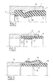
- FIG. 1 there is shown an end portion of a rigid tubular end piece 1 which may for example be integral with the radiator or the engine of a motor vehicle.
- This end piece 1 is machined internally, in its end part, so as to produce an annular housing terminated by a shoulder 3, in the thickness of the wall of the end piece.
- the internal machining of the end piece also makes it possible to provide an annular part 2 projecting radially inside the annular housing.
- This radial projecting part 2 is delimited by a radial shoulder and by a frustoconical surface 2a directed towards the open end of the end piece 1.
- a flexible connector 4 for example made of rubber
- the end part of a flexible connector 4 is introduced into the annular housing of the end piece 1, until its end comes to bear on the shoulder 3.
- the flexible connector 4 is deformed in the radial direction and inwards, which allows it to pass at the level of the projecting part 2.
- an elastic ring 5 which may consist of a split metal ring is placed inside the flexible connector 4, at its end. Ring 5 avoids sagging of the connection and to guarantee a certain maintenance of this flexible connection 4 inside the rigid end piece 1, in the absence of pressure in the cooling circuit.
- the internal overpressure of the flexible connector 4 causes the flexible connector 4 to deform outward in the radial direction, so that the external surface of the flexible connector 4 is applied against the inner surface of the rigid tip 1.
- the seal between the fitting 4 and the rigid end piece 1 is ensured along the frustoconical surface 2a and along the cylindrical surface 1a constituting the entry portion of the bore of the rigid end piece 1, the external surface of the flexible fitting 4 being brought into leaktight contact and pressed against these surfaces, by the overpressure of the fluid contained in the flexible connector.
- a positioning mark 7 which can be constituted for example by a trace of paint on the part of the flexible connector 4 coming to be placed in agreement with the end of the rigid end piece 1 makes it possible to verify the correct positioning of the flexible connector 4 inside the rigid end piece 1 during assembly.
- the tightness of the junction increases with the pressure of application of the flexible connector on the internal surface of the end piece, that is to say with the pressure of the cooling fluid in the circuit.
- FIG. 2 an alternative embodiment of a junction device according to the invention is seen, the end of the flexible connector 8 engaged in the end part of the rigid end piece 10 having hollow parts 9 of shaped annular and the rigid end piece 10 comprising on its inner surface annular projecting parts 10 coming to be placed inside the annular cavities 9, when the flexible connector 8 is engaged in the rigid end piece 10.
- An elastic ring 12 for holding the flexible connector 8 is engaged in the end part of the flexible connector 8.
- junction device shown in FIG. 2 makes it possible to avoid any axial displacement of the flexible connector 8 inside the rigid end piece 10, after its installation, even in the case where the cooling circuit and the interior volume of the flexible connector 8 are not under pressure.
- the pressurization of the cooling circuit makes it possible to apply the external surface of the wall of the flexible connector 8 against the internal surface of the rigid end piece 10, which makes it possible to obtain good sealing of the junction.
- FIG. 3 a second variant of a junction device according to the invention is shown, the flexible connector 13 comprising an external skirt 14 coaxial with the tubular part of the connector 13, made of material and directed towards the end of the connection.
- the connector 13 further comprises an annular cavity 15 into which engages a portion 17 of the rigid endpiece 16 of annular shape and machined projecting from the inner surface of this endpiece 16. This ensures the establishment and axial retention of the connector 13 inside the rigid end piece 16, after its installation.
- the fixing of the connector 13 is completed by a collar 18 ensuring the tightening of the skirt 14 against the external surface of the rigid end piece 16.
- the flexible connection 13 is thus held in position on the rigid end piece 16, even in the absence pressure in the cooling circuit.
- the pressure of the coolant acting inside the fitting flexible 13 allows pressure to be exerted on the wall of the connector, the external surface of which is applied in a sealed manner to the internal surface of the rigid endpiece 16.
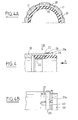
- FIGS. 4, 4A and 4B an alternative embodiment of the joining device is shown, the end of the rigid end piece 19 comprising slots 20 delimiting tongues 21 elastically deformable by bending.
- the rigid end piece 19 also comprises a part 22 of annular shape projecting radially inwards ensuring the retention of the flexible connector 24 when the latter is introduced into the rigid end piece 19, by radial deformation.
- the flexible connector 24 also includes an elastic retaining ring 25 which may be constituted by a split ring inserted in its end part.
- a sliding clamping ring 26 is threaded on the external surface of the rigid end piece 19 and can come into a clamping position, as shown in FIGS. 4 and 4B in which the ring 26 ensures the folding of the tongues 21 inwards and the deformation of the flexible connector 24 by means of the projecting parts 26 of the tongues 21.
- the sliding ring 26 can be moved by sliding between its clamping position and a position where the ring 26 is no longer in contact with the tongues 21. In this second position of the ring 26, the tongues 21 are spread outwards in radial directions and provide a passage at their central part for introducing the end of the flexible connector 24 without difficulty.
- the tubular end piece 19 constitutes at its end part an annular housing for the end of the flexible connector 24, over a length corresponding to the tongues 21 and to an unsplit area of the rigid end piece 19 situated in the extension of the tongues 21
- the tightness of the junction is ensured by bringing the end of the flexible connector 24 into contact with this non-split zone of the rigid end piece 19, under the effect of the pressure of the cooling fluid in the circuit.
- Each of the tongues 21 has a rim 21a projecting towards the outside, making it possible to prevent the sliding ring 26 from leaving the end of the rigid end piece 19.
- the joining device shown in FIG. 5 comprises a rigid tubular end piece 30 having an O-shaped cavity 31 machined on its interior surface.
- the end portion of the flexible connector 34 comprises a bead 33 of toroidal shape coming to engage in the annular cavity 31, during the positioning of the flexible connector 34 in the rigid end piece 30.
- An elastic ring 32 is engaged to inside the flexible connector 34, at its end.
- the O-ring bead 33 ensures the axial retention of the flexible connector 34 in the rigid end piece 30.
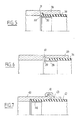
- FIG. 6 shows the end of a rigid end piece 35 machined internally to receive the end part of the flexible connector 36 and to constitute an annular cavity for axial retention of the flexible connector 36.
- the flexible connector 36 is integral at its end with a ring 38 having an end portion 39 projecting radially outward, relative to the ring 38 and relative to the flexible connector 36.
- the ring 38 is fixed inside the flexible connector 36, by gluing or crimping.
- the projecting part 39 is placed inside the annular cavity 37 and thus ensures the axial retention of the flexible connector. 36 inside the rigid end piece 35.
- the ring 38 also makes it possible to keep the end of the flexible connector 36 not deformed in the absence of pressure, inside the cooling circuit.
- a rigid end piece 40 is seen comprising an end portion projecting radially outwards 41 allowing the attachment and retention of a flexible connector 42 engaged inside the rigid end piece, by by means of an annular attachment piece 43.
- the piece 43 is fixed to the external surface of the flexible connector 42, by gluing or by crimping.
- An elastic ring 44 fixed inside the flexible connector 42 makes it possible to avoid deformation of the flexible connector 42 by radial collapse, when the cooling circuit is not under pressure.
- the tightness of the junction is ensured by bringing the external surface of the wall of the flexible connector 42 into contact with pressure with the internal surface of the rigid end piece 40.
- FIGS. 8 and 8A we see a rigid tubular end piece 45 machined internally to delimit an annular housing in which the flexible connector 46 is placed.
- the rigid end piece 45 also has at its end an extension 47 delimiting a closed cavity 48 by a flange 47a.
- the flexible connector 46 has a radial projecting portion of annular shape made of material 46a intended to engage in mounting in the cavity 48. This thus ensures the axial retention of the flexible connector 46 in the rigid end piece 45.
- An elastic ring 49 placed inside the flexible connector 46 avoids the deformation of the end of the flexible connector 46, in the absence of pressure in the cooling circuit.
- FIGS. 9 and 9A we see a rigid tubular end piece 50 machined externally to constitute a cavity 51 of annular shape delimited by a flange 52.
- the flexible connector 53 comprises a part projecting radially towards the outside 53a made of material, the diameter is greater than the inside diameter of the rigid end piece 50.
- An elastic ring 54 constituted by a split ring is engaged in the end part of the flexible connector 53 of which it prevents deformation in the absence of pressure.
- the flexible connector 53 is mounted on the rigid connector 50 by engaging the end of the flexible connector 53 in the rigid connector 50, as shown in FIG. 9.
- the axial retention of the flexible connector 53 in the rigid end piece 50 is ensured by means of a ring 55 in two parts 55a and 55b clipped one on the other by their ends comprising complementary assembly elements.
- the rider-shaped transverse profile of the ring 55 visible in FIG. 9 ensures the axial retention of the flexible connector 53 relative to the rigid end piece 50.
- the ring 55 has flanges 56 and 57 of radial direction and directed towards the inside.
- the two parts 55a and 55b of the ring 55 are engaged laterally on the rigid end piece and on the flexible connection, so that the flange 56 is engaged in the closed cavity 51 by the rim 52.
- the ring 55 is assembled by clipping, the projecting part 53a of the flexible connector 53 being disposed inside the ring 55 and held in axial position by the rim 57.
- the junction of the flexible conduit and the rigid end piece is carried out in a simple manner by engagement of the flexible connection inside the rigid end piece.
- This engagement can be achieved by force or by simple sliding, an axial locking element of the flexible connector being then put in place.
- the tightness which is ensured thanks to the pressurization of the fluid in the circuit is all the better the higher the pressure of the fluid.
- the flexible connector may include corresponding hollow or projecting hooking parts of any shape.
- the invention applies to any circuit intended to receive a pressurized fluid in service and comprising flexible connectors, for example rubber, which are assembled to rigid tubular end pieces.
Landscapes
- Engineering & Computer Science (AREA)
- General Engineering & Computer Science (AREA)
- Mechanical Engineering (AREA)
- Quick-Acting Or Multi-Walled Pipe Joints (AREA)
Applications Claiming Priority (2)
| Application Number | Priority Date | Filing Date | Title |
|---|---|---|---|
| FR8805305A FR2630522B1 (fr) | 1988-04-21 | 1988-04-21 | Dispositif de jonction entre un raccord souple et un embout tubulaire rigide d'un circuit contenant un fluide sous pression |
| FR8805305 | 1988-04-21 |
Publications (2)
| Publication Number | Publication Date |
|---|---|
| EP0338880A1 true EP0338880A1 (de) | 1989-10-25 |
| EP0338880B1 EP0338880B1 (de) | 1991-12-04 |
Family
ID=9365536
Family Applications (1)
| Application Number | Title | Priority Date | Filing Date |
|---|---|---|---|
| EP19890400889 Expired - Lifetime EP0338880B1 (de) | 1988-04-21 | 1989-03-30 | Verbindungseinrichtung zwischen einem schlauchartigen Verbindungsteil und einem starren Rohrende für einen Druckmittelkreislauf |
Country Status (3)
| Country | Link |
|---|---|
| EP (1) | EP0338880B1 (de) |
| DE (1) | DE68900491D1 (de) |
| FR (1) | FR2630522B1 (de) |
Cited By (7)
| Publication number | Priority date | Publication date | Assignee | Title |
|---|---|---|---|---|
| US5211429A (en) * | 1991-09-09 | 1993-05-18 | Charlson Norman E | Polyethylene pipe junction device |
| DE19639055A1 (de) * | 1996-09-24 | 1998-04-02 | Kaercher Gmbh & Co Alfred | Hochdruckschlauch mit einer Armatur zum Anschließen an ein korrespondierendes Anschlußteil |
| DE19642580A1 (de) * | 1996-10-15 | 1998-06-04 | Muhr & Bender | Stutzen-Schlauch-Verbindung |
| US6123111A (en) * | 1996-09-24 | 2000-09-26 | Alfred Karcher Gmbh & Co. | High pressure hose having a fitting for attachment to a corresponding connector member |
| DE10063782C1 (de) * | 2000-12-21 | 2002-07-18 | Uponor Deutschland Gmbh | Hohlzylinderartiges Formstück zum dauerhaften Verbinden von Hohlsträngen sowie Rohrkupplung |
| WO2005061939A1 (en) * | 2003-12-17 | 2005-07-07 | Volvo Lastvagnar Ab | Hose coupling for connection to a rigid tube connection, and method for making such a connecting |
| US7517935B2 (en) | 2003-08-20 | 2009-04-14 | Hyundai Engineering Plastics Co., Ltd. | Thermoplastic elastomer composition and method for preparing the same |
Families Citing this family (2)
| Publication number | Priority date | Publication date | Assignee | Title |
|---|---|---|---|---|
| DE4325349C2 (de) * | 1993-07-28 | 1998-01-15 | Kirchner Fraenk Rohr | Verbindungsvorrichtung |
| DE29603304U1 (de) * | 1996-02-23 | 1996-04-11 | Reiku GmbH, 51674 Wiehl | Schlauchfassung, insbesondere für Wellrohre |
Citations (7)
| Publication number | Priority date | Publication date | Assignee | Title |
|---|---|---|---|---|
| US2386109A (en) * | 1943-12-09 | 1945-10-02 | Akron Brass Mfg Company Inc | Hose coupling |
| FR1073572A (fr) * | 1953-01-27 | 1954-09-27 | Embout de raccordement de tuyaux flexibles | |
| FR70353E (fr) * | 1956-07-05 | 1959-04-06 | Ville De Paris Representee Par | Dispositif pour le raccordement des tuyaux en matière plastique |
| DE1880527U (de) * | 1960-03-24 | 1963-10-10 | Kessler & Co Tech Chem Gmbh | Klemmverbingdung zum anschluss von schlauchleitungen an rohre. |
| CH455417A (fr) * | 1967-04-13 | 1968-07-15 | Audemars Gustave | Procédé de raccordement d'une tubulure souple à une canalisation en matière rigide et tubulure pour la mise en oeuvre de ce procédé |
| DE1775504A1 (de) * | 1968-08-20 | 1971-08-05 | Hansa Metallwerke Ag | Schlaucheinbindung,insbesondere fuer die Verwendung in Druckleitungen |
| DE2302639A1 (de) * | 1972-10-13 | 1974-04-25 | Felix Schack | Verbindung zwischen einem schlauch und einem steifen rohrelement |
-
1988
- 1988-04-21 FR FR8805305A patent/FR2630522B1/fr not_active Expired - Fee Related
-
1989
- 1989-03-30 DE DE8989400889T patent/DE68900491D1/de not_active Expired - Fee Related
- 1989-03-30 EP EP19890400889 patent/EP0338880B1/de not_active Expired - Lifetime
Patent Citations (7)
| Publication number | Priority date | Publication date | Assignee | Title |
|---|---|---|---|---|
| US2386109A (en) * | 1943-12-09 | 1945-10-02 | Akron Brass Mfg Company Inc | Hose coupling |
| FR1073572A (fr) * | 1953-01-27 | 1954-09-27 | Embout de raccordement de tuyaux flexibles | |
| FR70353E (fr) * | 1956-07-05 | 1959-04-06 | Ville De Paris Representee Par | Dispositif pour le raccordement des tuyaux en matière plastique |
| DE1880527U (de) * | 1960-03-24 | 1963-10-10 | Kessler & Co Tech Chem Gmbh | Klemmverbingdung zum anschluss von schlauchleitungen an rohre. |
| CH455417A (fr) * | 1967-04-13 | 1968-07-15 | Audemars Gustave | Procédé de raccordement d'une tubulure souple à une canalisation en matière rigide et tubulure pour la mise en oeuvre de ce procédé |
| DE1775504A1 (de) * | 1968-08-20 | 1971-08-05 | Hansa Metallwerke Ag | Schlaucheinbindung,insbesondere fuer die Verwendung in Druckleitungen |
| DE2302639A1 (de) * | 1972-10-13 | 1974-04-25 | Felix Schack | Verbindung zwischen einem schlauch und einem steifen rohrelement |
Cited By (8)
| Publication number | Priority date | Publication date | Assignee | Title |
|---|---|---|---|---|
| US5211429A (en) * | 1991-09-09 | 1993-05-18 | Charlson Norman E | Polyethylene pipe junction device |
| DE19639055A1 (de) * | 1996-09-24 | 1998-04-02 | Kaercher Gmbh & Co Alfred | Hochdruckschlauch mit einer Armatur zum Anschließen an ein korrespondierendes Anschlußteil |
| US6123111A (en) * | 1996-09-24 | 2000-09-26 | Alfred Karcher Gmbh & Co. | High pressure hose having a fitting for attachment to a corresponding connector member |
| DE19642580A1 (de) * | 1996-10-15 | 1998-06-04 | Muhr & Bender | Stutzen-Schlauch-Verbindung |
| DE10063782C1 (de) * | 2000-12-21 | 2002-07-18 | Uponor Deutschland Gmbh | Hohlzylinderartiges Formstück zum dauerhaften Verbinden von Hohlsträngen sowie Rohrkupplung |
| US7517935B2 (en) | 2003-08-20 | 2009-04-14 | Hyundai Engineering Plastics Co., Ltd. | Thermoplastic elastomer composition and method for preparing the same |
| WO2005061939A1 (en) * | 2003-12-17 | 2005-07-07 | Volvo Lastvagnar Ab | Hose coupling for connection to a rigid tube connection, and method for making such a connecting |
| US7452009B2 (en) | 2003-12-17 | 2008-11-18 | Volvo Lastvagnan Ab | Hose coupling for connection to a rigid tube connection, and method for making such a connection |
Also Published As
| Publication number | Publication date |
|---|---|
| EP0338880B1 (de) | 1991-12-04 |
| FR2630522B1 (fr) | 1990-08-03 |
| DE68900491D1 (de) | 1992-01-16 |
| FR2630522A1 (fr) | 1989-10-27 |
Similar Documents
| Publication | Publication Date | Title |
|---|---|---|
| EP0360634B1 (de) | Verbindungseinrichtung zwischen einem Schlauchverbindungsstück und dem starren Rohrende eines Druckmittelkreislaufs | |
| EP0621432B1 (de) | Vorrichtung zum dichten Verbinden eines Schlauches mit einem starren Rohrende | |
| EP0606028B1 (de) | Abgedichtete Verbindung zwischen einem Rohr und einem Endstück und Verfahren zu deren Herstellung | |
| EP0753697A1 (de) | Vorrichtung zur Schnellverbindung einer Rohrleitung mit einem Anschlussstück, insbesondere für einen Wärmetauscher, sowie ein mit dieser Vorrichtung bestückter Wärmetauscher | |
| EP0432013B1 (de) | Rohrverbindung mit einer Vorrichtung zur Ableitung von Lecken | |
| EP0219418A1 (de) | Vorrichtung zum Verbinden eines elastisch verformbaren Rohres mit einem starren Rohr | |
| EP0501852B1 (de) | Vorrichtung zur Befestigung eines rohrförmigen Organs auf einem Rohrende eines Kupplungsteils, insbesondere eines Kraftfahrzeuges | |
| EP0338880B1 (de) | Verbindungseinrichtung zwischen einem schlauchartigen Verbindungsteil und einem starren Rohrende für einen Druckmittelkreislauf | |
| FR2679313A1 (fr) | Dispositif de serrage etanche pour le serrage d'un tube flexible monte a force a l'interieur d'un raccord tubulaire. | |
| FR2557255A1 (fr) | Procede pour realiser un element de coupla ge destine a assurer le raccordement entre une conduite principale et une conduite de derivation | |
| WO2000079172A1 (fr) | Dispositif de raccord etanche pour conduit de fluide, en particulier pour vehicule automobile | |
| EP0346163A1 (de) | Vorrichtung zur Verbindung von Rohren, insbesondere für Gas | |
| EP1291568A1 (de) | Schnellkupplung für verformbare Rohre | |
| FR2830070A1 (fr) | Joint pour raccorder deux elements tubulaires et son procede de montage | |
| EP0559505B1 (de) | Vorrichtung zum Verbinden eines Schlauchendes mit dem Ende eines starren Rohres, insbesondere für ein Fahrzeugskühlsystem | |
| EP0480818B1 (de) | Verbesserte Vorrichtung zum Verbinden eines Schlauchendes mit dem Ende eines starren Rohres | |
| EP0253712A1 (de) | Vorrichtung zum Verbinden zweier zylindrischer Teile, insbesondere eines Rohres mit einem Anschlussstück und Montageverfahren | |
| EP0388268A1 (de) | Mehrkanal-Schnellkupplung, insbesondere zur Herstellung von Kühlkreisläufen von Kraftfahrzeugmaschinen | |
| EP1413815A1 (de) | Kupplung für zwei Rohre mit aufgeweiteten Enden | |
| FR2628819A1 (fr) | Dispositif de jonction entre un raccord tubulaire souple et un embout tubulaire rigide | |
| FR2602572A1 (fr) | Dispositif de raccordement d'un tuyau souple autour d'un embout tubulaire rigide | |
| FR2818730A1 (fr) | Embout femelle pour coupleur | |
| EP1008796A2 (de) | Verbindungsvorrichtung für die lösbare Verbindung eines Rohres an einem Endstück mittels einer koaxialen Hülse | |
| FR2771341A1 (fr) | Dispositif de chauffage et/ou climatisation de vehicule automobile, et son procede d'assemblage | |
| FR2672105A1 (fr) | Dispositif de fixation d'un organe tubulaire sur un embout tubulaire de raccordement d'un composant, notamment de vehicule automobile. |
Legal Events
| Date | Code | Title | Description |
|---|---|---|---|
| PUAI | Public reference made under article 153(3) epc to a published international application that has entered the european phase |
Free format text: ORIGINAL CODE: 0009012 |
|
| AK | Designated contracting states |
Kind code of ref document: A1 Designated state(s): DE GB IT |
|
| 17P | Request for examination filed |
Effective date: 19891009 |
|
| 17Q | First examination report despatched |
Effective date: 19901012 |
|
| GRAA | (expected) grant |
Free format text: ORIGINAL CODE: 0009210 |
|
| AK | Designated contracting states |
Kind code of ref document: B1 Designated state(s): DE GB IT |
|
| REF | Corresponds to: |
Ref document number: 68900491 Country of ref document: DE Date of ref document: 19920116 |
|
| ITF | It: translation for a ep patent filed | ||
| GBT | Gb: translation of ep patent filed (gb section 77(6)(a)/1977) | ||
| PLBE | No opposition filed within time limit |
Free format text: ORIGINAL CODE: 0009261 |
|
| STAA | Information on the status of an ep patent application or granted ep patent |
Free format text: STATUS: NO OPPOSITION FILED WITHIN TIME LIMIT |
|
| 26N | No opposition filed | ||
| PGFP | Annual fee paid to national office [announced via postgrant information from national office to epo] |
Ref country code: DE Payment date: 19980219 Year of fee payment: 10 |
|
| PGFP | Annual fee paid to national office [announced via postgrant information from national office to epo] |
Ref country code: GB Payment date: 19980324 Year of fee payment: 10 |
|
| PG25 | Lapsed in a contracting state [announced via postgrant information from national office to epo] |
Ref country code: GB Free format text: LAPSE BECAUSE OF NON-PAYMENT OF DUE FEES Effective date: 19990330 |
|
| GBPC | Gb: european patent ceased through non-payment of renewal fee |
Effective date: 19990330 |
|
| PG25 | Lapsed in a contracting state [announced via postgrant information from national office to epo] |
Ref country code: DE Free format text: LAPSE BECAUSE OF NON-PAYMENT OF DUE FEES Effective date: 20000101 |
|
| PG25 | Lapsed in a contracting state [announced via postgrant information from national office to epo] |
Ref country code: IT Free format text: LAPSE BECAUSE OF NON-PAYMENT OF DUE FEES;WARNING: LAPSES OF ITALIAN PATENTS WITH EFFECTIVE DATE BEFORE 2007 MAY HAVE OCCURRED AT ANY TIME BEFORE 2007. THE CORRECT EFFECTIVE DATE MAY BE DIFFERENT FROM THE ONE RECORDED. Effective date: 20050330 |