EP0339089A1 - Chaise basculante - Google Patents
Chaise basculante Download PDFInfo
- Publication number
- EP0339089A1 EP0339089A1 EP87906940A EP87906940A EP0339089A1 EP 0339089 A1 EP0339089 A1 EP 0339089A1 EP 87906940 A EP87906940 A EP 87906940A EP 87906940 A EP87906940 A EP 87906940A EP 0339089 A1 EP0339089 A1 EP 0339089A1
- Authority
- EP
- European Patent Office
- Prior art keywords
- seat
- backrest
- balancing member
- support base
- action
- Prior art date
- Legal status (The legal status is an assumption and is not a legal conclusion. Google has not performed a legal analysis and makes no representation as to the accuracy of the status listed.)
- Granted
Links
Images




Classifications
-
- A—HUMAN NECESSITIES
- A47—FURNITURE; DOMESTIC ARTICLES OR APPLIANCES; COFFEE MILLS; SPICE MILLS; SUCTION CLEANERS IN GENERAL
- A47C—CHAIRS; SOFAS; BEDS
- A47C1/00—Chairs adapted for special purposes
- A47C1/02—Reclining or easy chairs
- A47C1/031—Reclining or easy chairs having coupled concurrently adjustable supporting parts
- A47C1/032—Reclining or easy chairs having coupled concurrently adjustable supporting parts the parts being movably-coupled seat and back-rest
- A47C1/03205—Reclining or easy chairs having coupled concurrently adjustable supporting parts the parts being movably-coupled seat and back-rest having adjustable and lockable inclination
- A47C1/0325—Reclining or easy chairs having coupled concurrently adjustable supporting parts the parts being movably-coupled seat and back-rest having adjustable and lockable inclination by means of clamps or friction locking members
-
- A—HUMAN NECESSITIES
- A47—FURNITURE; DOMESTIC ARTICLES OR APPLIANCES; COFFEE MILLS; SPICE MILLS; SUCTION CLEANERS IN GENERAL
- A47C—CHAIRS; SOFAS; BEDS
- A47C1/00—Chairs adapted for special purposes
- A47C1/02—Reclining or easy chairs
- A47C1/031—Reclining or easy chairs having coupled concurrently adjustable supporting parts
- A47C1/032—Reclining or easy chairs having coupled concurrently adjustable supporting parts the parts being movably-coupled seat and back-rest
- A47C1/03255—Reclining or easy chairs having coupled concurrently adjustable supporting parts the parts being movably-coupled seat and back-rest with a central column, e.g. rocking office chairs
-
- A—HUMAN NECESSITIES
- A47—FURNITURE; DOMESTIC ARTICLES OR APPLIANCES; COFFEE MILLS; SPICE MILLS; SUCTION CLEANERS IN GENERAL
- A47C—CHAIRS; SOFAS; BEDS
- A47C1/00—Chairs adapted for special purposes
- A47C1/02—Reclining or easy chairs
- A47C1/031—Reclining or easy chairs having coupled concurrently adjustable supporting parts
- A47C1/032—Reclining or easy chairs having coupled concurrently adjustable supporting parts the parts being movably-coupled seat and back-rest
- A47C1/03261—Reclining or easy chairs having coupled concurrently adjustable supporting parts the parts being movably-coupled seat and back-rest characterised by elastic means
- A47C1/03283—Reclining or easy chairs having coupled concurrently adjustable supporting parts the parts being movably-coupled seat and back-rest characterised by elastic means with fluid springs
-
- A—HUMAN NECESSITIES
- A47—FURNITURE; DOMESTIC ARTICLES OR APPLIANCES; COFFEE MILLS; SPICE MILLS; SUCTION CLEANERS IN GENERAL
- A47C—CHAIRS; SOFAS; BEDS
- A47C1/00—Chairs adapted for special purposes
- A47C1/02—Reclining or easy chairs
- A47C1/031—Reclining or easy chairs having coupled concurrently adjustable supporting parts
- A47C1/032—Reclining or easy chairs having coupled concurrently adjustable supporting parts the parts being movably-coupled seat and back-rest
- A47C1/03294—Reclining or easy chairs having coupled concurrently adjustable supporting parts the parts being movably-coupled seat and back-rest slidingly movable in the base frame, e.g. by rollers
-
- A—HUMAN NECESSITIES
- A47—FURNITURE; DOMESTIC ARTICLES OR APPLIANCES; COFFEE MILLS; SPICE MILLS; SUCTION CLEANERS IN GENERAL
- A47C—CHAIRS; SOFAS; BEDS
- A47C31/00—Details or accessories for chairs, beds, or the like, not provided for in other groups of this subclass, e.g. upholstery fasteners, mattress protectors, stretching devices for mattress nets
- A47C31/12—Means, e.g. measuring means, for adapting chairs, beds or mattresses to the shape or weight of persons
- A47C31/126—Means, e.g. measuring means, for adapting chairs, beds or mattresses to the shape or weight of persons for chairs
-
- A—HUMAN NECESSITIES
- A47—FURNITURE; DOMESTIC ARTICLES OR APPLIANCES; COFFEE MILLS; SPICE MILLS; SUCTION CLEANERS IN GENERAL
- A47C—CHAIRS; SOFAS; BEDS
- A47C1/00—Chairs adapted for special purposes
- A47C1/02—Reclining or easy chairs
- A47C1/031—Reclining or easy chairs having coupled concurrently adjustable supporting parts
- A47C1/032—Reclining or easy chairs having coupled concurrently adjustable supporting parts the parts being movably-coupled seat and back-rest
- A47C1/03261—Reclining or easy chairs having coupled concurrently adjustable supporting parts the parts being movably-coupled seat and back-rest characterised by elastic means
- A47C1/03266—Reclining or easy chairs having coupled concurrently adjustable supporting parts the parts being movably-coupled seat and back-rest characterised by elastic means with adjustable elasticity
-
- A—HUMAN NECESSITIES
- A47—FURNITURE; DOMESTIC ARTICLES OR APPLIANCES; COFFEE MILLS; SPICE MILLS; SUCTION CLEANERS IN GENERAL
- A47C—CHAIRS; SOFAS; BEDS
- A47C1/00—Chairs adapted for special purposes
- A47C1/02—Reclining or easy chairs
- A47C1/031—Reclining or easy chairs having coupled concurrently adjustable supporting parts
- A47C1/032—Reclining or easy chairs having coupled concurrently adjustable supporting parts the parts being movably-coupled seat and back-rest
- A47C1/03261—Reclining or easy chairs having coupled concurrently adjustable supporting parts the parts being movably-coupled seat and back-rest characterised by elastic means
- A47C1/03272—Reclining or easy chairs having coupled concurrently adjustable supporting parts the parts being movably-coupled seat and back-rest characterised by elastic means with coil springs
-
- A—HUMAN NECESSITIES
- A47—FURNITURE; DOMESTIC ARTICLES OR APPLIANCES; COFFEE MILLS; SPICE MILLS; SUCTION CLEANERS IN GENERAL
- A47C—CHAIRS; SOFAS; BEDS
- A47C1/00—Chairs adapted for special purposes
- A47C1/02—Reclining or easy chairs
- A47C1/031—Reclining or easy chairs having coupled concurrently adjustable supporting parts
- A47C1/032—Reclining or easy chairs having coupled concurrently adjustable supporting parts the parts being movably-coupled seat and back-rest
- A47C1/03261—Reclining or easy chairs having coupled concurrently adjustable supporting parts the parts being movably-coupled seat and back-rest characterised by elastic means
- A47C1/03272—Reclining or easy chairs having coupled concurrently adjustable supporting parts the parts being movably-coupled seat and back-rest characterised by elastic means with coil springs
- A47C1/03274—Reclining or easy chairs having coupled concurrently adjustable supporting parts the parts being movably-coupled seat and back-rest characterised by elastic means with coil springs of torsion type
Definitions
- This invention relates to a chair provided with a backrest in which a seat can be shifted forwardly into a rest position by rearward inclination of the backrest.
- the backrest can be inclined rearwardly.
- a chair of this type so constructed that a backrest is mounted inclinably on a support base supporting a seat, with a resiliently urging mechanism resiliently urging the backrest forwardly.
- a seat and a backrest form an integral body and the front end of the seat is supported inclinably on the front end of a support base, with a resiliently urging mechanism resiliently urging the seat and the backrest in a required direction.
- chairs in which the seat can be shifted forwardly when the backrest is inclined rearwardly.
- chairs used for buses and trains in which the seat is supported on a support base slidably in forward and rearward directions, and the lower end of the frame of the backrest is mounted pivotally on the rear end of the above-mentioned seat, and the intermediate portion of the backrest frame is mounted on the above-mentioned support base pivotally or both pivotally and slidably up and down.
- This invention has been proposed in view of these problems encountered in the prior art, and its object is to provide a chair having a backrest, in which the seat is shifted forwardly upon rearward inclination of the backrest, thereby to prevent the chair from falling down rearwardly, and in which the backrest can be inclined rearwardly by pushing any part of the backrest rearwardly without causing uncomfortable feeling to the occupant pushing the backrest.
- the chair with a backrest constructed in accordance with the invention is characterized by the provision of a support base, a seat having a front end supported on the support base movably in forward and rearward directions, a balancing member positioned below the seat so as to extend longitudinally and having a fulcrum supported on the above-mentioned support base, a backrest provided on the rear part of the balancing member, seat receiving means for connecting the rear end of the above-mentioned seat to a portion of the above-mentioned balancing member at the rear side of the fulcrum so as to be movable forwardly and rearwardly, and motion translating means for translating an upward movement of the front end of the above-mentioned balancing member to a forward movement of the above-mentioned seat.
- the balancing member with the backrest is pivoted rearwardly about the fulcrum thereof.
- the front point of action of the balancing member is moved upwardly, and this upward movement is transmitted to the above-mentioned seat by the motion translating means, so that the seat is shifted forwardly, with its rear end descending.
- the whole backrest is inclined rearwardly and simultaneously shifted rearwardly.
- the movement of the user's back acting on the backrest properly coincides with the movement of the backrest, so that the user never feels uncomfortable.
- the backrest is both inclined and shifted rearwardly, the seat advances forwardly, and the center of gravity is not greatly shifted rearwardly. This can eliminate the disadvantage that when a rest position is taken, the chair is likely to fall down rearwardly.
- the rearward pivotal movement of the balancing member can effectively be used to effect a descending motion of the rear end of the seat, so that there is no need for using complex mechanisms to effect the descending motion of the seat.
- the chair is so constructed that the rear end of the seat may descend relative to the front end thereof upon forward movement of the seat caused by rearward inclination of the backrest and the upward movement of the front end of the balancing member, it is possible to eliminate the feeling of forward sliding the user would otherwise have when he is taking a rest position.
- the chair with a backrest having the above-mentioned basic arrangement is provided with a resiliently urging mechanism for resiliently urging the seat rearwardly.
- the invention employs as the seat receiving means the means which can produce a force for pulling the above-mentioned seat rearwardly by utilizing a force downwardly acting on the seat.
- the above-mentioned balancing member is likely to be pivoted forwardly by a force corresponding to the weight. Therefore, the user of a heavy weight must exert a large force to incline the backrest rearwardly, while a smaller force suffices with the user of a light weight.
- the backrest is inclined rearwardly by directly pushing it with one's back. Since a person of a heavy weight usually provides by his back a larger operating force on the backrest than a person of a light weight, it is preferable to have the force for operating the backrest variable in the above-mentioned manner.
- the invention further includes the following concrete arrangements.
- the seat receiving means may be provided with link members each having a lower end pivotally connected to the above-mentioned balancing member and an upper end pivotally connected to the above-mentioned seat, and so arranged that at the reference position where the seat is maintained at its most retreated position, the upper pivot end of each link member is positioned rearwardly of the lower pivot end thereof.
- the improved chair with a backrest of the invention is provided with a locking mechanism for stopping the movement of the above-mentioned seat and backrest at a desired position.
- the backrest and the seat can be locked simultaneously at any desired position by a proper opera tion by the user, so that the user may relax himself and take a comfortable rest position on the chair.
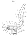
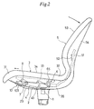
- the chair with a backrest comprises a support base 2 mounted on a leg 1, a seat 3 having a front end 31 supported on the support base 2 so as to be movable forwardly and rearwardly, a balancing member 4 positioned below the seat 3 so as to extend lengthwise thereof and having a fulcrum 43 supported on the above-mentioned support base 2 between a rear and a front point of action 41 and 42, a backrest 5 provided on the rear end 44 of the balancing member 4, seat receiving means 6 for connecting the rear end 32 of the above-mentioned seat 3 to the above-mentioned rear point of action 41 of the above-mentioned balancing member 4 so as to be movable forwardly and rearwardly, and motion translating means 7 for translating an upward movement of the above-mentioned front point of action 42 of the above-mentioned balancing member 4 to a forward movement of the above-mentioned front point of action 42 of the above-
- the support base 2 is a channel member comprising a bottom plate 21 fixed to the upper end of the above-mentioned leg 1 and a pair of side plates 22 standing integrally on the opposite lateral edges of the bottom plate 21.
- the front end 31 of the above-mentioned seat 3 is supported on the side plates 22 close to the front ends thereof by a pair of front link members 8.
- a seat receiving cover 23 is provided on the bottom of the support base 2.
- the seat 3 is composed of an inner shell not shown but mounted on a receiving frame 33, a,cushion not shown but disposed on the inner shell, and a surface finishing material 34 covering the outer surface of the cushion.
- the under surface of the above-mentioned inner shell is covered with an outer shell 35.
- the central portion of the outer shell 35 has an opening to prevent interference with the above-mentioned seat receiving cover 23.
- the above-mentioned receiving frame 33 is provided with a top plate 36 for supporting the above-mentioned inner shell, and a pair of side plates 37 depending integrally from the opposite lateral edges of the top plate 36.
- the upper pivot ends 81 of the above-mentioned front link members 8 are pivoted by a shaft 82 to the side plates 37 close to their front ends, and the lower pivot ends 83 of the front link members 8 are pivoted by a shaft 84 on the side plate 22 of the above-mentioned support base 2.
- the upper pivot ends 81 of the above-mentioned front link members 8 are so arranged as to be positioned rearwardly of the lower pivot ends 83 thereof.
- the balancing member 4 comprises a pair of parallel plates 45 extending lengthwise and a connecting plate 46 integrally connecting the rear end portions of the parallel plates 45.
- the fulcrum 43 provided at the middle point of the above-mentioned parallel plates 45 is pivotally supported by a shaft 47 on bosses 24 provided on the side plates 22 of the above-mentioned support base 2.
- the backrest 5 is connected to the rear end 44 of the balancing member 4.
- the backrest 5 comprises a frame 51 secured to the rear end of the above-mentioned balancing member 4, an inner shell not shown but secured to the frame 51 by a channel member 52, a cushion not shown but attached to the front surface of the inner shell and a surface finishing material 53 covering the outer surface of the cushion.
- An outer shell 54 covers the above-mentioned inner shell, the above-mentioned frame 51 and the channel member 52 at the rear surfaces thereof.
- the inner shell, the cushion, the surface finishing material 53 and the outer shell 54 of the backrest 5 of this embodiment are made integral with the inner shell, the cushion, the surface finishing material 34 and the outer shell 35 of the above-mentioned seat 3, respectively. However, they may be made separate from each other.
- the seat receiving means 6 is so constructed as to utilize the downwardly directed force acting on the above-mentioned seat 3 to produce a force pulling the seat 3 rearwardly.
- the above-mentioned seat receiving means 6 is provided with a pair of rear link members 65 each having an upper pivot end 61 pivoted by a shaft 62 to the above-mentioned receiving frame 33 and a lower pivot end 63 pivoted by a shaft 64 to the above-mentioned balancing member 4.
- the upper pivot ends 61 of the above-mentioned link members 65 are positioned rearwardly of the lower pivot ends 63 thereof.
- the motion translating means 7 comprises a slot 71 formed in the above-mentioned balancing member 4 close to each front point of action 42 thereof so as to extend lengthwise, an arm 72 integral with and projecting from each front link member 8, and a connecting pin 73 projecting from each arm 72 so as to slidably engage the slot 71.
- the line extending from the axis of the above-mentioned lower pivot end 83 of each front link member 8 to the axis of the upper pivot end 81 thereof is so arranged as to cross the line extending from the axis of the lower pivot end 83 to the axis of the above-mentioned connecting pin 73 at approximately right angles therewith.
- the resiliently urging means 9 comprises a main spring 91 and a pair of subsidiary springs 92.
- the main spring 91 is a tension coil spring extending between the above-mentioned shaft 82 supported by the receiving frame 33 of the above-mentioned seat 3 and a cross bar 93 supported by the rear portion of the above-mentioned support base 2.
- Each subsidiary spring 92 comprises a helical torsion spring wound around the above-mentioned shaft 84 supported on the above-mentioned support base 2.
- each subsidiary spring 92 is engaged by the above-mentioned support base 2 through a spring-force regulating mechanism 10 while the rear end 95 thereof is resiliently engaged by the above-mentioned shaft 82.
- the spring-force regulating mechanism 10 comprises a flanged bearing sleeve 101 fitted in a hole 25 formed in the front end portion of the bottom plate 21 of the above-mentioned support base 2, a control grip 103 having a stem 102 rotatably inserted through the bearing sleeve 101, a feed screw 104 integral with the stem 102 of the control grip 103, and a retainer 105 fitted to the screw 104.
- the retainer 105 for example, can be a shaft-like member crossing the above-mentioned screw 104 at right angles therewith, and provided near the opposite ends thereof with a pair of annular recesses 106 which the front ends 94 of the subsidiary springs 92 engage.
- a retainer ring 107 is provided about the stem 102 of the above-mentioned control grip 103 so as to be supported on the flange of the above-mentioned bearing sleeve 101 via a thrust bearing 108.
- the backrest 5 stands upright, and the seat 3 is kept at the most retreated position thereof.
- This reference position is set to the most suitable one for office work.
- the balancing member 4 together with the backrest 5 is pivoted rearwardly about the fulcrum 43.
- the front point of action 42 of the balancing member 4 is upwardly moved and the upward movement is transmitted to the above-mentioned seat 3, which moves forwardly with the rear end 32 thereof descending.
- each front link member 8 connected to the front point of action 42 by the connecting pin 73 of the arm 72 is forwardly pivoted about the lower pivot end 83 so that the upper pivot end 81 shifts the seat 3 forwardly.
- each rear link member 65 is also pivoted forwardly about the lower pivot end 63, which is supported on the rear point of action 41 of the above-mentioned balancing member 4.
- each rear link member 65 as a whole caused by the pivotal movement of the above-mentioned balancing member 4 is greater than that of upward movement of the upper pivot end 61 of each rear link member 65 caused by the pivotal movement of the rear link member 65, the above-mentioned seat 3 is caused to advance while descending at the rear end 32 thereof.
- the chair can be shifted to a rest position (as shown in dot-and-dash lines in Figs. 2 and 3 and Fig. 9) without giving the user a feeling of slipping forwardly.
- the above-mentioned backrest 5 is pivoted rearwardly about the fulcrum 43 of the balancing member 4 disposed below the seat 3, so that the whole backrest 5 is shifted rearwardly while being inclined rearwardly. Therefore, the motion of the user's back acting on the backrest 5 properly coincides with the movement of the chair back 5, so that the user does not feel uncomfortable.
- the seat 3 advances, so that it is possible to prevent occurrence of a troublesome condition that the center of gravity of the user is shifted rearwardly thereby to cause the chair to fall down rearwardly.
- the chair is provided with resiliently urging means 9 for resiliently urging the above-mentioned seat 3 rearwardly.
- resiliently urging means 9 for resiliently urging the above-mentioned seat 3 rearwardly.
- a backward pulling force corresponding to the weight of the user seated in the chair acts on the seat 3.
- the rear link members 65 constituting the seat receiving means 6 are inclined rearwardly. Under the condition, if a downward force corresponding to the weight of the user acts on the upper pivot ends 61 of the rear link members 65 through the seat 3, the rear link members 65 are shifted rearwardly. As a result, a rearward pulling force is applied to the receiving frame 33 of the seat 3 connected to the upper pivot ends 61 of the rear link members 65.
- This pulling force acts as a downward force on the front point of action 42 of the above-mentioned balancing member 4 through the motion translating means 7.
- a force acting on the front link members 8 to cause them to pivot rearwardly is applied to the front link members 8 having their upper pivot ends 81 connected to the receiving frame 33.
- the arm 72 provided on each front link member 8 is pivoted downwardly, and the connecting pin 73 projecting from each arm 72 pushes the front point of action 42 of the above-mentioned balancing member 4 downwardly.
- An additional downward force caused by the weight of the user acts on the upper pivot ends 81 of the front link members 8 through the seat 3.
- This downward force also acts as a force to pivot the front link members 8 rearwardly, and functions as a force to push the front point of action 42 of the above-mentioned balancing member 4 downwardly through the above-mentioned connecting pins 73.
- a downward force increasing or decreasing depending upon the weight of the user (which force will be referred to as "the weight-depending front force" for abbreviation hereinafter) is applied to the front point of action 42 of the above-mentioned balancing member 4.
- a downward force increasing or decreasing depending upon the weight of the user (which force will be referred to as "the weight-depending rear force” for abbreviation hereinafter) is applied to the rear point of action 41 of the balancing member 4 through the rear link members 65.
- the arrangement is such that the weight-depending rear force acting on the rear point of action 41 cannot offset the weight-depending front force acting on the front point of action 42.
- the position of the fulcrum 43 and the dimensions of the component members are preset so that the previously mentioned downward force increasing or decreasing depending upon the weight of the user remains on the front point of action 42.
- the above-mentioned balancing member 4 and backrest 5 are pivoted forwardly by a force corresponding to the weight. Therefore, a user of a heavy weight must exert a large force to incline the backrest rearwardly, while a user of a light weight needs only a smaller force.
- the backrest 5. is inclined rearwardly by a user directly pushing it with his back. Usually, a person of a heavy weight has a larger force than a person of a light weight to push the backrest with his back. Therefore, it is preferable that the force for operating the backrest should vary in the above-mentioned manner. If chairs for use in meeting rooms or with office automation equipment, that is, chairs to be used commonly by persons of different physiques have such functions as mentioned above, the initial repellent strength of the backrest 5 need not be adjusted to different users, so that the chair can be used conveniently.
- the above-mentioned operation is conducted at the initial stage where the backrest 5 begins to be inclined rearwardly from the above-mentioned reference position.
- the above-mentioned weight-depending front force acting on the front point of action 42 of the balancing member 4 gradually decreases.
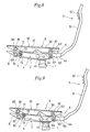
- the above-mentioned weight-depending rear force acting on the rear point of action 41 of the balancing member 4 does not greatly change in spite of the change in inclination of the front link members 8. Therefore, the priority of the weight-depending front force disappears well before the link members 8 and 65 stand upright as shown in Fig. 8, so that the repellent force of the backrest 5 no longer increases or decreases depending upon the weight of the user.
- the above-mentioned seat 3 is resiliently urged rearwardly by the main spring 91 and the subsidiary springs 92. Therefore, this resilient urging force functions as a dowmward force (which will be referred to as "the spring-depending force" for abbreviation hereinafter) on the front point of action 42 of the above-mentioned balancing member 4 through the the front link members 8.
- the spring-depending force increases as the seat 3 advances to increase the amount of resilient deformation of the springs 91 and 92.
- the spring-depeding force only urges the backrest 5 forwardly.
- the spring-depending force is produced by the pulling force of the main spring 91 and the pressing force of the subsidiary springs 92. Therefore, by adjusting the spring force of the above-mentioned subsidiary springs 92 it is possible to change the spring-depending force thereby to change the magnitude of the force to urge the backrest 5 forwardly. If a single spring corresponding to the above-mentioned main spring 91 was provided to urge the seat 3 rearwardly, a complicated mechanism would be required to adjust the spring force from outside.
- the chair of the invention is so arranged that the seat 3 is urged rearwardly by the main spring 91 and the subsidiary springs 92, and the subsidiary springs 92 are provided at the forward end of the support base 2, it is possible to adjust the spring force of the springs from outside by using the above-mentioned simple spring-adjusting mechanism 10. With this arrangement, it is also possible to arrange so that at the initial stage of inclination of the backrest 5 the subsidiary springs 92 do not work, and that when the weight-depending force has stopped urging the backrest 5 forwardly, the subsidiary springs 92 become active.
- the main spring is of such a type that the spring force increases linearly as it expands.
- the spring may also be of such a type that as the spring expands, the spring force increases curvilinearly with its rate of change increasng.
- the spring having such a characteristic there is available a coil spring which has a high coil density in the opposite ends and a low coil density in the middle thereof.
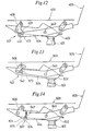
- the balancing member 204 shown in Fig. 10 has a pair of slots 248 in its fulcrum 243.
- the balancing member 204 is swingably supported by a shaft 247 fixed to the support base 202 and engaging the slot 248.
- a pivoting mechanism can be provided in not only the connection between each rear link member 265 and the balancing member 204 but also the connection between each front link member 298 and the balancing member 204.
- 201 is a leg
- 203 is a seat
- 205 is a backrest.
- the balancing member 304 shown in Fig 11 has its fulcrum 343 pivoted to the lower end of a pair of central link members 348.
- the upper end of each central link member 348 is pivoted to the support base 302.
- the pivoting mechanism always makes it possible to have the outer surface of the pivot shaft in contact with or close to the inner surface of the hole for receiving the shaft, it can effectively prevent foreign bodies from entering between the surfaces thereby to avoid or suppress increase of the sliding resistance therebetween and production of screeching sounds for a long time. Since chairs are usually used for a long period of time without particular maintenance work, it is advantageous that all connecting portions of movable parts include a pivoting mechanism.
- 301 is a leg
- 303 is a seat
- 305 is a backrest.
- a pin 473 is fixed to the front point of action 442 of the balancing member 404, and the pin 473 is in sliding contact with the lower edge of the arm 472 of each front link member 408.
- 401 is a leg
- 402 is a support base
- 403 is a seat
- 405 is a backrest
- 443 is a fulcrum.
- a pin 573 is fixed to the front point of action 542 of the balancing member 504, and the pin 573 is in sliding contact with the rear edge of each front link member 508 inclined rearwardly.
- 501 is a leg
- 502 is a seat
- 505 is a backrest
- 543 is a fulcrum.
- a pair of projections 748 are provided on the rear point of action 741 of the balancing member 704, and a pin 749 projecting from each projection 748 slidably engages each slot 738 formed in the receiving frame 733 of the above-mentioned seat 703.
- 701 is a leg
- 702 is a support base
- 705 is a backrest
- 743 is a fulcrum.
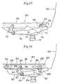
- a pivotable frame 861 is arranged below the receiving frame 833 of the seat 803 with the front end thereof pivotally supported on the support base 802, and the rear end of the pivotable frame 861 is supported on the rear point of action 841 of the balancing member 804 through each link member 865, with a pin 862 standing near the rear end of the frame 861 and slidably engaging each slot 838 formed in the abaove-mentioned receiving frame 833.
- a pair of slots 839 is also provided near the front end of the above-mentioned receiving frame 833, and a pin 863 projecting from the front end of the above-mentioned support base 802 slidably engages each slot 839 thereby to support the front end of the seat 803 on the above-mentioned support base 802.
- a vertically extending, rearwardly inclined slot 871 is provided in each side plate of the above-mentioned receiving frame 833, and a pin 881 projecting from the upper end of each front link member 808 slidably engages, the slot 871.
- a connecting pin 873 projects from the arm 872 of each front link member 808, and slidably engages each slot 871 formed at the front point of action 842 in the balancing member 804.
- pivotable frame 861 has its rear end connected to the rear point of action 841 of the balancing member 804, the rear pin 862 descends with forward movement of the receiving frame 833. Therefore, when the chair is observed as a whole, as the backrest 805 is inclined rearwardly and the seat 803 advances, the rear end of the seat 803 descends properly.
- the slots 838 and 839 may extend horizontally or slightly aslant forwardly.
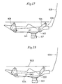
- the seat receiving means 906 shown in Fig. 17 is provided with a pair of rear link members 965 of a different length from the front link members 908.
- 901 designates a leg
- 902 designates a support base
- 905 designates a backrest
- 943 designates a fulcrum.
- Fig. 18 shows another embodiment in which the fulcrum 1043 of the balancing member 1004 is set at a relatively forward position.
- 1001 is a leg
- 1002 is a support base
- 1003 is a seat
- 1005 is a backrest.
- Figs. 19 and 20 show an embodiment in which locking means 1108 is provided between the support base 1102 and the balancing member 1104.
- the locking means 1108 is constructed by alternately piling up a plurality of friction plates 1182 each having a vertically extending slot 1181 and a leaf spring 1184 having a vertically extending slot 1183 with a spacer 1185 interposed therebetween, and fastening the upper ends of these friction plates 1182, the upper end of the above-mentioned leaf spring 1184 and the above-mentioned spacers 1185 to the boss 1121 of the support base 1102 by means of a fastening shaft 1186.
- a pin 1141 provided on the balancing member 1104 slidably engages the above-mentioned slots 1181 and 1183, and a plurality of pad members 1187 mounted on the pin 1141 are interposed between the balancing member 1104 and the above-mentioned friction plates 1182, between adjacent two friction plates 1182, and between the friction plates 1182 and the leaf spring 1184.
- a wire 1183 is connected to the lower end of the leaf spring 1184 for pulling it outwardly. By handling an operating lever not shown but provided below the seat 1103 the wire 1183 can be pulled. With this arrangements when no pulling force is exerted on the wire 1188, the resilient force of the leaf spring 1184, presses the pad members 1187, the friction plates 1182 and the leaf spring 1184 against each other.
- the movement of the balancing member 1104 is braked by the frictional force produced at the pressed areas between the members, so that the seat 1103 and the backrest 1105 are locked.
- the above-mentioned leaf spring 1184 is outwardly curved thereby to release the pressed condition of the pad members 1187 and the friction plates 1182.
- the balancing member 1104 can be pivoted, and the above-mentioned locked condition of the seat 1103 and the backrest 1105 is released.
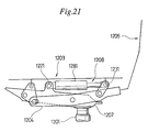
- Fig. 21 shows another embodiment of the locking means.
- This locking means 1208 comprises a gas spring 1281 of a construction similar to the gas spring used for adjusting the length of the legs of a chair and interposed between the support base 1202 and the seat 1203.
- the gas spring 1281 which extends by the repelling force of a gas enclosed therein is provided between a cross member 1221 mounted on the above-mentioned support base 1202 and a shaft 1231 mounted on the rear end of the seat 1203.
- the gas spring 1281 has built therein a valve mechanism for stopping flow of the interior fluid and locking the extension of the spring, it being possible to open and close the valve mechanism from outside.
- the valve mechanism can be controlled by a control lever not shown but provided below the seat 1203.
- 1201 is a leg
- 1204 is a balancing member
- 1205 is a backrest.
- the valve mechanism of the gas spring 1281 is kept at a closed position thereby to prevent free extension or contraction of the gas spring 1281, the seat 1203 cannot freely move forwardly or rearwardly, so that inclination of the backrest 1205 is restricted.
- the gas spring 1281 performs its spring function to resiliently urge the seat 1203 rearwardly. Then, when the user pushes the backrest 1205 rearwardly against the resilient force, the seat can be shifted to its rest position.
- the gas spring 1281 of this embodiment also functions as resiliently urging means.
- the chair with a backrest constructed in accordance with the invention is suitable for use as a chair in a meeting room, for office work, or a chair an operator of an OA instrument uses.
- the invention can also be applied to a chair without a leg.
Landscapes
- Health & Medical Sciences (AREA)
- Dentistry (AREA)
- General Health & Medical Sciences (AREA)
- Chairs Characterized By Structure (AREA)
- Chairs For Special Purposes, Such As Reclining Chairs (AREA)
Abstract
Applications Claiming Priority (1)
| Application Number | Priority Date | Filing Date | Title |
|---|---|---|---|
| PCT/JP1987/000818 WO1989003649A1 (fr) | 1987-10-24 | 1987-10-24 | Chaise basculante |
Publications (3)
| Publication Number | Publication Date |
|---|---|
| EP0339089A1 true EP0339089A1 (fr) | 1989-11-02 |
| EP0339089A4 EP0339089A4 (fr) | 1990-02-26 |
| EP0339089B1 EP0339089B1 (fr) | 1992-08-19 |
Family
ID=13902894
Family Applications (1)
| Application Number | Title | Priority Date | Filing Date |
|---|---|---|---|
| EP87906940A Expired - Lifetime EP0339089B1 (fr) | 1987-10-24 | 1987-10-24 | Chaise basculante |
Country Status (5)
| Country | Link |
|---|---|
| US (1) | US4966411A (fr) |
| EP (1) | EP0339089B1 (fr) |
| DE (1) | DE3781282T2 (fr) |
| NL (1) | NL193438C (fr) |
| WO (1) | WO1989003649A1 (fr) |
Cited By (14)
| Publication number | Priority date | Publication date | Assignee | Title |
|---|---|---|---|---|
| EP0418731A1 (fr) * | 1989-09-16 | 1991-03-27 | Rolf Völkle | Chaise |
| FR2725352A1 (fr) * | 1994-10-11 | 1996-04-12 | Kusch Co Sitzmoebel | Meuble utilise pour s'asseoir, notamment chaise ou fauteuil de bureau, comportant un mecanisme de basculement du siege et du dossier |
| EP0960586A3 (fr) * | 1998-05-27 | 2001-03-28 | Röder, Peter | Chaise, notamment chaise de bureau |
| EP1911371A1 (fr) * | 2006-10-10 | 2008-04-16 | Interstuhl Büromöbel GmbH & Co. KG | Meuble d'assise, en particulier chaise de bureau |
| DE102006056928B3 (de) * | 2006-12-04 | 2008-06-05 | Sato Office Gmbh | Sitz mit einer Sitzplatte und einer Rückenlehne |
| WO2009153811A1 (fr) * | 2008-06-17 | 2009-12-23 | Co.Fe.Mo. S.P.A. | Dispositif de réglage pour chaises |
| EP3103369A1 (fr) * | 2015-06-11 | 2016-12-14 | Davis Furniture Industries, Inc. | Chaises |
| CN106263726A (zh) * | 2015-05-22 | 2017-01-04 | 陈竑燊 | 办公椅椅背与坐垫之间的连动倾仰装置 |
| US10575648B2 (en) | 2015-04-13 | 2020-03-03 | Steelcase Inc. | Seating arrangement |
| US11096497B2 (en) | 2015-04-13 | 2021-08-24 | Steelcase Inc. | Seating arrangement |
| US11109683B2 (en) | 2019-02-21 | 2021-09-07 | Steelcase Inc. | Body support assembly and method for the use and assembly thereof |
| US11259637B2 (en) | 2015-04-13 | 2022-03-01 | Steelcase Inc. | Seating arrangement |
| US11357329B2 (en) | 2019-12-13 | 2022-06-14 | Steelcase Inc. | Body support assembly and methods for the use and assembly thereof |
| US12582234B2 (en) | 2017-06-09 | 2026-03-24 | Steelcase Inc. | Seating arrangement |
Families Citing this family (83)
| Publication number | Priority date | Publication date | Assignee | Title |
|---|---|---|---|---|
| US5207479A (en) * | 1990-06-06 | 1993-05-04 | Kimball International, Inc. | Chair control mechanism |
| US5378039A (en) * | 1990-08-20 | 1995-01-03 | Ring Mekanikk As | Torsion spring and adjustable mounting for chair |
| US5318345A (en) * | 1991-06-07 | 1994-06-07 | Hon Industries, Inc. | Tilt back chair and control |
| DE9112861U1 (de) * | 1991-10-16 | 1992-01-02 | SIFA Sitzfabrik GmbH, 8458 Sulzbach-Rosenberg | Vorrichtung zur Gewichtseinstellung für die Einstellung von Sitzflächen und Rückenlehnen bei Stühlen, insbesondere Bürodrehstühlen |
| BR9307983B1 (pt) | 1992-06-15 | 2010-07-27 | estrutura de assento e método de fabricação da mesma. | |
| DE4312113C1 (de) * | 1993-04-14 | 1994-10-27 | Mauser Waldeck Ag | Sitzmöbel |
| US5388889A (en) * | 1993-09-23 | 1995-02-14 | Westinghouse Electric Corporation | Torque control mechanism for chairs |
| JP2980185B2 (ja) * | 1994-04-12 | 1999-11-22 | アイコ株式会社 | 椅子の座の傾動方法および傾動自在の座を備えた椅子 |
| ES2110875B1 (es) * | 1994-04-21 | 1998-11-16 | Jevit Manufact Metalicas Sa | Sillon ergonomico autoequilibrado. |
| GB9500022D0 (en) * | 1995-01-04 | 1995-03-01 | Unwalla Jamshed | Integrated seat and back and mechanism for chairs |
| US5573303A (en) * | 1995-05-16 | 1996-11-12 | Doerner Products Ltd. | Chair seat tilting mechanism |
| US5765914A (en) * | 1995-06-07 | 1998-06-16 | Herman Miller, Inc. | Chair with a tilt control mechanism |
| WO1998016138A1 (fr) * | 1996-10-11 | 1998-04-23 | Giroflex Entwicklungs Ag | Siege, notamment siege de bureau |
| JPH10272031A (ja) * | 1997-03-31 | 1998-10-13 | Aiko Kk | 椅子の座の傾動方法および傾動自在の座を備えた椅子 |
| JP3136280B2 (ja) * | 1997-04-28 | 2001-02-19 | 株式会社いのうえアソシエーツ | 椅 子 |
| DE19740045B4 (de) * | 1997-09-12 | 2006-07-06 | C. Rob. Hammerstein Gmbh & Co. Kg | Fahrzeugsitz mit Rückenlehne und Sitzschale |
| US5871258A (en) * | 1997-10-24 | 1999-02-16 | Steelcase Inc. | Chair with novel seat construction |
| US6250715B1 (en) | 1998-01-21 | 2001-06-26 | Herman Miller, Inc. | Chair |
| IT245520Y1 (it) * | 1998-07-16 | 2002-03-22 | Beniamino Miotto | Dispositivo meccanico particolarmente per la movimentazione sincronadi sedile e schienale di una sedia. |
| SE512936C2 (sv) | 1998-09-10 | 2000-06-05 | Bertil Jonsson | Stol |
| US6705677B2 (en) * | 2000-02-18 | 2004-03-16 | Sugatsun Kogyo Co., Ltd | Chair with seatback and rotating damper device |
| WO2001070073A1 (fr) * | 2000-03-17 | 2001-09-27 | Herman Miller, Inc. | Ensemble basculeur destine a une chaise |
| NZ515698A (en) * | 2000-05-22 | 2003-03-28 | Miller Herman Inc | Office chair characterised by pivotal and slidable members for restricting forward and rearward movements |
| US6739665B1 (en) * | 2000-11-30 | 2004-05-25 | Krueger International, Inc. | Seat mounting system for a motion chair |
| US6842959B2 (en) * | 2001-01-25 | 2005-01-18 | Dahti, Inc. | Load bearing fabric attachment and associated method |
| CA2525902A1 (fr) * | 2001-01-25 | 2002-07-25 | Jsj Seating Company Texas, L.P. | Fauteuil de bureau |
| US6585320B2 (en) | 2001-06-15 | 2003-07-01 | Virco Mgmt. Corporation | Tilt control mechanism for a tilt back chair |
| US6644741B2 (en) | 2001-09-20 | 2003-11-11 | Haworth, Inc. | Chair |
| US6679553B2 (en) * | 2002-03-01 | 2004-01-20 | Steelcase Development Corporation | Energy system assembly for seating unit |
| US7625046B2 (en) | 2002-03-29 | 2009-12-01 | Garrex Llc | Task chair |
| US7396082B2 (en) | 2002-03-29 | 2008-07-08 | Garrex Llc | Task chair |
| US7040703B2 (en) | 2002-03-29 | 2006-05-09 | Garrex Llc | Health chair a dynamically balanced task chair |
| US6869142B2 (en) * | 2002-09-12 | 2005-03-22 | Steelcase Development Corporation | Seating unit having motion control |
| US7165811B2 (en) * | 2002-09-12 | 2007-01-23 | Steelcase Development Corporation | Control mechanism for seating unit |
| US7048335B2 (en) * | 2003-06-05 | 2006-05-23 | Steelcase Development Corporation | Seating unit with crossbar seat support |
| US6945602B2 (en) * | 2003-12-18 | 2005-09-20 | Haworth, Inc. | Tilt control mechanism for chair |
| WO2005112704A2 (fr) * | 2004-05-13 | 2005-12-01 | Humanscale Corporation | Composant de chaise en maillage |
| DE102004050853A1 (de) * | 2004-10-18 | 2006-04-20 | Interstuhl Büromöbel GmbH & Co. KG | Stuhl |
| DE102005009419A1 (de) * | 2005-03-02 | 2006-09-07 | Recaro Aircraft Seating Gmbh & Co. Kg | Sitz |
| USD623449S1 (en) | 2005-05-13 | 2010-09-14 | Humanscale Corporation | Mesh backrest for a chair |
| US8061775B2 (en) * | 2005-06-20 | 2011-11-22 | Humanscale Corporation | Seating apparatus with reclining movement |
| US7293832B2 (en) * | 2005-08-19 | 2007-11-13 | Chien-Kai Huang | Chair adjustable device |
| EP2001338B1 (fr) * | 2006-03-24 | 2016-10-26 | Herman Miller Inc. | Structure de support du corps |
| US7717515B2 (en) * | 2006-04-24 | 2010-05-18 | Humanscale Corporation | Chair having an automatically adjusting resistance to tilting |
| USD661135S1 (en) | 2006-06-20 | 2012-06-05 | Humanscale Corporation | Pair of armrests for a chair or the like |
| CN102772053A (zh) | 2007-01-29 | 2012-11-14 | 赫尔曼米勒有限公司 | 座位结构及其使用方法 |
| JP5179798B2 (ja) * | 2007-05-22 | 2013-04-10 | 株式会社デルタツーリング | 座席構造 |
| ITTO20070398A1 (it) * | 2007-06-06 | 2008-12-07 | Malenotti S R L | "sedia con schienale oscillante" |
| US8015981B2 (en) * | 2007-08-19 | 2011-09-13 | Anastasia Soare | Stencils and gauging device for aesthetically pleasing eyebrow shaping |
| CN201123561Y (zh) * | 2007-09-06 | 2008-10-01 | 陈登慧 | 椅子结构 |
| JP5490004B2 (ja) * | 2007-09-20 | 2014-05-14 | ハーマン、ミラー、インコーポレイテッド | 身体支持構造 |
| DE102008011309B3 (de) * | 2008-02-27 | 2009-06-04 | Thonet Gmbh | Bürostuhl |
| TW200950726A (en) * | 2008-06-06 | 2009-12-16 | Fon Chin Ind Co Ltd | Front-and-back reciprocating, reclining, lifting and lowering apparatus for a chair back |
| US8002351B2 (en) * | 2009-01-26 | 2011-08-23 | Knoll, Inc. | Support member |
| DE102009009287A1 (de) * | 2009-02-17 | 2010-09-09 | Uhlenbrock, Christel | Sitzmöbel, insbesondere Bürodrehstuhl |
| CH701715A2 (de) * | 2009-08-26 | 2011-02-28 | Vitra Patente Ag | Mechanik für einen Stuhl. |
| US8613482B2 (en) * | 2010-02-08 | 2013-12-24 | Hangzhou Zhongtai Industrial Co., Ltd. | Chair chassis |
| KR101533650B1 (ko) * | 2010-04-15 | 2015-07-03 | 주식회사 시디즈 | 의자의 등받이에 작용하는 복원력을 조정하기 위한 조정 메커니즘 및 상기 조정 메커니즘을 구비한 사무용 의자 |
| GB201014953D0 (en) * | 2010-09-08 | 2010-10-20 | Birkbeck Hilary R | Slide chair action |
| GB201015414D0 (en) | 2010-09-15 | 2010-10-27 | Birkbeck Hilary R | Link chair action |
| EP2739184B1 (fr) * | 2011-08-03 | 2015-07-08 | Haworth, Inc. | Mécanisme de réglage permettant de déterminer une force de rappel qui agit sur un dossier d'une chaise, et chaise de bureau qui comporte un mécanisme de réglage de ce type |
| JP6009891B2 (ja) * | 2011-11-04 | 2016-10-19 | 株式会社岡村製作所 | 椅子 |
| US9504326B1 (en) | 2012-04-10 | 2016-11-29 | Humanscale Corporation | Reclining chair |
| US9706845B2 (en) | 2012-09-20 | 2017-07-18 | Steelcase Inc. | Chair assembly |
| US11304528B2 (en) | 2012-09-20 | 2022-04-19 | Steelcase Inc. | Chair assembly with upholstery covering |
| USD697726S1 (en) | 2012-09-20 | 2014-01-21 | Steelcase Inc. | Chair |
| TWM483731U (zh) * | 2013-12-31 | 2014-08-11 | Yong-Hua Chen | 辦公椅結構 |
| EP2896325B1 (fr) * | 2014-01-20 | 2018-02-28 | L&P Property Management Company | Mécanisme d'inclinaison pour meuble pour s'asseoir et meuble de type siège comprenant celui-ci |
| WO2015161281A1 (fr) | 2014-04-17 | 2015-10-22 | Hni Technologies Inc. | Chaise et ensembles, systèmes et procédés de commande de chaise |
| US9167902B1 (en) * | 2014-07-01 | 2015-10-27 | Yung-hua Chen | One-piece office chair in three dimensions |
| NO339052B1 (no) * | 2014-10-27 | 2016-11-07 | Sykkylven Staal As | Anordning ved sittemøbel |
| GB2536290B (en) * | 2015-03-13 | 2017-06-07 | Deep Thought Ltd | Self-weigh mechanism for office chair |
| DE102015111946A1 (de) * | 2015-07-22 | 2017-01-26 | Bock 1 Gmbh & Co. Kg | Mechanik für einen Bürostuhl |
| DE102016104638A1 (de) * | 2016-03-14 | 2017-09-14 | Burkhard Schmitz | Stuhl |
| WO2018116426A1 (fr) * | 2016-12-21 | 2018-06-28 | コクヨ株式会社 | Chaise |
| US11589678B2 (en) | 2019-01-17 | 2023-02-28 | Hni Technologies Inc. | Chairs including flexible frames |
| TWM589493U (zh) * | 2019-09-05 | 2020-01-21 | 林長貞 | 座椅組成結構 |
| US11197548B2 (en) * | 2019-12-16 | 2021-12-14 | Allseating Corporation | Reclining control system for a chair |
| US11690455B2 (en) * | 2020-09-18 | 2023-07-04 | Dinkar Chellaram | Synchronous-tilt reclining chair |
| WO2023086245A1 (fr) * | 2021-11-09 | 2023-05-19 | Steelcase Inc. | Système de commande d'inclinaison pour chaise |
| US20230165370A1 (en) * | 2021-11-26 | 2023-06-01 | Benlong Sun | Adjustable rotary rocking chair |
| IT202200009566A1 (it) * | 2022-05-10 | 2023-11-10 | Brado S P A | Dispositivo di regolazione per una sedia con meccanismo oscillante |
| IT202200009572A1 (it) * | 2022-05-10 | 2023-11-10 | Brado S P A | Dispositivo di regolazione per una sedia con meccanismo oscillante. |
Family Cites Families (8)
| Publication number | Priority date | Publication date | Assignee | Title |
|---|---|---|---|---|
| NL85451C (fr) * | 1955-06-02 | 1957-06-15 | ||
| CH529537A (de) * | 1970-09-28 | 1972-10-31 | Stella Werke Ag | Arbeitsstuhl |
| JPS50152905U (fr) * | 1974-06-05 | 1975-12-19 | ||
| CH645795A5 (en) * | 1979-07-23 | 1984-10-31 | Drabert Soehne | Chair, in particular visual display unit chair |
| CH666171A5 (de) * | 1984-10-03 | 1988-07-15 | Giroflex Entwicklungs Ag | Stuhl mit rueckwaerts neigbarem sitz- und rueckenlehnentraeger. |
| DE3537203A1 (de) * | 1984-10-24 | 1986-04-24 | Klöber GmbH & Co, 7770 Überlingen | Arbeitsstuhl mit neigungsmechanik von sitzschale und rueckenlehne |
| DE8614186U1 (de) * | 1986-05-26 | 1986-07-17 | Drabert Söhne GmbH & Co, 4950 Minden | Stuhl |
| DE3617624A1 (de) * | 1986-05-26 | 1987-12-03 | Drabert Soehne | Stuhl |
-
1987
- 1987-10-24 WO PCT/JP1987/000818 patent/WO1989003649A1/fr not_active Ceased
- 1987-10-24 EP EP87906940A patent/EP0339089B1/fr not_active Expired - Lifetime
- 1987-10-24 DE DE8787906940T patent/DE3781282T2/de not_active Expired - Lifetime
- 1987-10-24 US US07/368,348 patent/US4966411A/en not_active Expired - Lifetime
-
1988
- 1988-10-24 NL NL8802614A patent/NL193438C/nl not_active IP Right Cessation
Cited By (24)
| Publication number | Priority date | Publication date | Assignee | Title |
|---|---|---|---|---|
| EP0418731A1 (fr) * | 1989-09-16 | 1991-03-27 | Rolf Völkle | Chaise |
| FR2725352A1 (fr) * | 1994-10-11 | 1996-04-12 | Kusch Co Sitzmoebel | Meuble utilise pour s'asseoir, notamment chaise ou fauteuil de bureau, comportant un mecanisme de basculement du siege et du dossier |
| EP0960586A3 (fr) * | 1998-05-27 | 2001-03-28 | Röder, Peter | Chaise, notamment chaise de bureau |
| US7600814B2 (en) | 2006-10-10 | 2009-10-13 | Interstuhl Bueromoebel Gmbh & Co. Kg | Seating furniture item, in particular office chair |
| EP1911371A1 (fr) * | 2006-10-10 | 2008-04-16 | Interstuhl Büromöbel GmbH & Co. KG | Meuble d'assise, en particulier chaise de bureau |
| DE102006056928B3 (de) * | 2006-12-04 | 2008-06-05 | Sato Office Gmbh | Sitz mit einer Sitzplatte und einer Rückenlehne |
| CN101573060B (zh) * | 2006-12-04 | 2011-09-28 | Sato办公用品有限公司 | 具有座板和椅背的座椅 |
| US8215710B2 (en) | 2006-12-04 | 2012-07-10 | Sato Office Gmbh | Seat having a seat panel and a backrest |
| WO2009153811A1 (fr) * | 2008-06-17 | 2009-12-23 | Co.Fe.Mo. S.P.A. | Dispositif de réglage pour chaises |
| US8646839B2 (en) | 2008-06-17 | 2014-02-11 | Co.Fe.Mo. Industrie S.R.L. | Adjustment device for chairs |
| US11963621B2 (en) | 2015-04-13 | 2024-04-23 | Steelcase Inc. | Seating arrangement |
| US11259637B2 (en) | 2015-04-13 | 2022-03-01 | Steelcase Inc. | Seating arrangement |
| US10575648B2 (en) | 2015-04-13 | 2020-03-03 | Steelcase Inc. | Seating arrangement |
| US11096497B2 (en) | 2015-04-13 | 2021-08-24 | Steelcase Inc. | Seating arrangement |
| US11324325B2 (en) | 2015-04-13 | 2022-05-10 | Steelcase Inc. | Seating arrangement |
| CN106263726A (zh) * | 2015-05-22 | 2017-01-04 | 陈竑燊 | 办公椅椅背与坐垫之间的连动倾仰装置 |
| US9713381B2 (en) | 2015-06-11 | 2017-07-25 | Davis Furniture Industries, Inc. | Chair |
| EP3103369A1 (fr) * | 2015-06-11 | 2016-12-14 | Davis Furniture Industries, Inc. | Chaises |
| US12582234B2 (en) | 2017-06-09 | 2026-03-24 | Steelcase Inc. | Seating arrangement |
| US11109683B2 (en) | 2019-02-21 | 2021-09-07 | Steelcase Inc. | Body support assembly and method for the use and assembly thereof |
| US11357329B2 (en) | 2019-12-13 | 2022-06-14 | Steelcase Inc. | Body support assembly and methods for the use and assembly thereof |
| US11786039B2 (en) | 2019-12-13 | 2023-10-17 | Steelcase Inc. | Body support assembly and methods for the use and assembly thereof |
| US11805913B2 (en) | 2019-12-13 | 2023-11-07 | Steelcase Inc. | Body support assembly and methods for the use and assembly thereof |
| US12161232B2 (en) | 2019-12-13 | 2024-12-10 | Steelcase Inc. | Body support assembly and methods for the use and assembly thereof |
Also Published As
| Publication number | Publication date |
|---|---|
| US4966411A (en) | 1990-10-30 |
| NL193438C (nl) | 1999-11-02 |
| WO1989003649A1 (fr) | 1989-05-05 |
| NL8802614A (nl) | 1989-05-16 |
| EP0339089B1 (fr) | 1992-08-19 |
| DE3781282D1 (de) | 1992-09-24 |
| DE3781282T2 (de) | 1992-12-17 |
| EP0339089A4 (fr) | 1990-02-26 |
| NL193438B (nl) | 1999-07-01 |
Similar Documents
| Publication | Publication Date | Title |
|---|---|---|
| EP0339089A1 (fr) | Chaise basculante | |
| US5765914A (en) | Chair with a tilt control mechanism | |
| JP2612987B2 (ja) | 可倒式椅子の配置構造 | |
| JP4958351B2 (ja) | リクライン可能な椅子 | |
| US6234573B1 (en) | Chair, in particular office chair | |
| US5385388A (en) | Split back chair | |
| EP0971613B1 (fr) | Agencement pour lits et autre mobilier pouvant s'incliner ou du type siege | |
| US5375912A (en) | Reclining chair | |
| CA2087981A1 (fr) | Chaise de travail, plus specialement une chaise de bureau | |
| KR930004458B1 (ko) | 안락 의자 | |
| US5197781A (en) | Reclining apparatus | |
| CN113142869B (zh) | 一种可前后倾仰的椅子 | |
| KR20110022040A (ko) | 기울임 가능한 등받이를 갖는 의자 | |
| JP2002119347A (ja) | 椅 子 | |
| CN221902988U (zh) | 腰靠档位调节装置及座椅 | |
| JPH01139013A (ja) | 椅子 | |
| JPH0439724Y2 (fr) | ||
| JPS60249915A (ja) | 椅子 | |
| JP2026071873A (ja) | 椅子 | |
| JP2026047272A (ja) | 椅子 | |
| JP2004248980A (ja) | 椅子 | |
| JPH0360606A (ja) | 椅子の傾動装置 | |
| JPH0795968B2 (ja) | 背もたれ付椅子 | |
| MXPA97009895A (en) | Adjustment height armrests assembly |
Legal Events
| Date | Code | Title | Description |
|---|---|---|---|
| PUAI | Public reference made under article 153(3) epc to a published international application that has entered the european phase |
Free format text: ORIGINAL CODE: 0009012 |
|
| 17P | Request for examination filed |
Effective date: 19890530 |
|
| AK | Designated contracting states |
Kind code of ref document: A1 Designated state(s): BE CH DE FR GB IT LI |
|
| A4 | Supplementary search report drawn up and despatched |
Effective date: 19900226 |
|
| 17Q | First examination report despatched |
Effective date: 19910226 |
|
| GRAA | (expected) grant |
Free format text: ORIGINAL CODE: 0009210 |
|
| AK | Designated contracting states |
Kind code of ref document: B1 Designated state(s): BE CH DE FR GB IT LI |
|
| REF | Corresponds to: |
Ref document number: 3781282 Country of ref document: DE Date of ref document: 19920924 |
|
| ITF | It: translation for a ep patent filed | ||
| ET | Fr: translation filed | ||
| PLBE | No opposition filed within time limit |
Free format text: ORIGINAL CODE: 0009261 |
|
| STAA | Information on the status of an ep patent application or granted ep patent |
Free format text: STATUS: NO OPPOSITION FILED WITHIN TIME LIMIT |
|
| 26N | No opposition filed | ||
| REG | Reference to a national code |
Ref country code: GB Ref legal event code: IF02 |
|
| PGFP | Annual fee paid to national office [announced via postgrant information from national office to epo] |
Ref country code: FR Payment date: 20031003 Year of fee payment: 17 |
|
| PGFP | Annual fee paid to national office [announced via postgrant information from national office to epo] |
Ref country code: GB Payment date: 20031022 Year of fee payment: 17 |
|
| PGFP | Annual fee paid to national office [announced via postgrant information from national office to epo] |
Ref country code: CH Payment date: 20031030 Year of fee payment: 17 |
|
| PGFP | Annual fee paid to national office [announced via postgrant information from national office to epo] |
Ref country code: DE Payment date: 20031103 Year of fee payment: 17 |
|
| PGFP | Annual fee paid to national office [announced via postgrant information from national office to epo] |
Ref country code: BE Payment date: 20031211 Year of fee payment: 17 |
|
| PG25 | Lapsed in a contracting state [announced via postgrant information from national office to epo] |
Ref country code: GB Free format text: LAPSE BECAUSE OF NON-PAYMENT OF DUE FEES Effective date: 20041024 |
|
| PG25 | Lapsed in a contracting state [announced via postgrant information from national office to epo] |
Ref country code: LI Free format text: LAPSE BECAUSE OF NON-PAYMENT OF DUE FEES Effective date: 20041031 Ref country code: CH Free format text: LAPSE BECAUSE OF NON-PAYMENT OF DUE FEES Effective date: 20041031 Ref country code: BE Free format text: LAPSE BECAUSE OF NON-PAYMENT OF DUE FEES Effective date: 20041031 |
|
| BERE | Be: lapsed |
Owner name: *TAKANO CO. LTD Effective date: 20041031 Owner name: *KOKUYO CO. LTD Effective date: 20041031 |
|
| PG25 | Lapsed in a contracting state [announced via postgrant information from national office to epo] |
Ref country code: DE Free format text: LAPSE BECAUSE OF NON-PAYMENT OF DUE FEES Effective date: 20050503 |
|
| GBPC | Gb: european patent ceased through non-payment of renewal fee |
Effective date: 20041024 |
|
| REG | Reference to a national code |
Ref country code: CH Ref legal event code: PL |
|
| PG25 | Lapsed in a contracting state [announced via postgrant information from national office to epo] |
Ref country code: FR Free format text: LAPSE BECAUSE OF NON-PAYMENT OF DUE FEES Effective date: 20050630 |
|
| REG | Reference to a national code |
Ref country code: FR Ref legal event code: ST |
|
| PG25 | Lapsed in a contracting state [announced via postgrant information from national office to epo] |
Ref country code: IT Free format text: LAPSE BECAUSE OF NON-PAYMENT OF DUE FEES;WARNING: LAPSES OF ITALIAN PATENTS WITH EFFECTIVE DATE BEFORE 2007 MAY HAVE OCCURRED AT ANY TIME BEFORE 2007. THE CORRECT EFFECTIVE DATE MAY BE DIFFERENT FROM THE ONE RECORDED. Effective date: 20051024 |
|
| BERE | Be: lapsed |
Owner name: *TAKANO CO. LTD Effective date: 20041031 Owner name: *KOKUYO CO. LTD Effective date: 20041031 |