EP0339191A2 - Dispositif pour détruire la marge d'erreur d'un système de mesure - Google Patents
Dispositif pour détruire la marge d'erreur d'un système de mesure Download PDFInfo
- Publication number
- EP0339191A2 EP0339191A2 EP89102229A EP89102229A EP0339191A2 EP 0339191 A2 EP0339191 A2 EP 0339191A2 EP 89102229 A EP89102229 A EP 89102229A EP 89102229 A EP89102229 A EP 89102229A EP 0339191 A2 EP0339191 A2 EP 0339191A2
- Authority
- EP
- European Patent Office
- Prior art keywords
- strain gauges
- strain
- strain gauge
- arrangement
- error
- Prior art date
- Legal status (The legal status is an assumption and is not a legal conclusion. Google has not performed a legal analysis and makes no representation as to the accuracy of the status listed.)
- Granted
Links
Images

Classifications
-
- G—PHYSICS
- G01—MEASURING; TESTING
- G01B—MEASURING LENGTH, THICKNESS OR SIMILAR LINEAR DIMENSIONS; MEASURING ANGLES; MEASURING AREAS; MEASURING IRREGULARITIES OF SURFACES OR CONTOURS
- G01B7/00—Measuring arrangements characterised by the use of electric or magnetic techniques
- G01B7/16—Measuring arrangements characterised by the use of electric or magnetic techniques for measuring the deformation in a solid, e.g. by resistance strain gauge
- G01B7/18—Measuring arrangements characterised by the use of electric or magnetic techniques for measuring the deformation in a solid, e.g. by resistance strain gauge using change in resistance
- G01B7/20—Measuring arrangements characterised by the use of electric or magnetic techniques for measuring the deformation in a solid, e.g. by resistance strain gauge using change in resistance formed by printed-circuit technique
-
- G—PHYSICS
- G01—MEASURING; TESTING
- G01D—MEASURING NOT SPECIALLY ADAPTED FOR A SPECIFIC VARIABLE; ARRANGEMENTS FOR MEASURING TWO OR MORE VARIABLES NOT COVERED IN A SINGLE OTHER SUBCLASS; TARIFF METERING APPARATUS; MEASURING OR TESTING NOT OTHERWISE PROVIDED FOR
- G01D3/00—Indicating or recording apparatus with provision for the special purposes referred to in the subgroups
- G01D3/028—Indicating or recording apparatus with provision for the special purposes referred to in the subgroups mitigating undesired influences, e.g. temperature, pressure
- G01D3/036—Indicating or recording apparatus with provision for the special purposes referred to in the subgroups mitigating undesired influences, e.g. temperature, pressure on measuring arrangements themselves
-
- G—PHYSICS
- G01—MEASURING; TESTING
- G01L—MEASURING FORCE, STRESS, TORQUE, WORK, MECHANICAL POWER, MECHANICAL EFFICIENCY, OR FLUID PRESSURE
- G01L1/00—Measuring force or stress, in general
- G01L1/20—Measuring force or stress, in general by measuring variations in ohmic resistance of solid materials or of electrically-conductive fluids; by making use of electrokinetic cells, i.e. liquid-containing cells wherein an electrical potential is produced or varied upon the application of stress
- G01L1/22—Measuring force or stress, in general by measuring variations in ohmic resistance of solid materials or of electrically-conductive fluids; by making use of electrokinetic cells, i.e. liquid-containing cells wherein an electrical potential is produced or varied upon the application of stress using resistance strain gauges
- G01L1/2268—Arrangements for correcting or for compensating unwanted effects
Definitions
- the invention relates to a method for reducing an error in a measuring transducer with strain gauge arrangements arranged on the transducer body and interconnected to form a measuring bridge, and a device for carrying out the method.
- strain gauge assemblies in bridge branches include a strain gauge and a series-tunable, adjustable resistor.
- the resistors have ladder-like, short-circuited structures, it being possible to switch on the resistance values required in bridge branches by opening short-circuit bridges in order to reduce errors.
- only a limited circle of different errors can be reduced, for example creep errors and deformation errors due to the non-ideal introduction of force cannot be compared or reduced with this method.
- the invention is therefore based on the object of proposing a method and a device which are suitable for comparing or reducing a large number of error influences which can occur in a transmitter.
- strain gauge arrangements in two adjacent bridge branches over one in the course of the respective Strain gauge arrangement provided connection point are interconnected with the interposition of an adjustable resistor and that the resistance is set so that the influence of the arrangement sections defined by the connection points on the measurement result causes a reduction in error.
- the influence of errors can be reduced or eliminated effectively in the simplest manner by setting the resistance value of a resistor, which can also be arranged remotely from the bridge circuit.
- the influence of strain gauge arrangements in bridge branches on the output signal is set in the desired manner; For example, in the case of strain gauge arrangements with two series-connected strain gauge sections or one strain gauge and one resistance section, the influence of certain arrangement sections of these arrangements on the output signal can be reduced or increased if necessary.
- This setting can be made without detuning the bridge to any significant extent.
- a device with strain gauge arrangements arranged on the deformable body and connected to form a measuring bridge is particularly suitable, which is characterized in that a strain gauge comprising at least two arrangement sections comprises between a first connection point of the measuring bridge and a further connection point. Arrangement is provided that a connection point is provided between the arrangement sections of each strain gauge arrangement, and that an adjustable resistance is connected on the one hand to the connection point of the one strain gauge arrangement and on the other hand to the connection point of the other strain gauge arrangement.
- a constant output resistance is obtained in a device according to the features of patent claim 4, which has proven to be advantageous in particular when several transducers are connected in parallel. Furthermore, the measuring sensitivity of the converter remains essentially unchanged.
- a configuration according to the features of claim 5 is favorable for determining the influence of errors. It can be provided that the second and third strain gauges are temperature-dependent.
- a configuration is also expedient in which the second or third strain gauges are designed in different geometrical configurations to the first or fourth strain gauges.
- first and second strain gauges or third and fourth strain gauges have mutually opposing properties and / or parameters, in particular creeping faults mutually opposing each other, since the influence in the direction of positive and negative creep is possible.
- a further development of the invention is expedient, in which it is provided that the adjustable resistance is arranged away from the measuring bridge; the setting can be made at an easily accessible location on the converter.
- An embodiment has proven itself in which the resistance value of the adjustable resistor can be adjusted in steps and its initial resistance value is not greater than the sum of the resistance values of the second and third strain gauges.
- adjustable resistor is arranged as a trimmable film resistor on the transducer body, preferably on the common carrier film of the strain gauges, is favorable in terms of production, in particular in series production.
- the resistance value of the adjustable resistor can be changed depending on the temperature.
- the first strain gauge arrangement comprises the strain gauge R1, which is between an input terminal 1 and an output terminal 3 is ordered; the second strain gauge arrangement, the strain gauge R2, is arranged in the adjacent bridge branch between the output connection 3 and the second input connection 2.
- the third strain gauge arrangement between the input terminal 1 and the second output terminal 5 comprises the strain gauges R3 and R6, while the fourth strain gauge arrangement between the output terminal 5 and the input terminal 2 comprises the strain gauges R4 and R5.
- the supply voltage U e is present between the input connections 1 and 2, while the output voltage U A can be tapped off between the output connections 3 and 5.
- the half bridge on the right in relation to the illustration in FIG. 1 thus has two strain gauge sections R3 and R6 or R4 and R5 connected in series in each of the adjacent bridge branches 1-5 and 2-5.
- Connection points 4 and 6 are arranged between the series-connected strain gauge sections R3 and R6 or R4 and R5.
- One end of an adjustable resistor R7 is connected to the connection points 4 and 6, which bridges the strain gauges R5 and R6 and the output connection 5.
- the resistance value of the resistor R7 is adjustable; by increasing the resistance value (R ⁇ ⁇ ) of R7 the effect of the strain gauges R5 and R6 on the output voltage U A is increased, while by reducing the resistance value (R ⁇ 0) of R7 the influence of the strain gauges R3 and R4 on the output voltage U A is reinforced. A corresponding setting of the resistance value of the resistor R7 can reduce or compensate for errors in the converter.
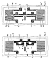
- a device is shown, which is switched in principle according to the representation in Fig. 1 and with which the error can be reduced due to a non-ideal loading of the converter.
- the deformation mechanism of the converter body 10 is influenced in an uncontrollable manner. This also applies to additional force components that do not act in the measuring direction.
- strain gauges arrangements R3 and R6 or R4 and R5 are provided in the bridge branches 1-5 and 2-5, respectively, connected to the resistor R7 in the bridge branches, with which the center of the lattice geometry of the effective part of the strain gauges opposite the transducer body 10 can apparently be displaced, thereby reducing the sensitivity of the transmitter to a non-ideal introduction of force or a non-ideal placement of the strain gauges.
- the strain gauges R3 and R4 have connection points 1 and 4 or 2 and 6.
- the connection points 4 and 6 are connected to connection points 11 and 12 of the adjustable resistor R7.
- the strain gauges R3 and R4 are each connected to strain gauges R5 and R6, which in the example have the connection points 5 or 5 'as output connections.
- the adjustable resistor R7 is designed as a film resistor which is arranged on the essentially undeformed part of the converter body 10 and whose resistance value can be changed by separating webs or abrasive processing.
- the strain gauges R3 to R6 and the adjustable resistor R7 have a common carrier film 11 for arrangement on the converter body 10.
- the creep error or a temperature-dependent creep error of a converter can be reduced with the device according to FIG. 3.
- Creep is the change in the converter signal over time with constant load.
- the creep of a strain gauge is essentially dependent on the number and design of the reversal points of the strain gauge.
- the creep of the converter is to be regarded as a superimposition of the creep from the converter body 10 and strain gauges.
- the strain gauge sections R3 ', R3 ⁇ and R4', R4 ⁇ which are arranged like the strain gauges R3 and R4 in Fig. 1 in the measuring bridge, are shaped as long, slim meanders that have positive creep.
- the strain gauge sections R5 and R6 are short, a large number of reversal points pointing meanders, which results in negative creep. With the setting of the resistor R7, the creep error influences of the strain gauge arrangements on the output signal U A can be set in a simple and effective manner.
- the adjustable resistor R7 can be designed as a temperature-dependent resistor.
- the left half-bridge in FIG. 1 can be designed like the right half-bridge, the resistance values having to be selected appropriately for the purpose of coarse and fine adjustment.
- One half-bridge can also be designed to reduce the creep error and the other half-bridge can be designed to reduce the incorrect loading error.
- the basic arrangement of the arrangement sections or the strain gauges R5 and R6 and the adjustable resistor R7 shown in FIG. 1 can advantageously also be used to reduce temperature-dependent errors.
Landscapes
- Physics & Mathematics (AREA)
- General Physics & Mathematics (AREA)
- Measurement Of Length, Angles, Or The Like Using Electric Or Magnetic Means (AREA)
- Measurement Of Force In General (AREA)
- Transmission And Conversion Of Sensor Element Output (AREA)
Applications Claiming Priority (2)
| Application Number | Priority Date | Filing Date | Title |
|---|---|---|---|
| DE3810456 | 1988-03-26 | ||
| DE3810456A DE3810456C2 (de) | 1988-03-26 | 1988-03-26 | Verfahren zur Verringerung eines Fehlers eines Meßumformers und Einrichtung hierzu |
Publications (3)
| Publication Number | Publication Date |
|---|---|
| EP0339191A2 true EP0339191A2 (fr) | 1989-11-02 |
| EP0339191A3 EP0339191A3 (fr) | 1991-07-03 |
| EP0339191B1 EP0339191B1 (fr) | 1994-01-19 |
Family
ID=6350867
Family Applications (1)
| Application Number | Title | Priority Date | Filing Date |
|---|---|---|---|
| EP89102229A Expired - Lifetime EP0339191B1 (fr) | 1988-03-26 | 1989-02-09 | Dispositif pour détruire la marge d'erreur d'un système de mesure |
Country Status (3)
| Country | Link |
|---|---|
| EP (1) | EP0339191B1 (fr) |
| JP (1) | JPH01311202A (fr) |
| DE (2) | DE3810456C2 (fr) |
Cited By (4)
| Publication number | Priority date | Publication date | Assignee | Title |
|---|---|---|---|---|
| EP0524855A1 (fr) * | 1991-07-26 | 1993-01-27 | Schlumberger Limited | Circuit électrique tel qu'un pont de wheatstone pourvu d'une partie d'ajustage de resistance |
| EP0580884A1 (fr) * | 1992-07-28 | 1994-02-02 | Hottinger Baldwin Messtechnik Gmbh | Capteur de position inductif |
| EP1347273A1 (fr) * | 2002-03-23 | 2003-09-24 | Soehnle-Waagen GmbH & Co. KG | Capteur de pesage |
| CN116718101A (zh) * | 2023-05-25 | 2023-09-08 | 中国矿业大学 | 一种rfid微带贴片天线小型化无源无线应变传感器 |
Families Citing this family (4)
| Publication number | Priority date | Publication date | Assignee | Title |
|---|---|---|---|---|
| US5929390A (en) † | 1994-09-14 | 1999-07-27 | Ishida Co., Ltd. | Load cell weighing apparatus using the same |
| DE19643868A1 (de) * | 1996-10-30 | 1998-05-07 | Rene Baltus | Wägezellenanordnung |
| DE102014206759A1 (de) * | 2014-04-08 | 2015-10-08 | Schaeffler Technologies AG & Co. KG | Messelement und ein Messelement aufweisendes Bauteil |
| CN108007334B (zh) * | 2017-12-08 | 2020-01-24 | 中国航空工业集团公司北京长城计量测试技术研究所 | 一种电阻应变测量仪的阶跃响应特性测量方法及装置 |
Family Cites Families (18)
| Publication number | Priority date | Publication date | Assignee | Title |
|---|---|---|---|---|
| US3161821A (en) * | 1962-07-02 | 1964-12-15 | Statham Instrument Inc | Wheatstone bridge transducer circuits with external balancing means |
| US3759093A (en) * | 1971-11-10 | 1973-09-18 | E Farr | Linear load cell bridge including a non-linear strain sensitive element |
| US3922597A (en) * | 1972-10-31 | 1975-11-25 | Toyoda Chuo Kenkyusho Kk | Circuit for detecting a physical quantity |
| GB2009947B (en) * | 1977-09-28 | 1982-03-24 | Itt | Bridge circuit |
| DE2839617C2 (de) * | 1978-09-12 | 1984-11-29 | Siemens AG, 1000 Berlin und 8000 München | Meßanordnung |
| US4300395A (en) * | 1978-11-08 | 1981-11-17 | Tokyo Shibaura Denki Kabushiki Kaisha | Semiconductor pressure detection device |
| DE2916390C2 (de) * | 1979-04-23 | 1982-05-27 | Siemens AG, 1000 Berlin und 8000 München | Brückenschaltung zur Messung mechanischer Spannungen einer Dehnungsmeßfeder |
| DE2916427C2 (de) * | 1979-04-23 | 1987-02-12 | Hottinger Baldwin Messtechnik Gmbh, 6100 Darmstadt | Meßumformer mit einer Feder und einer darauf applizierten Dehnungsmeßstreifenanordnung |
| US4331035A (en) * | 1979-11-13 | 1982-05-25 | Gould Inc. | Geometric balance adjustment of thin film strain gage sensors |
| US4428976A (en) * | 1979-11-13 | 1984-01-31 | Gould Inc. | Geometric balance adjustment of thin film strain gage sensors |
| DE3042506C2 (de) * | 1980-11-11 | 1986-10-09 | Gould Inc., Rolling Meadows, Ill. | Dehnungsmeßstreifenwandler |
| DE3322148C2 (de) * | 1982-01-28 | 1987-02-19 | Siemens AG, 1000 Berlin und 8000 München | Widerstandsbrückenschaltung mit einem Zeitteilerwiderstand |
| DE3330879A1 (de) * | 1983-08-26 | 1985-03-14 | Siemens AG, 1000 Berlin und 8000 München | Elektromechanischer sensor zur kraftmessung |
| DE3404936A1 (de) * | 1984-02-11 | 1985-08-14 | Bizerba-Werke Wilhelm Kraut GmbH & Co KG, 7460 Balingen | Elektromechanische waegezelle mit biegemesskoerper |
| DE3425147C2 (de) * | 1984-07-07 | 1986-06-12 | Hottinger Baldwin Messtechnik Gmbh, 6100 Darmstadt | Anordnung zur Verringerung des Einflusses des Kriechfehlers auf das Meßsignal bei Dehnungsmeßstreifen-Aufnehmern |
| DE3528510A1 (de) * | 1984-09-07 | 1986-03-20 | Hottinger Baldwin Messtechnik Gmbh, 6100 Darmstadt | Dehnungsmessstreifen-aufnehmer |
| US4672853A (en) * | 1984-10-30 | 1987-06-16 | Burr-Brown Corporation | Apparatus and method for a pressure-sensitive device |
| DE3508610C2 (de) * | 1985-03-11 | 1987-03-05 | Lothar Dipl.-Phys. Dr. 8031 Gilching Schmieder | Schaltungsanordnung für Dehnungsmeßstreifen |
-
1988
- 1988-03-26 DE DE3810456A patent/DE3810456C2/de not_active Expired - Fee Related
- 1988-12-22 JP JP63322235A patent/JPH01311202A/ja active Pending
-
1989
- 1989-02-09 EP EP89102229A patent/EP0339191B1/fr not_active Expired - Lifetime
- 1989-02-09 DE DE89102229T patent/DE58906724D1/de not_active Expired - Fee Related
Cited By (6)
| Publication number | Priority date | Publication date | Assignee | Title |
|---|---|---|---|---|
| EP0524855A1 (fr) * | 1991-07-26 | 1993-01-27 | Schlumberger Limited | Circuit électrique tel qu'un pont de wheatstone pourvu d'une partie d'ajustage de resistance |
| FR2679662A1 (fr) * | 1991-07-26 | 1993-01-29 | Schlumberger Services Petrol | Circuit electrique tel qu'un pont de wheatstone pourvu d'une partie d'ajustage de resistance. |
| US5309136A (en) * | 1991-07-26 | 1994-05-03 | Schlumberger Technology Corporation | Electrical circuit such as a Wheatstone bridge with a resistance-adjusting portion |
| EP0580884A1 (fr) * | 1992-07-28 | 1994-02-02 | Hottinger Baldwin Messtechnik Gmbh | Capteur de position inductif |
| EP1347273A1 (fr) * | 2002-03-23 | 2003-09-24 | Soehnle-Waagen GmbH & Co. KG | Capteur de pesage |
| CN116718101A (zh) * | 2023-05-25 | 2023-09-08 | 中国矿业大学 | 一种rfid微带贴片天线小型化无源无线应变传感器 |
Also Published As
| Publication number | Publication date |
|---|---|
| JPH01311202A (ja) | 1989-12-15 |
| DE58906724D1 (de) | 1994-03-03 |
| DE3810456A1 (de) | 1989-10-05 |
| EP0339191A3 (fr) | 1991-07-03 |
| DE3810456C2 (de) | 1994-09-01 |
| EP0339191B1 (fr) | 1994-01-19 |
Similar Documents
| Publication | Publication Date | Title |
|---|---|---|
| EP0274767B1 (fr) | Méthode et circuit pour determiner la position d'une prise d'un transmetteur de résistance à distance | |
| DE2916427A1 (de) | Aufnehmer mit einer feder und einer darauf applizierten dehnungsmesstreifenanordnung | |
| EP0339191B1 (fr) | Dispositif pour détruire la marge d'erreur d'un système de mesure | |
| DE2701857C2 (fr) | ||
| DE2853829A1 (de) | Differenzverstaerkeranordnung | |
| DE3901314C2 (fr) | ||
| EP0514634A1 (fr) | Procédé de correction des erreurs de mesure | |
| EP0929818A1 (fr) | Circuit electrique pour determiner un courant de charge | |
| DE2659359A1 (de) | Messgeraet zur automatischen bestimmung des prozentualen fehlers des werts eines widerstandes | |
| EP3828564B1 (fr) | Validation des courants de phase d'un système multi-phase | |
| DE3634053A1 (de) | Verfahren und schaltungsanordnung zur messung der widerstandswerte zweier in reihe geschalteter sensorwiderstaende | |
| DE102018216131B4 (de) | Verfahren und Vorrichtung zur gleichzeitigen Bestimmung der Temperatur- und Widerstandsänderung von Sensorwiderständen einer als Viertel- oder Halbbrücke ausgebildeten Brückenschaltung | |
| DE2460079B2 (de) | Verfahren zur Bestimmung der Stellung des Schleifen eines Potentiometers und Schaltungsanordnung zur Durchführung des Verfahrens | |
| DE19723248B4 (de) | Kompakter Aufbau für eine selbstregelnde Verstärkerschaltung | |
| EP0456168A2 (fr) | Dispositif de conversion analogue-digitale d'un grandeur de mesure, engendré par des transducteurs disposés dans un circuit à pont, en particulier par des jauges de contrainte dans une cellule de pesage | |
| DE3908795A1 (de) | Verfahren und vorrichtung zur messung einer mechanischen verformung | |
| DE4244394C2 (de) | Schnittstelle bei eichfähigen elektromechanischen Waagen | |
| DE3322148C2 (de) | Widerstandsbrückenschaltung mit einem Zeitteilerwiderstand | |
| EP0573808A2 (fr) | Transducteur de force | |
| DD288046A5 (de) | Verstaerkerschaltungsanordnung in einem ad-umsetzer | |
| EP1457767A1 (fr) | Mesure d'une pression avec un pont et une tension réduite pour le convertisseur A/D | |
| DE4227764A1 (de) | Sensor zum Erfassen mechanischer Belastungen | |
| DE3032777C2 (de) | Anordnung zum Empfindlichkeitsausgleich des Indikators in Meßbrückenschaltungen | |
| DE2856285C3 (fr) | ||
| DE2856285A1 (de) | Chaltungsanordnung fuer den nullabgleich von messbruecken |
Legal Events
| Date | Code | Title | Description |
|---|---|---|---|
| PUAI | Public reference made under article 153(3) epc to a published international application that has entered the european phase |
Free format text: ORIGINAL CODE: 0009012 |
|
| AK | Designated contracting states |
Kind code of ref document: A2 Designated state(s): DE FR GB |
|
| PUAL | Search report despatched |
Free format text: ORIGINAL CODE: 0009013 |
|
| AK | Designated contracting states |
Kind code of ref document: A3 Designated state(s): DE FR GB |
|
| 17P | Request for examination filed |
Effective date: 19910822 |
|
| 17Q | First examination report despatched |
Effective date: 19920916 |
|
| GRAA | (expected) grant |
Free format text: ORIGINAL CODE: 0009210 |
|
| AK | Designated contracting states |
Kind code of ref document: B1 Designated state(s): DE FR GB |
|
| GBT | Gb: translation of ep patent filed (gb section 77(6)(a)/1977) |
Effective date: 19940118 |
|
| REF | Corresponds to: |
Ref document number: 58906724 Country of ref document: DE Date of ref document: 19940303 |
|
| ET | Fr: translation filed | ||
| PLBE | No opposition filed within time limit |
Free format text: ORIGINAL CODE: 0009261 |
|
| STAA | Information on the status of an ep patent application or granted ep patent |
Free format text: STATUS: NO OPPOSITION FILED WITHIN TIME LIMIT |
|
| 26N | No opposition filed | ||
| REG | Reference to a national code |
Ref country code: GB Ref legal event code: IF02 |
|
| PGFP | Annual fee paid to national office [announced via postgrant information from national office to epo] |
Ref country code: FR Payment date: 20030113 Year of fee payment: 15 |
|
| PGFP | Annual fee paid to national office [announced via postgrant information from national office to epo] |
Ref country code: GB Payment date: 20030116 Year of fee payment: 15 |
|
| PGFP | Annual fee paid to national office [announced via postgrant information from national office to epo] |
Ref country code: DE Payment date: 20030422 Year of fee payment: 15 |
|
| PG25 | Lapsed in a contracting state [announced via postgrant information from national office to epo] |
Ref country code: GB Free format text: LAPSE BECAUSE OF NON-PAYMENT OF DUE FEES Effective date: 20040209 |
|
| PG25 | Lapsed in a contracting state [announced via postgrant information from national office to epo] |
Ref country code: DE Free format text: LAPSE BECAUSE OF NON-PAYMENT OF DUE FEES Effective date: 20040901 |
|
| GBPC | Gb: european patent ceased through non-payment of renewal fee |
Effective date: 20040209 |
|
| PG25 | Lapsed in a contracting state [announced via postgrant information from national office to epo] |
Ref country code: FR Free format text: LAPSE BECAUSE OF NON-PAYMENT OF DUE FEES Effective date: 20041029 |
|
| REG | Reference to a national code |
Ref country code: FR Ref legal event code: ST |