EP0339207B1 - Kupplung mit einem viskosen Fluid (Viskofluidkupplung) - Google Patents
Kupplung mit einem viskosen Fluid (Viskofluidkupplung) Download PDFInfo
- Publication number
- EP0339207B1 EP0339207B1 EP89103593A EP89103593A EP0339207B1 EP 0339207 B1 EP0339207 B1 EP 0339207B1 EP 89103593 A EP89103593 A EP 89103593A EP 89103593 A EP89103593 A EP 89103593A EP 0339207 B1 EP0339207 B1 EP 0339207B1
- Authority
- EP
- European Patent Office
- Prior art keywords
- shaft
- casing
- viscous fluid
- working chamber
- multistep
- Prior art date
- Legal status (The legal status is an assumption and is not a legal conclusion. Google has not performed a legal analysis and makes no representation as to the accuracy of the status listed.)
- Expired - Lifetime
Links
Images

Classifications
-
- F—MECHANICAL ENGINEERING; LIGHTING; HEATING; WEAPONS; BLASTING
- F16—ENGINEERING ELEMENTS AND UNITS; GENERAL MEASURES FOR PRODUCING AND MAINTAINING EFFECTIVE FUNCTIONING OF MACHINES OR INSTALLATIONS; THERMAL INSULATION IN GENERAL
- F16D—COUPLINGS FOR TRANSMITTING ROTATION; CLUTCHES; BRAKES
- F16D35/00—Fluid clutches in which the clutching is predominantly obtained by fluid adhesion
- F16D35/005—Fluid clutches in which the clutching is predominantly obtained by fluid adhesion with multiple lamellae
Definitions
- the present invention relates to a viscous fluid coupling used for four-wheel drive vehicles, for instance, and more specifically to a viscous fluid coupling for transmitting power via viscous resistance of viscous fluid applied to a plurality of resistance plates arranged within a working chamber of the apparatus.
- viscous fluid coupling is disclosed as a viscous coupling apparatus in Japanese Published Unexamined (Kokai) Patent Appli. No. 58-50349.
- a plurality of resistance plates are arranged on the casing side and the shaft side, respectively along the axial direction thereof so as to be alternately opposite to each other and extend in the radical direction thereof within a working chamber filled with a viscous fluid (e.g. silicon oil). Therefore, when either of the casing or shaft is rotated, power is transmitted from one to the other via fluid viscous resistance generated by relative rotation between these resistance plates.
- a viscous fluid e.g. silicon oil
- the working chamber is airtightly formed by sealing members disposed between the casing and two accel shafts and further the resistance plates fixed to the shaft side within the working chamber filled with viscous fluid are arranged along splines formed on the outer circumferential surface of an end of each of the two accel shafts. Therefore, it has been impossible to subassemble the apparatus after the viscous fluid is put into the working chamber. In other words, since the viscous fluid is put after the resistance plates have been assembled and further the sealing members have been attached during vehicle assembly process, there exists a problem in that vehicle assembly work is complicated and therefore vehicle assembly reliability is deteriorated.
- the working chamber is formed by an outer cylindrical member, two side flanges formed integral with the outer cylindrical member on both the sides thereof, and a hub arranged on the inner circumferential side of the side flanges.
- a plurality of resistance plates are arranged along the axial direction and alternately fixed to the inner circumferential wall of the outer cylindrical member and the outer circumferential surface of the hub so as to extend in the radical direction within a working chamber filled with viscous fluid.
- the inner circumference of the hub is linked with an input shaft to which power is applied and further loosely fitted to the side flanges. Sealing members are disposed at the fitting portion between the hub and the side flanges to form an airtight working chamber.
- the above-mentioned second prior-art viscous coupling apparatus has such an advantage as to enable the apparatus to be subassembled; however, since a hub is provided along the axial direction, there exists another problem in that the volume or the radical length of the working chamber is reduced and therefore it is difficult to obtain desired performance. To overcome this problem when the axial length of the working chamber is increased, the apparatus is inevitably increased both in size and weight.
- a viscous fluid coupling in accordance with the preamble of claim 1 is known from DE-A-3708054. This document discloses a viscous coupling which is arranged adjacent to a gear drive so that the heating produced by the internal friction of the viscous fluid coupling can be transferred to the environment and that the bearings and joints can be connected to the lubricant supply of the gear.
- the present invention has the object to provide a viscous fluid coupling which is easy to manufacture and assemble and small in size, while enabling sub-assembly thereof.
- FIG. 1 is an illustration showing and entire four-wheel drive system to which the viscous fluid coupling according to the present invention is applied.
- an engine 1 and a transmission 3 are arranged along the lateral direction and on the front side of the vehicle.
- An output (wheel drive power) obtained through the transmission 3 is transmitted to the right and left front wheels 7 via a transfer 5, and further to the right and left rear wheels 15 via a viscous coupling apparatus 9, a propeller shaft 11 and a final drive unit 13.
- the viscous coupling apparatus 9 for transmitting power has such a function that a small torque is transmitted from an input shaft to an output shaft when difference in the number of rotation between the two shafts is small, but a large torque is transmitted when the difference is large.
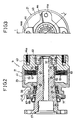
- the viscous coupling apparatus 9 comprises a shaft 19 formed with a flange 17 serving as a first connecting portion (to which an input power is applied), a casing 21 rotatably fitted to the outer circumference of the shaft 19, and an airtight working chamber 23 formed between the shaft 19 and the casing 21.
- This flange portion 17 is fixed to an output shaft of the transfer 5, in practice.
- the shaft 19 is formed into multistep or multishoulder shape composed of a first step portion 25, a second step portion 27, a third step portion 29, a fourth step portion 31, a fifth step portion 33, a sixth step portion 35 and a seventh step portion in such a way that the diameters of these step portions are reduced step by step from the flange 17 formed at one (input) end thereof to the other (output) end thereof.
- the casing 21 is formed with an outer cylindrical portion 41 having a flange portion 39, and an output member 43 is fitted to the open end of the outer cylindrical portion 41 and fixed thereto by welding, for instance. As shown in Fig.
- the output member 43 is formed with a boss portion 44 having four threaded portions 44a and serving as a second connecting portion (from which an output power is transmitted).
- This boss portion 44 is connected to the propeller shaft 11 via a flange portion of a universal joint (not shown), in practice.
- the casing 21 is fitted to the shaft 19 from the output end side, and rotatably supported by the shaft 19 in such a way that an annular projection 45 of the flange portion 39 of the casing 21 is supported by the third step portion 29 of the shaft 19 via a bearing 47 and further the output member 43 is supported by the seventh step portion 37 of the shaft 19 via another bearing 49.
- a sealing member 51 is provided between the fourth step portion 31 of the shaft 19 and the flange portion 39 of the casing 21 and further another sealing member 53 is provided between the sixth step portion 35 of the shaft 19 and the output member 43, so that a working chamber 23 is airtightly formed so as to be filled with a viscous fluid such as silicon oil.
- a plurality of resistance plates 57 engaged with splines 55 formed in the inner circumferential wall of the outer cylindrical member 41 of the casing 21 and another plurality of resistance plates 61 engaged with splines 59 formed in the outer circumferential surface of the fifth step portion 33 of the shaft 19 are alternately arranged so as to intervene between the two other resistant plates.
- plural locating spacer rings 63 are disposed between the two resistance plates 57 spline engaged with the casing 21 to maintain a predetermined distance therebetween in such a way as to be separated away from the outer circumference of the resistance plates 61 spline engaged with the shaft 19.
- the shaft 19 is formed into a hollow shaft formed with an axial through bore 65 in order to reduce the weight thereof.
- a sealing member 69 is disposed between the second step portion 27 of the shaft 19 and a flange portion 67 of an annular projection 45 of the casing 2 without preventing the relative rotation between the shaft 19 and the casing 21.
- the reference numeral 71 denotes a dust cover disposed in contact with a lip portion of the sealing member 69.
- a power of the engine 1 is transmitted to the front wheels 7 via the transmission 3 and the transfer 5 and, on the other hand, to the rear wheels 15 via the viscous coupling (power transmission) apparatus 9, the propeller shaft 11 and the final drive unit 13.
- a rotational power inputted from the transfer 5 to the shaft 19 of the viscous coupling apparatus 9 is transmitted from the resistance plates 61 rotatable integral with the shaft 19 to the resistance plates 57 rotatable integral with the casing 21 via a viscous resistance of fluid filling the working chamber 23, and further transmitted to the propeller shaft 11 connected to the output member 43 via a universal joint.
- the working chamber 23 filled with viscous fluid is formed between a step portion (the fifth step portion 33 in this embodiment) and the casing 21, and further plural resistance plates 57 engage with the splines 55 formed in the inner circumferential wall of the casing 21 and plural resistance plates 61 engaged with the splines 59 formed in the outer circumferential surface of the fifth step portion 33 of the shaft 19 are alternately arranged one by one, it is unnecessary to provide a hub member on the shaft side as in the prior-art apparatus. Therefore, the viscous coupling apparatus can be subassembled as a unit, so that it is possible to simplify the assembly work of the apparatus to a vehicle body as shown in Fig. 1.
- the volume or the radial length of the working chamber 23 is not reduced. Therefore, it is possible to increase the volume of the working chamber 23 without increasing the axial length thereof or to reduce the size of the apparatus.
- a shaft having a first connecting portion on one (input) end side and a multistep portion on the other (output) end side, a working chamber formed between the shaft and the casing fitted to the shaft from the other (output) end side and filled with viscous fluid, and two sets of plural resistance plates alternately spline engaged with the casing and the shaft within the working chamber, it is possible to subassemble the apparatus in the state where the working chamber is filled with viscous fluid, thus facilitating the vehicle assembly work.
- the plural resistance plates are directly engaged with a certain step portion of the shaft, it is possible to eliminate the use of the conventional hub and therefore to reduce the volume or the size of the apparatus.
Landscapes
- Engineering & Computer Science (AREA)
- General Engineering & Computer Science (AREA)
- Mechanical Engineering (AREA)
- Arrangement And Driving Of Transmission Devices (AREA)
- Artificial Filaments (AREA)
- Soy Sauces And Products Related Thereto (AREA)
- Seal Device For Vehicle (AREA)
Claims (3)
- Viskofluidkupplung mit:- einer Welle (19), die mit einem ersten Verbindungsteil (17) an einem ersten Ende von dieser ausgebildet ist;- einem Gehäuse (21), welches mit einem zweiten Verbindungsbereich (43) an einem zweiten Ende der Welle ausgebildet ist, entgegengesetzt zu dem ersten Ende und welches so an der Welle (19) angeordnet ist, daß eine Arbeitskammer (23) gebildet wird, zwischen der Welle (19) und dem Gehäuse (21);- einer Vielzahl von ersten Widerstandsplatten (61), welche im Eingriff mit der Welle stehen und entlang der axialen Richtung der Welle (19) innerhalb der Arbeitskammer (23) angeordnet sind; und- einer Vielzahl von zweiten Widerstandsplatten (57), welche im Eingriff mit dem Gehäuse (21) stehen und entlang einer axialen Richtung von diesem innerhalb der Arbeitskammer (23) angeordnet sind, und zwar derart, daß die ersten und die zweiten Widerstandsplatten (61, 57) alternativ derart angeordnet sind, so daß sich jede zwischen zwei der anderen Widerstandsplatten befindet,dadurch gekennzeichnet,
daß die Welle (19) mit einem mehrfach abgestuften Schulterbereich (25,27,29,31,33,35,37) ausgebildet ist, welche in enger Durchmesserabstufung gegen das zweite Ende hin ausgebildet ist, und daß das Gehäuse (21) von dem zweiten Ende der Vielfachstufenwelle aus auf diese aufgepaßt ist, um die Montage der Viskofluidkupplung ohne Verwendung von irgendeiner Nabe zu erleichtern. - Viskofluidkupplung gemäß Anspruch 1, wobei der erste Verbindungsteil (17) der vielfach gestuften Welle (19) ein Eingangsbereich ist, auf welchen eine Leistung aufgebracht wird.
- Viskofluidkupplung gemäß Anspruch 1, wobei der zweite Verbindungsteil (43) des Gehäuses (21) ein Ausgangsteil ist, von welchem Leistung nach außen übertragen wird.
Priority Applications (1)
| Application Number | Priority Date | Filing Date | Title |
|---|---|---|---|
| AT89103593T ATE81391T1 (de) | 1988-03-01 | 1989-03-01 | Kupplung mit einem viskosen fluid (viskofluidkupplung). |
Applications Claiming Priority (2)
| Application Number | Priority Date | Filing Date | Title |
|---|---|---|---|
| JP45746/88 | 1988-03-01 | ||
| JP63045746A JP2621117B2 (ja) | 1988-03-01 | 1988-03-01 | 動力伝達装置 |
Publications (2)
| Publication Number | Publication Date |
|---|---|
| EP0339207A1 EP0339207A1 (de) | 1989-11-02 |
| EP0339207B1 true EP0339207B1 (de) | 1992-10-07 |
Family
ID=12727879
Family Applications (1)
| Application Number | Title | Priority Date | Filing Date |
|---|---|---|---|
| EP89103593A Expired - Lifetime EP0339207B1 (de) | 1988-03-01 | 1989-03-01 | Kupplung mit einem viskosen Fluid (Viskofluidkupplung) |
Country Status (5)
| Country | Link |
|---|---|
| US (1) | US4928803A (de) |
| EP (1) | EP0339207B1 (de) |
| JP (1) | JP2621117B2 (de) |
| AT (1) | ATE81391T1 (de) |
| DE (1) | DE68903127T2 (de) |
Families Citing this family (4)
| Publication number | Priority date | Publication date | Assignee | Title |
|---|---|---|---|---|
| US5176235A (en) * | 1991-04-19 | 1993-01-05 | New Venture Gear, Inc. | Viscous coupling apparatus |
| US5363948A (en) * | 1993-01-19 | 1994-11-15 | Milemarker, Inc. | Selective drive fluid coupling |
| US5593012A (en) * | 1993-01-19 | 1997-01-14 | Milemarker, Inc. | Limited fixed torque slip coupling |
| US5431603A (en) * | 1993-07-06 | 1995-07-11 | Milemarker, Inc. | Transfer case having selective drive fluid coupling |
Family Cites Families (9)
| Publication number | Priority date | Publication date | Assignee | Title |
|---|---|---|---|---|
| US3380565A (en) * | 1966-02-03 | 1968-04-30 | Mobil Oil Corp | Clutch |
| US3390748A (en) * | 1966-12-27 | 1968-07-02 | Borg Warner | Fluid shear coupling |
| JPS595240Y2 (ja) * | 1979-02-08 | 1984-02-16 | アイシン精機株式会社 | 温度感応式粘性流体継手装置 |
| DE3269958D1 (en) * | 1981-06-26 | 1986-04-24 | Ferguson Ltd Harry | Differential drive arrangement |
| US4690258A (en) * | 1985-05-27 | 1987-09-01 | Tochigifujisangyo Kabushikigaisha | Hydraulic power transmission device with centrifugally actuated clutch override |
| JPS61294224A (ja) * | 1985-06-20 | 1986-12-25 | Tochigi Fuji Ind Co Ltd | カツプリング装置 |
| AT383196B (de) * | 1985-07-16 | 1987-05-25 | Steyr Daimler Puch Ag | Fluessigkeitsreibungskupplung |
| US4782930A (en) * | 1986-02-04 | 1988-11-08 | Tochigifujisangyo Kabushiki Kaisha | Power transmission apparatus |
| JPH034834Y2 (de) * | 1986-03-14 | 1991-02-07 |
-
1988
- 1988-03-01 JP JP63045746A patent/JP2621117B2/ja not_active Expired - Fee Related
-
1989
- 1989-02-27 US US07/316,287 patent/US4928803A/en not_active Expired - Lifetime
- 1989-03-01 EP EP89103593A patent/EP0339207B1/de not_active Expired - Lifetime
- 1989-03-01 DE DE8989103593T patent/DE68903127T2/de not_active Expired - Fee Related
- 1989-03-01 AT AT89103593T patent/ATE81391T1/de active
Also Published As
| Publication number | Publication date |
|---|---|
| US4928803A (en) | 1990-05-29 |
| JPH01224527A (ja) | 1989-09-07 |
| EP0339207A1 (de) | 1989-11-02 |
| ATE81391T1 (de) | 1992-10-15 |
| JP2621117B2 (ja) | 1997-06-18 |
| DE68903127D1 (de) | 1992-11-12 |
| DE68903127T2 (de) | 1993-02-25 |
Similar Documents
| Publication | Publication Date | Title |
|---|---|---|
| US4650028A (en) | Viscous coupling apparatus for on-demand four wheel drive system | |
| US4982808A (en) | Viscous shear coupling | |
| US4601359A (en) | Part time on-demand four-wheel drive vehicle transaxle with viscous clutch | |
| KR100508014B1 (ko) | 복수의챔버를갖는자동차구동라인차동장치 | |
| US5056640A (en) | Torque transmission device for a four-wheel drive vehicle | |
| JPH0237034A (ja) | 駆動力配分装置 | |
| EP0381505A1 (de) | Kontrollkupplung zur Drehmomentübertragung | |
| EP0893613B1 (de) | Kardanwelle | |
| EP0314420A1 (de) | Aufbau einer Flüssigkeitsreibungskupplung zum Übertragen eines Drehmoments in einem Kraftfahrzeug | |
| JP2597250B2 (ja) | 四輪駆動車用の駆動装置 | |
| US4900042A (en) | Fluid sealing structure | |
| JP2941077B2 (ja) | 四輪駆動車用駆動力伝達装置 | |
| US4712663A (en) | Viscous coupling for a drive shaft | |
| EP1239191B1 (de) | Differentialeinheit | |
| US5176235A (en) | Viscous coupling apparatus | |
| US4981192A (en) | Power transmission apparatus | |
| US4928803A (en) | Power transmission apparatus | |
| US5101678A (en) | Coupling device for power transfer | |
| JP3844532B2 (ja) | デファレンシャル装置 | |
| JP3641519B2 (ja) | デファレンシャル装置 | |
| CN100447446C (zh) | 用于动力传动装置的连接结构与连接方法 | |
| US5133438A (en) | Viscous coupling with spacer rings | |
| US4983150A (en) | Differential gear apparatus with differential limitation mechanism | |
| JP2554060Y2 (ja) | ビスカスカップリング装置 | |
| JP2638986B2 (ja) | ビスカスカップリング装置 |
Legal Events
| Date | Code | Title | Description |
|---|---|---|---|
| PUAI | Public reference made under article 153(3) epc to a published international application that has entered the european phase |
Free format text: ORIGINAL CODE: 0009012 |
|
| 17P | Request for examination filed |
Effective date: 19890301 |
|
| AK | Designated contracting states |
Kind code of ref document: A1 Designated state(s): AT DE FR GB IT |
|
| 17Q | First examination report despatched |
Effective date: 19910305 |
|
| GRAA | (expected) grant |
Free format text: ORIGINAL CODE: 0009210 |
|
| AK | Designated contracting states |
Kind code of ref document: B1 Designated state(s): AT DE FR GB IT |
|
| REF | Corresponds to: |
Ref document number: 81391 Country of ref document: AT Date of ref document: 19921015 Kind code of ref document: T |
|
| ITF | It: translation for a ep patent filed | ||
| REF | Corresponds to: |
Ref document number: 68903127 Country of ref document: DE Date of ref document: 19921112 |
|
| ET | Fr: translation filed | ||
| PLBE | No opposition filed within time limit |
Free format text: ORIGINAL CODE: 0009261 |
|
| STAA | Information on the status of an ep patent application or granted ep patent |
Free format text: STATUS: NO OPPOSITION FILED WITHIN TIME LIMIT |
|
| 26N | No opposition filed | ||
| PGFP | Annual fee paid to national office [announced via postgrant information from national office to epo] |
Ref country code: AT Payment date: 19990324 Year of fee payment: 11 |
|
| PG25 | Lapsed in a contracting state [announced via postgrant information from national office to epo] |
Ref country code: AT Free format text: LAPSE BECAUSE OF NON-PAYMENT OF DUE FEES Effective date: 20000301 |
|
| REG | Reference to a national code |
Ref country code: GB Ref legal event code: IF02 |
|
| PGFP | Annual fee paid to national office [announced via postgrant information from national office to epo] |
Ref country code: GB Payment date: 20050223 Year of fee payment: 17 |
|
| PGFP | Annual fee paid to national office [announced via postgrant information from national office to epo] |
Ref country code: DE Payment date: 20050224 Year of fee payment: 17 |
|
| PG25 | Lapsed in a contracting state [announced via postgrant information from national office to epo] |
Ref country code: IT Free format text: LAPSE BECAUSE OF NON-PAYMENT OF DUE FEES;WARNING: LAPSES OF ITALIAN PATENTS WITH EFFECTIVE DATE BEFORE 2007 MAY HAVE OCCURRED AT ANY TIME BEFORE 2007. THE CORRECT EFFECTIVE DATE MAY BE DIFFERENT FROM THE ONE RECORDED. Effective date: 20050301 |
|
| PGFP | Annual fee paid to national office [announced via postgrant information from national office to epo] |
Ref country code: FR Payment date: 20050308 Year of fee payment: 17 |
|
| PG25 | Lapsed in a contracting state [announced via postgrant information from national office to epo] |
Ref country code: GB Free format text: LAPSE BECAUSE OF NON-PAYMENT OF DUE FEES Effective date: 20060301 |
|
| PG25 | Lapsed in a contracting state [announced via postgrant information from national office to epo] |
Ref country code: DE Free format text: LAPSE BECAUSE OF NON-PAYMENT OF DUE FEES Effective date: 20061003 |
|
| GBPC | Gb: european patent ceased through non-payment of renewal fee |
Effective date: 20060301 |
|
| REG | Reference to a national code |
Ref country code: FR Ref legal event code: ST Effective date: 20061130 |
|
| PG25 | Lapsed in a contracting state [announced via postgrant information from national office to epo] |
Ref country code: FR Free format text: LAPSE BECAUSE OF NON-PAYMENT OF DUE FEES Effective date: 20060331 |