EP0339357A2 - Outil de coupe - Google Patents
Outil de coupe Download PDFInfo
- Publication number
- EP0339357A2 EP0339357A2 EP89106386A EP89106386A EP0339357A2 EP 0339357 A2 EP0339357 A2 EP 0339357A2 EP 89106386 A EP89106386 A EP 89106386A EP 89106386 A EP89106386 A EP 89106386A EP 0339357 A2 EP0339357 A2 EP 0339357A2
- Authority
- EP
- European Patent Office
- Prior art keywords
- cutting knife
- knife according
- blade
- holding
- blade part
- Prior art date
- Legal status (The legal status is an assumption and is not a legal conclusion. Google has not performed a legal analysis and makes no representation as to the accuracy of the status listed.)
- Granted
Links
Images


Classifications
-
- E—FIXED CONSTRUCTIONS
- E04—BUILDING
- E04F—FINISHING WORK ON BUILDINGS, e.g. STAIRS, FLOORS
- E04F21/00—Implements for finishing work on buildings
- E04F21/28—Implements for finishing work on buildings for glazing
- E04F21/32—Putty knives; Putty removers
-
- B—PERFORMING OPERATIONS; TRANSPORTING
- B23—MACHINE TOOLS; METAL-WORKING NOT OTHERWISE PROVIDED FOR
- B23D—PLANING; SLOTTING; SHEARING; BROACHING; SAWING; FILING; SCRAPING; LIKE OPERATIONS FOR WORKING METAL BY REMOVING MATERIAL, NOT OTHERWISE PROVIDED FOR
- B23D35/00—Tools for shearing machines or shearing devices; Holders or chucks for shearing tools
- B23D35/008—Means for changing the cutting members
-
- B—PERFORMING OPERATIONS; TRANSPORTING
- B26—HAND CUTTING TOOLS; CUTTING; SEVERING
- B26B—HAND-HELD CUTTING TOOLS NOT OTHERWISE PROVIDED FOR
- B26B27/00—Hand cutting tools not provided for in the preceding groups, e.g. finger rings for cutting string, devices for cutting by means of wires
-
- B—PERFORMING OPERATIONS; TRANSPORTING
- B26—HAND CUTTING TOOLS; CUTTING; SEVERING
- B26B—HAND-HELD CUTTING TOOLS NOT OTHERWISE PROVIDED FOR
- B26B5/00—Hand knives with one or more detachable blades
-
- B—PERFORMING OPERATIONS; TRANSPORTING
- B26—HAND CUTTING TOOLS; CUTTING; SEVERING
- B26B—HAND-HELD CUTTING TOOLS NOT OTHERWISE PROVIDED FOR
- B26B7/00—Hand knives with reciprocating motor-driven blades
Definitions
- the invention relates to a cutting knife for a cutting tool with a swiveling oscillating drive, as is known for example from DE-GM 80 31 084.5, in particular for severing joint seals or insulation in glass panes, the cutting knife comprising a holding part for attachment to the drive and a blade part .
- Such cutting knives are known, for example, from EP-A-0 174 427 and EP-A-0 141 035 and are also used in particular for severing the adhesive layer of a bonded pane, for example in motor vehicles, in which the windscreens in particular are used to achieve a more economical one Air resistance coefficient are glued to the body.
- the cutting tools with oscillation drive enable this adhesive layer to be cut through very quickly, so that the exchange of such damaged disks is quick. Because of the forces involved in severing the adhesive layer, it is necessary to use high quality steel for the blade.
- the previous cutting knives were designed in one piece, among other things, because of the forces occurring during the cutting. As a result, the price of a replacement blade is relatively high due to the high quality materials used.
- the object of the invention is to make the replacement of the cutting knife more economical.
- Cutting knives with interchangeable blades are known from the prior art, for. B. from EP-A 81 199, but this is always a hand-held knife, in which forces, such as occur in the cutting knife for cutting tools with oscillation drive, do not occur. Surprisingly, there are also no problems if the blade part is immersed in an adhesive layer where it is not guided.
- the greater economy of the cutting knife according to the invention results on the one hand in that the blade part is exchangeable, i.e. the part that has to be rejected affects only a part of the cutting knife and on the other hand the holding part can be made of a cheaper material, since this does not necessarily have to consist of the high quality blade steel.
- knife blades made from carpet knives can be used as blade parts. These are not only very inexpensive, but are also available everywhere. In addition, both ends of these carpet knife blades can also be used by simply turning the blade over.
- the blade part can be designed so that it only overlaps with the end of the holding part facing away from the drive and is attached to it.
- the blade part can extend over the entire length of the holding part, a bore being provided in the blade part for receiving the drive shaft. The opposite end of the blade part then forms the actual cutting blade and protrudes beyond the holding part.
- Another possibility for attaching the blade part to the holding part is the use of an intermediate piece to which the holding part or the blade part or both are exchangeably attached.
- a support stop is arranged adjacent to the cutting edge of the blade part. This can be done both on the holding part and on the blade part.
- the support stop is preferably formed from soft material, so that the cutting knife can, for example, rest against the vehicle body during the cutting process without the body being damaged thereby.
- Plastic in particular is a suitable material here, but it must have sufficient mechanical strength to withstand the mechanical loads that occur during operation of the knife.
- Preferred cutting knives are angled twice in opposite directions in their longitudinal direction, so that a bent-off blade part results.
- the blade part can only on the be cranked part of the holding part or may also have a cranked shape itself, in which case the blade part preferably extends to the drive shaft of the cutting tool and is held thereon.
- the free end of the blade part preferably runs slightly inclined to the plane of the holding part in the region of the drive shaft, for example at an angle of approximately 15 °.
- the support stop should have a slightly larger width than the surface supporting the support stop, so as to ensure that the cutting knife can be guided by the support stop on the body in any working position.
- the knife is bent back in a U-shape in the longitudinal direction.
- the U-shaped part of the knife can be realized by twisting it in the same direction twice or in a bend characterized by a radius.
- the support stop is arranged in the region of the bending of the knife. A steady transition of the support stop into the angle of the knife is advantageous here.
- the blade part and the holding part are preferably connected to one another by means of a guide element and a securing element.
- the guide element can be formed in one piece with the blade part or the holding part.
- the securing element can be formed in one piece with the blade part or the holding part.
- An example of a one-piece molded securing element on the blade part is a blade part which extends to the drive shaft and has a bore which receives the drive shaft of the cutting tool.
- the blade part is fixed flat on the holding part by means of the guide element or elements, while a displacement of the blade part relative to the holding part by the securing element, i.e. through the hole in the shaft end of the blade part for receiving the drive shaft.
- the guide elements are preferably formed longitudinally on the blade part or on the holding part, the other part being encompassed by the guide elements at least in its edge region and thus being held displaceably in the longitudinal direction.
- the guide elements can also consist of hook parts which are attached to the holding or blade part and which engage in recesses in the other part.
- the hook parts can be designed, for example, as a pin with a head part, or they can also be tabs which protrude from the plane of the holding or blade part in two opposite directions.
- the holding part and / or the blade part is conical, the tapered end pointing towards the tip of the knife. Inserting the knife into the seal to be separated is particularly easy to achieve with cutting knives designed in this way, which also preferably have cutting surfaces on both longitudinal directions of the blade part.
- the securing element can be latched in the overlap region of the holding part and the blade part, the securing element encompassing the holding and the blade part.
- the securing element is preferably designed at the same time as a support stop and is also preferably made of plastic in this case.
- the securing element is preferably via clamping means, such as set an eccentric lever or a clamping screw on the cutting knife.
- the holding part has a form-fitting receptacle for the fixing part of the blade part.
- this form-fitting receptacle is designed such that it supports the fixing part in a rotationally fixed manner.
- the blade part is connected to the holding part without play.
- the receptacle supports the fixing part at at least two points spaced apart in the longitudinal direction of the blade part.
- Such a connection is also suitable for long-term use because of its stability, since it offers a lower tendency to deflect.
- the receptacle has a projection that extends through a recess in the fixing part.
- a particularly high mechanical stability can be achieved if the receptacle has abutting surfaces on the longitudinal side surfaces of the fixing part, so that the force can be transmitted from the holding part to the blade part over as large a surface as possible and therefore the risk of knocking out is reduced again.
- the fixing part is held with a precise fit by the stop surfaces.
- a further advantage is provided by an exemplary embodiment in which it is provided that the blade part can be used in the receptacle in two different positions, so that the feature of the interchangeability of the blade part can also be used simultaneously for two different or at least partially different knife types with a holding part and to get the same blade.
- a preferred possibility provides that the blade part can be inserted into the receptacle with a different extent away from the holding part.
- a preferred embodiment provides that the recording by a base part of the holding part and one on the Base part attachable support part is formed and that the blade part between the support part and the base part is fixable. This means that the blade part can be clamped between the support part and the base part.
- the base part and the support part can be connected in a rotationally fixed manner by positive locking, so that no relative movement of the support part to the base part can take place and play based on this is eliminated from the outset .
- the positive locking is carried out by means of positive locking surfaces running parallel to the longitudinal direction of the blade part and parallel to one another.
- the form-fitting surfaces can be acted upon in the direction of a snug fit by an inclined surface arranged on the base part or on the support part and a sliding part arranged thereon, on the support part or on the base part.
- the inclined surface extends obliquely to a mounting direction of the support part.
- the holding part carries the support stop, since a reduction in costs can thus be achieved in that only the mere exchangeable blade part has to be supplied as an exchange part while the support stop together the holding part can continue to be used.
- the support stop is carried by the base part.
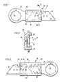
- FIGS 1 to 4 show a cutting knife 20 according to the invention, which is constructed such that a normal carpet knife can be used as the blade part 22.
- the blade part 22 is fastened to a holding part 24 which receives a polygonal bore 25 for receiving a drive shaft, not shown, of a cutting tool.
- two pins 26 are provided which can receive and store the blade part 22, which comes from a carpet knife, with its complementary bores.
- the blade part 22 lies flat on the holding part 24.
- the holding part at this end will preferably have a width that is identical to the width of the blade part 22.
- the blade part is secured against rotation by the two pins 26 relative to the holding part 24.
- a securing bracket 28 prevents the blade part 22 from coming loose from the pins 26 and engages over the blade part 22 including the pin 26 and the two-sided edges of the holding part 24 in the manner of a cuff.
- the safety bracket 28 is preferably made of a plastic with sufficient elasticity so that the safety bracket with its lugs 30 overlapping the holding part 24 can be snapped into place via the holding part 24 and the blade part 22.
- the safety bracket 28 can simultaneously serve as a support part for guiding the knife.
- the use of plastic as the material for the safety bracket 28 is sufficient here, since the essential forces occurring when the knife is used are absorbed by the two pins 26 and the securing bracket 28 only serves to fix the blade part 22 to the holding part 24.
- Figures 3 and 4 show another variant of a cutting knife 20 using a blade part 22 in the form of a blade from a normal carpet knife.
- the holding part 24 is connected to the blade part 22 via an intermediate piece 32 and a securing plate 33.
- the intermediate piece 32 preferably has a recess 34 which enables a form-fitting reception of one end of the blade part 22.
- the recess 34 has a projection 35 which engages in a complementary notch 36 in the edge of the blade part 22.
- two pins 26 are also provided in this embodiment, on which the blade or the blade part 22 can be attached.
- the depth of the recess 34 corresponds to the thickness of the blade part 22, so that the blade surface is flush with the surface of the intermediate piece 32 when the blade 22 is inserted.
- the elongate intermediate piece 32 has a toothed recess 38 which receives a complementarily shaped end 39 of the holding part 24.
- the teeth of the recess or of the end 39 can be designed such that there is only one possible position when inserting the holding part 24 into the intermediate piece 32.
- the securing plate 33 preferably has two bores 40 into which the pins 26 protrude, whereby rotation of the securing plate relative to the intermediate piece 32 is prevented, so that unintentional loosening of the connection between the blade part and intermediate piece or of the holding part 24 and intermediate piece 32 is reliably avoided .
- the holding part 24 is equipped at its end opposite the end 39 with a bore 25, which is preferably designed as a polygon and thus enables a positive connection to the drive shaft.
- FIGS. 5 to 14 show cutting knives 20 with specially manufactured blade parts 22.
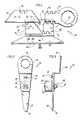
- FIGS. 5 and 6 show a cranked embodiment of the cutting knife 20, in which the holding part 24 is divided into two areas by the cranking, one area of which has the bore 25, preferably in the form of a polygon, while the other guide - And securing elements for attaching the blade part 22 to the holding part 24.
- a hook 42 punched out of the holding part 24 and which engages in a corresponding opening 43 in the blade part 22 is provided as the guide part.
- the blade part 22 is secured to the holding part 24 by a bolt 45, which carries at one end a support roller 46, the diameter of which is preferably selected so that the support roller extends circumferentially beyond the lateral edges of the blade part 22 and the holding part 24 .
- the bolt 45 With its other end, the bolt 45 is inserted into corresponding, aligned bores of the blade part 22 and of the holding part 24, the part of the bolt 45 projecting from this having an annular groove 47 at its end. A clamping disk 48 is then pressed over this free end of the bolt 45, the resilient elements of which snap into the annular groove 47.
- FIGS. 7 and 8 A flat, not cranked cutting knife 20 is shown in FIGS. 7 and 8, in which the holding part 24 carries two hook parts 42, which in this case consist of pins bearing flat, round heads.
- the blade part 22 has two elongated holes, each of which has a circular extension at one end through which the hook parts 42 can be inserted.
- the blade part 22 is fixed at a distance from the holding part 24, while displacement of the two parts relative to one another in the longitudinal direction of the knife is prevented by a securing clip 50 which engages around the holding part 24 and the blade part 22 and via one Hook part 42 is held in position with respect to the longitudinal direction of the cutting knife 20.
- FIGS. 9 and 10 A further variant of the cutting knife 20 is shown in FIGS. 9 and 10, the blade part 22 being subdivided into three areas, namely an actual blade 52, a guide 53 and an end area 54.
- the guide 53 of the blade part 22 in this case comprises bent-up side areas 56, which include the holding part 24 in the edge region.
- the shear forces occurring between the holding part 24 and the blade part 22 during the pivoting-oscillating movement of the cutting knife 20 are mainly absorbed by a pin 58 inserted into the holding part 24, which engages in a bore 59 in the blade part 22.
- the end region 54 of the blade part 22 has a polygonal bore 25 into which the drive shaft of the cutting tool engages.
- the corresponding end region of the holding part 24, which overlaps this end region 54 of the blade part 22, can likewise have a polygonal bore or can also be provided with a round bore in which a corresponding end of the drive shaft is guided.
- a corresponding guidance of blade part 22 and holding part 24 is shown in FIGS. 13 and 14, where side areas 61 grip around the blade part 22 and hold it flat on the holding part 24.
- a securing of the holding part 24 with respect to the blade part 22 is achieved when the cutting knife is mounted on the drive shaft, for example in the example shown in FIG. 13 that both the blade part and the holding part have aligned polygonal bores, in the drive shaft of the cutting tool is inserted.
- Figures 13 and 14 also show a variant with a U-shaped bent blade 52, which is preferred in certain applications.
- the guidance of the blade part on the holding part 24 is achieved via a hook 62 which is punched out of the blade part 22 and engages in an opening 63 of the holding part 24.
- Holding part 24 and blade part 22 are both bent in this embodiment, and run essentially parallel to one another.
- the cranked areas 65, 66 of the blade part 22 and the holding part 24 serve here in addition to the hook 62 to fix the blade part in relation to the holding part by means of a form-fitting contact.
- the bores of the blade part and the holding part, which receive the drive shaft of the cutting tool, are in turn designed as a polygon and at the same time serve as means for securing the two cutting knife parts to one another in the assembled state on the cutting tool.
- the holding part 24 is provided with a support roller 46 which is rotatably arranged in an end region facing the blade part 22.
- FIGS. 15 to 18 finally show still further exemplary embodiments of the cutting knives according to the invention, in which standard carpet knives can be used as blade parts 22.
- this cutting knife 20 corresponds in principle to that shown in FIG. 1.
- the carpet knife or blade part 22 is held on the holding part 24 via pins 26.
- the holding part 24 has the same width as the blade part 22 in the area overlapping with the blade part 22.
- a securing bracket 28 extends over the holding part 24 and the blade part 22 in this overlapping area and prevents the blade part from coming loose from the pins 26.
- the bracket 28 shown in FIGS. 15 and 16 has an eccentric lever 68 which in the position shown continuously in FIG. 16 with its cam 70 holds the holding part 24 and presses the blade 22 against it against the lugs 30 of the securing bracket 28.
- the lever arm 72 of the eccentric lever 68 lies essentially flat on the securing bracket 28.
- bracket 28 In the dash-dotted position shown in FIG. 16, the bracket 28 can be pulled off the holding part 24 and blade part 22, so that the carpet knife can be turned or exchanged.
- FIGS. 17 and 18 differs from the one described above in the manner in which the securing bracket 28 is fixed.
- a shoulder 74 is formed on the upper side of the bracket 28, into which an internal thread 75 is incorporated.
- the shoulder 74 with the internal thread receives a wing screw 76 which, in the tightened state (FIG. 18), as before, the eccentric lever 68 presses the holding part 24 against the adjacent blade part 22 and the lugs 30 of the bracket 28.
- the wing screw 76 only needs to be loosened so that the bracket 28 can be removed from the holding part 24 and the blade part 22.
- the knife shapes shown in the figures are of course only exemplary and can also be designed differently depending on the application, for example in certain cases a sickle-shaped appearance of the knives is preferred.
- the holding part and / or blade part can also be bent in the most varied of embodiments and not only in the illustrated.
- the attachment of a support roller is possible in all the embodiments shown and not only in the one shown in FIGS. 5 and 6.
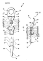
- a tenth exemplary embodiment of a cutting knife according to the invention designated as a whole by 20, shown in FIGS. 19 and 20, includes, like the previous exemplary embodiments, a blade part 22 and a holding part 24, the blade part 22 being interchangeably connectable to the holding part 24.
- the blade part 22 is provided with a cutting part 80 which extends in the longitudinal direction 82 of the blade part 22 starting from a fixing part 84 which is integrally connected to it and also aligned with it.
- the cutting part 80 is designed to taper to a tip 86 and is optionally provided with a cutting edge 88 either on one side or on both sides.
- the fixing part 84 which adjoins the cutting part 80 in one piece opposite the tip 86 is made from flat material of the same thickness as the cutting part 80 and has the shape of a flat cuboid with longitudinal side surfaces 90 parallel to the longitudinal direction 82 and also to one another.
- the fixing part is also provided with circular recesses 92 and 94 arranged centrally between the longitudinal side surfaces and one behind the other in the longitudinal direction 82.
- the holding part 24 comprises a base part 96 and a support part 98 which can be connected to the base part 96.
- the base part 96 has a fastening leg 100 which comprises the polygonal bore 25 for fastening the cutting knife 20 to the drive shaft of an oscillating oscillation drive. Starting from the fastening leg 100, the base part 96 is bent twice in opposite directions, so that it has an intermediate leg 102 bent relative to the fastening leg 100 and a holding leg 104 bent relative to the intermediate leg at an angle of approximately 90 °.
- the support part 98 can be placed on the base part 96 such that it essentially engages over the holding leg 104.
- the holding leg 104 is formed in a central region 106 adjoining the intermediate leg 102 in such a way that it has conical side surfaces 108 which converge towards one another and away from the intermediate leg 102 form-locking surfaces 110 which run parallel to one another and laterally delimit an end region 112 of the holding leg 104.
- the entire base part 96 is preferably formed in one piece from flat material, so that the form-fitting surfaces 108 and 110 of the holding leg are formed by the narrow side edges of the flat material.
- the support part 98 comprises a base plate 114, which is also made of flat material and whose shape corresponds essentially to the shape of the holding leg 104, with the difference that the front holding tabs 116 and rear holding tabs 118 projecting laterally perpendicular to the plane thereof are integrally formed thereon. Due to the essentially identical shape of the base plate 114 with the holding leg 104, the front holding lugs 116 run parallel to one another and the rear holding lugs 118 taper towards one another in the direction of the front holding lugs 116.
- the front holding lugs 116 thus form, on their mutually facing inner sides, front interlocking surfaces 120, which are intended to engage positively with the interlocking surfaces 110 of the holding leg 104, and the rear holding lugs 118 form, on their mutually facing inner surfaces, rear interlocking surfaces 122, which are provided for this purpose. to put on the form-fitting surfaces 108 of the holding leg 104, so that there is a total of a non-rotatable form-fitting between the support part 98 and the base part 96 in the assembled state.
- the support part 98 additionally has claws 126 on its rear side 124, which runs approximately parallel to the intermediate leg 102 in the assembled state of the holding part 24, and which have their outer ends 128 on a side facing the stop part Rounding surface 130 of the base part 96 at the transition from the holding leg 104 to the intermediate leg 102 when the support part 98 is placed in the mounting direction 132 are able to slide and are therefore endeavored to move the support part 98 in the direction of the intermediate leg 102 so that the form-fitting surfaces 122 and 108 widening in this direction come into contact with one another without play.
- the claws 126 are provided with little elasticity, so that after sliding on the rounded surface 130 they are always able to hold the support part 98 in this play-free position.
- the support part 98 overlapping the holding leg 104 forms together with this a receptacle for the fixing part 84 of the blade part 22, the fixing part 84 coming to lie between the support part 98 and the holding leg 104.
- the form-fitting receptacle is once formed by the front holding tabs 116, which, with their regions of the front form-fitting surfaces 120 rising directly above the base plate 114, form stop surfaces which cooperate with the longitudinal side surfaces 90 of the fixing part.
- the claws 126 are arranged at such a distance from one another that their mutually facing inner surfaces form further stop surfaces 134, between which the longitudinal side surfaces 90 of the fixing part 84 lie in the assembled state.
- this is provided with an annular bead 136 rising from the base plate 114, the outer surface of which fits into the recess 92 or 94.
- the fixing part 84 is always fixed by the annular bead 136, regardless of whether this engages in the recess 92 or the recess 94, in the support part in the longitudinal direction 82 in such a way that the longitudinal side surfaces 90 between both the front form-locking surfaces 120 and the stop surfaces 134 fit the claws 126.
- the blade part 22 with the fixing part 84 is now placed in the support part 98 so that the annular bead 136 engages either the recess 92 or the recess 94 and then the base part 96 is placed so that the holding leg 104 the fixing part 84 against the Base plate 114 of the support member 98 presses.
- a screw 138 is provided which passes through the holding leg 104 in a bore 140 and with its thread into an inside of the Ring bead 136 cut internal thread 142 can be screwed.
- the height at which the annular bead 136 rises from the base plate 114 is to be dimensioned such that it does not protrude beyond the fixing part 84 in the direction of the holding leg 104 when it is in place.
- the support part 98 is preferably placed on the side of the holding leg 104 which is opposite to the direction in which the intermediate leg 102 rises from the holding leg 104.
- a support roller 144 is provided in the end region 112 of the holding leg 104, which protrudes beyond a front edge 146 of the end region 112 facing the tip 86 of the blade part 22 and is rotatably mounted on a pin 148, which rises from the holding leg 104 in the same direction as the intermediate leg 102.
- the arrangement of the support roller 144 and the screw 138 with their head 150 on the side on which the intermediate leg 102 also rises from the holding leg 104 ensures that the cutting knife 20 according to the invention can be used without striking the motor vehicle body in a disturbing manner .
Landscapes
- Engineering & Computer Science (AREA)
- Mechanical Engineering (AREA)
- Life Sciences & Earth Sciences (AREA)
- Forests & Forestry (AREA)
- Architecture (AREA)
- Civil Engineering (AREA)
- Structural Engineering (AREA)
- Knives (AREA)
- Control And Other Processes For Unpacking Of Materials (AREA)
- Perforating, Stamping-Out Or Severing By Means Other Than Cutting (AREA)
- Auxiliary Devices For Machine Tools (AREA)
Priority Applications (1)
| Application Number | Priority Date | Filing Date | Title |
|---|---|---|---|
| AT89106386T ATE90904T1 (de) | 1988-04-29 | 1989-04-11 | Schneidmesser. |
Applications Claiming Priority (2)
| Application Number | Priority Date | Filing Date | Title |
|---|---|---|---|
| DE3814554A DE3814554A1 (de) | 1988-04-29 | 1988-04-29 | Schneidmesser |
| DE3814554 | 1988-04-29 |
Publications (3)
| Publication Number | Publication Date |
|---|---|
| EP0339357A2 true EP0339357A2 (fr) | 1989-11-02 |
| EP0339357A3 EP0339357A3 (en) | 1990-08-22 |
| EP0339357B1 EP0339357B1 (fr) | 1993-06-23 |
Family
ID=6353216
Family Applications (1)
| Application Number | Title | Priority Date | Filing Date |
|---|---|---|---|
| EP89106386A Expired - Lifetime EP0339357B1 (fr) | 1988-04-29 | 1989-04-11 | Outil de coupe |
Country Status (7)
| Country | Link |
|---|---|
| US (1) | US4989320A (fr) |
| EP (1) | EP0339357B1 (fr) |
| JP (1) | JPH0669511B2 (fr) |
| KR (1) | KR960013242B1 (fr) |
| AT (1) | ATE90904T1 (fr) |
| DE (2) | DE3814554A1 (fr) |
| ES (1) | ES2045231T3 (fr) |
Cited By (3)
| Publication number | Priority date | Publication date | Assignee | Title |
|---|---|---|---|---|
| EP0711636A1 (fr) * | 1994-11-08 | 1996-05-15 | Engelbert Gmeilbauer | Outil motorisé vibrant portable |
| EP0722802A1 (fr) * | 1995-01-20 | 1996-07-24 | Metabowerke GmbH & Co. | Dispositif pour recevoir une lame de scie abloquable par une seule extrémité |
| EP1208950A1 (fr) * | 2000-11-23 | 2002-05-29 | C. & E. Fein Gmbh & Co. KG | Outil avec support pour la fixation à un arbre d'entrainement |
Families Citing this family (37)
| Publication number | Priority date | Publication date | Assignee | Title |
|---|---|---|---|---|
| DE3929852A1 (de) * | 1989-08-15 | 1991-02-21 | Fein C & E | Schaelmesser |
| DE4135573A1 (de) * | 1990-11-28 | 1992-06-04 | Fein C & E | Verfahren und vorrichtung zum einbringen von oberflaechenkanaelen in plattenmaterial aus weichem werkstoff und verwendung einer vorrichtung |
| DE4127239C1 (fr) * | 1991-08-17 | 1992-12-24 | C. & E. Fein Gmbh & Co, 7000 Stuttgart, De | |
| DE9417859U1 (de) * | 1994-11-08 | 1995-03-02 | Gmeilbauer, Engelbert, 82229 Seefeld | Zusatzhalterung für Maschinen mit Oszillationsantrieb |
| DE4440747A1 (de) * | 1994-11-15 | 1996-05-30 | Hoffmann Hans Guenter | Vorrichtung zum Erneuern von Dichtnähten, insbesondere im Kfz- und Bauhandwerk |
| US5826342A (en) * | 1996-08-05 | 1998-10-27 | Equalizer Industries, Inc. | Vehicle windshield removing tool |
| DE20305402U1 (de) * | 2003-03-31 | 2003-05-28 | C. & E. Fein GmbH & Co KG, 70176 Stuttgart | Schleifwerkzeug zum Schärfen von Werkzeugen |
| US20050252010A1 (en) * | 2004-05-17 | 2005-11-17 | Fiskars Brands, Inc. | Exchangeable blade knife |
| USD581241S1 (en) | 2004-05-17 | 2008-11-25 | Fiskars Brands, Inc. | Knife handle |
| DE102004050635A1 (de) * | 2004-10-18 | 2006-04-20 | C. & E. Fein Gmbh | Hartschaum-Trägerplatte zur Aufnahme der Heizrohre einer Fußbodenheizung sowie Werkzeug zum Einarbeiten des Verlegekanals und Verfahren zum Verlegen von Heizrohren in der Hartschaum-Trägerplatte |
| US7805843B2 (en) * | 2006-09-15 | 2010-10-05 | Bel-Art Products, Inc. | Eating utensil |
| US20060288829A1 (en) * | 2006-09-19 | 2006-12-28 | Robert Sipperly | Hardened Utility Knife, With Optional Nail Set and Pry Bar |
| US8413338B2 (en) * | 2009-07-14 | 2013-04-09 | Fiskars Brands, Inc. | Folding knife with safety and wedge lock |
| USD614933S1 (en) | 2009-10-02 | 2010-05-04 | Fiskars Brands, Inc. | Knife handle |
| USD639632S1 (en) | 2009-10-02 | 2011-06-14 | Fiskars Brands, Inc. | Knife handle |
| USD623034S1 (en) | 2009-12-18 | 2010-09-07 | Techtronic Power Tools Technology Limited | Tool arbor |
| USD619152S1 (en) | 2009-12-18 | 2010-07-06 | Techtronic Power Tools Technology Limited | Adapter |
| EP2388107B1 (fr) | 2009-12-18 | 2019-09-04 | Techtronic Power Tools Technology Limited | Système d'outil multifonction |
| USD636052S1 (en) | 2010-08-31 | 2011-04-12 | Fiskars Brands, Inc. | Knife handle |
| USD636053S1 (en) | 2010-08-31 | 2011-04-12 | Fiskars Brands, Inc. | Knife handle |
| USD636051S1 (en) | 2010-08-31 | 2011-04-12 | Fiskars Brands, Inc. | Knife handle |
| USD638904S1 (en) | 2010-08-31 | 2011-05-31 | Fiskars Brands, Inc. | Knife handle |
| USD646542S1 (en) | 2010-09-29 | 2011-10-11 | Milwaukee Electric Tool Corporation | Accessory interface for a tool |
| USD653523S1 (en) | 2010-09-29 | 2012-02-07 | Milwaukee Electric Tool Corporation | Adapter for a tool |
| USD651062S1 (en) | 2010-09-29 | 2011-12-27 | Milwaukee Electric Tool Corporation | Tool interface for an accessory |
| USD661367S1 (en) | 2011-05-12 | 2012-06-05 | Fiskars Brands, Inc. | Knife handle |
| US8893389B2 (en) | 2011-05-31 | 2014-11-25 | Fiskars Brands, Inc. | Cantilever spring assist knife |
| US10532472B2 (en) * | 2012-01-04 | 2020-01-14 | Robert Bosch Tool Corporation | Hook blade accessory tool for an oscillating tool |
| DE102012007489A1 (de) * | 2012-03-30 | 2013-10-02 | C. & E. Fein Gmbh | Spachtel |
| US9555554B2 (en) | 2013-05-06 | 2017-01-31 | Milwaukee Electric Tool Corporation | Oscillating multi-tool system |
| US9527146B2 (en) | 2013-10-04 | 2016-12-27 | Toronto Saw Works Inc. | Oscillating saw blades |
| US10456945B2 (en) * | 2014-12-29 | 2019-10-29 | Robert Bosch Tool Corporation | Tool for manually operating oscillating motorized tool accessory |
| US10016904B2 (en) * | 2015-02-03 | 2018-07-10 | Ralph Scott Jones | Guide blades for oscillating and reciprocating power tools |
| WO2016132320A1 (fr) * | 2015-02-19 | 2016-08-25 | Toronto Saw Works Inc. | Lames de scie avec des joints non-linéaire |
| US11097434B2 (en) | 2017-12-21 | 2021-08-24 | Mark Gordon Hooper | Utility knife |
| US10906108B2 (en) * | 2018-04-24 | 2021-02-02 | Robert Bosch Tool Corporation | Blade accessory with guide |
| USD895384S1 (en) * | 2019-02-19 | 2020-09-08 | Slice, Inc. | Blade |
Family Cites Families (24)
| Publication number | Priority date | Publication date | Assignee | Title |
|---|---|---|---|---|
| US1779474A (en) * | 1929-02-23 | 1930-10-28 | Jackson Corwill | Tamper |
| US2681502A (en) * | 1953-10-09 | 1954-06-22 | Orman L Black | Safety box opener |
| US2912843A (en) * | 1959-04-17 | 1959-11-17 | Lonnie M Gary | Skiving tool |
| US3488843A (en) * | 1967-11-15 | 1970-01-13 | Camson Mfg Co | Hand cutting tool with means to support a plurality of blades and means to hold a single blade in a cutting position |
| US3791014A (en) * | 1972-05-22 | 1974-02-12 | A Perna | Hand cutting tool for gypsum plaster boards or the like |
| GB1446204A (en) * | 1973-03-05 | 1976-08-18 | Jacobs Mfg Co | Fitment of handles to bladed hand tools |
| US3965575A (en) * | 1974-08-19 | 1976-06-29 | Bigelow-Sanford, Inc. | Knife blade support unit |
| US3924327A (en) * | 1974-09-25 | 1975-12-09 | Jerry Clyde Edwards | Powered windshield track cutter |
| DE7623976U1 (de) * | 1976-07-30 | 1976-12-02 | Gojek, Friedrich, 6551 Winterburg | Brotkrusten-abschneidmesser |
| US4080734A (en) * | 1976-09-24 | 1978-03-28 | Barbour Deryle R | Method and apparatus for removing a vehicle windshield |
| SE402415B (sv) * | 1977-04-25 | 1978-07-03 | Farden Arne Sigvard Brynolf | Berbar anordning med avskalningsdon, som er forsett med ett skivformigt skerstalblad |
| US4109380A (en) * | 1977-07-05 | 1978-08-29 | Anderson Lloyd E | Cutting tool and blade holder for replaceable blades |
| US4215475A (en) * | 1978-06-12 | 1980-08-05 | Gould Kenneth D | Oscillating cut-out tool |
| US4199852A (en) * | 1978-11-22 | 1980-04-29 | Ayers Lewis W | Windshield remover |
| JPS5624038U (fr) * | 1979-07-31 | 1981-03-04 | ||
| JPS57196468U (fr) * | 1981-06-10 | 1982-12-13 | ||
| EP0081199A3 (fr) * | 1981-12-09 | 1984-11-28 | Hermann Hänssler | Couteau pour couper des coutures emmêlées |
| DE3210212A1 (de) * | 1982-03-19 | 1983-05-19 | Daimler-Benz Ag, 7000 Stuttgart | Schneidwerkzeug zum ausbau von eingeklebten fensterscheiben |
| DE3324676C1 (de) * | 1983-02-12 | 1984-10-11 | Daimler-Benz Ag, 7000 Stuttgart | Schneidwerkzeug zum Ausbau von eingeklebten Fensterscheiben |
| DE8325025U1 (de) * | 1983-08-31 | 1983-12-22 | C. & E. Fein Gmbh & Co, 7000 Stuttgart | Schneidwerkzeug |
| DE8423004U1 (de) * | 1984-08-02 | 1984-10-31 | C. & E. Fein Gmbh & Co, 7000 Stuttgart | Schneidmesser zum durchtrennen der klebeschicht einer angeklebten scheibe |
| US4748743A (en) * | 1987-01-12 | 1988-06-07 | Anderson Lloyd E | Utility knife with improved blade locking feature |
| DE3712707A1 (de) * | 1987-04-14 | 1988-11-03 | Chicago Pneumatic Zweigniederl | Messereinsatz |
| US4788770A (en) * | 1987-06-19 | 1988-12-06 | Rodrigue Simard | Scraper for scratch coupons |
-
1988
- 1988-04-29 DE DE3814554A patent/DE3814554A1/de not_active Withdrawn
-
1989
- 1989-04-11 ES ES89106386T patent/ES2045231T3/es not_active Expired - Lifetime
- 1989-04-11 EP EP89106386A patent/EP0339357B1/fr not_active Expired - Lifetime
- 1989-04-11 DE DE8989106386T patent/DE58904769D1/de not_active Expired - Fee Related
- 1989-04-11 AT AT89106386T patent/ATE90904T1/de not_active IP Right Cessation
- 1989-04-21 US US07/341,369 patent/US4989320A/en not_active Expired - Fee Related
- 1989-04-28 JP JP1107937A patent/JPH0669511B2/ja not_active Expired - Lifetime
- 1989-04-29 KR KR1019890005861A patent/KR960013242B1/ko not_active Expired - Fee Related
Cited By (3)
| Publication number | Priority date | Publication date | Assignee | Title |
|---|---|---|---|---|
| EP0711636A1 (fr) * | 1994-11-08 | 1996-05-15 | Engelbert Gmeilbauer | Outil motorisé vibrant portable |
| EP0722802A1 (fr) * | 1995-01-20 | 1996-07-24 | Metabowerke GmbH & Co. | Dispositif pour recevoir une lame de scie abloquable par une seule extrémité |
| EP1208950A1 (fr) * | 2000-11-23 | 2002-05-29 | C. & E. Fein Gmbh & Co. KG | Outil avec support pour la fixation à un arbre d'entrainement |
Also Published As
| Publication number | Publication date |
|---|---|
| DE58904769D1 (de) | 1993-07-29 |
| JPH0669511B2 (ja) | 1994-09-07 |
| DE3814554A1 (de) | 1989-11-09 |
| KR960013242B1 (ko) | 1996-10-02 |
| ES2045231T3 (es) | 1994-01-16 |
| US4989320A (en) | 1991-02-05 |
| JPH01314585A (ja) | 1989-12-19 |
| KR890015825A (ko) | 1989-11-25 |
| ATE90904T1 (de) | 1993-07-15 |
| EP0339357B1 (fr) | 1993-06-23 |
| EP0339357A3 (en) | 1990-08-22 |
Similar Documents
| Publication | Publication Date | Title |
|---|---|---|
| EP0339357B1 (fr) | Outil de coupe | |
| DE19543247B4 (de) | Werkzeug mit hin- und hergehender Arbeitsbewegung | |
| AT394082B (de) | Moebelscharnier | |
| EP1213107B2 (fr) | Montage pour fixer un outil à un arbre d'entraînement et adapteur pour celui-ci | |
| EP1879721B1 (fr) | Pince | |
| DE4127239C1 (fr) | ||
| EP1208950B1 (fr) | Outil avec support pour la fixation à un arbre d'entrainement | |
| DE2624370A1 (de) | Vorrichtung zum lokalisieren eines fuehrungsbohrers fuer eine lochsaege | |
| EP0196437A2 (fr) | Couteau pour pose, en particulier couteau à tailler des tapis | |
| DE2952918C1 (de) | Messerkopf fuer ein elektrisches Haarschneidegeraet | |
| DE69201561T2 (de) | Schere. | |
| DE29916682U1 (de) | Anordnung zur Sicherung eines Bauteils | |
| EP3272207B1 (fr) | Appareil de travail comprenant des boîtiers partiels reliés par une articulation pivotante | |
| DE20309329U1 (de) | Befestigungsvorrichtung für Werkzeug | |
| DE2433358C2 (de) | Dentaltechnisches Geschiebe zur lösbaren Befestigung von Zahnprothesen am Restgebiß | |
| DE2700465A1 (de) | Gewindeschneidkluppe | |
| DE19938512A1 (de) | Miniatur-Entgratwerkzeug | |
| DE10160729B4 (de) | Befestigungsanker mit Schraubenmutter | |
| DE3628911C2 (fr) | ||
| EP0204023B1 (fr) | Guidage longitudinal, spécialement pour une scie circulaire | |
| DE2435359A1 (de) | Tuerdrueckerverbindung | |
| DE2343507B2 (de) | Scharniergelenk für Fenster, Türen o.dgl | |
| DE8814964U1 (de) | Bausatz für eine Türzarge | |
| DE20122817U1 (de) | Aufnahme zur Befestigung eines Werkzeuges an einer Antriebswelle und Adapter hierzu | |
| DE20321677U1 (de) | Vorrichtung zum Fixieren eines Knochendeckels am Schädel |
Legal Events
| Date | Code | Title | Description |
|---|---|---|---|
| PUAI | Public reference made under article 153(3) epc to a published international application that has entered the european phase |
Free format text: ORIGINAL CODE: 0009012 |
|
| AK | Designated contracting states |
Kind code of ref document: A2 Designated state(s): AT BE CH DE ES FR GB IT LI NL SE |
|
| PUAL | Search report despatched |
Free format text: ORIGINAL CODE: 0009013 |
|
| AK | Designated contracting states |
Kind code of ref document: A3 Designated state(s): AT BE CH DE ES FR GB IT LI NL SE |
|
| 17P | Request for examination filed |
Effective date: 19901113 |
|
| 17Q | First examination report despatched |
Effective date: 19920207 |
|
| GRAA | (expected) grant |
Free format text: ORIGINAL CODE: 0009210 |
|
| AK | Designated contracting states |
Kind code of ref document: B1 Designated state(s): AT BE CH DE ES FR GB IT LI NL SE |
|
| REF | Corresponds to: |
Ref document number: 90904 Country of ref document: AT Date of ref document: 19930715 Kind code of ref document: T |
|
| GBT | Gb: translation of ep patent filed (gb section 77(6)(a)/1977) |
Effective date: 19930630 |
|
| REF | Corresponds to: |
Ref document number: 58904769 Country of ref document: DE Date of ref document: 19930729 |
|
| ET | Fr: translation filed | ||
| ITF | It: translation for a ep patent filed | ||
| REG | Reference to a national code |
Ref country code: ES Ref legal event code: FG2A Ref document number: 2045231 Country of ref document: ES Kind code of ref document: T3 |
|
| PLBE | No opposition filed within time limit |
Free format text: ORIGINAL CODE: 0009261 |
|
| STAA | Information on the status of an ep patent application or granted ep patent |
Free format text: STATUS: NO OPPOSITION FILED WITHIN TIME LIMIT |
|
| 26N | No opposition filed | ||
| EAL | Se: european patent in force in sweden |
Ref document number: 89106386.9 |
|
| PGFP | Annual fee paid to national office [announced via postgrant information from national office to epo] |
Ref country code: GB Payment date: 19990315 Year of fee payment: 11 |
|
| PGFP | Annual fee paid to national office [announced via postgrant information from national office to epo] |
Ref country code: AT Payment date: 19990324 Year of fee payment: 11 |
|
| PGFP | Annual fee paid to national office [announced via postgrant information from national office to epo] |
Ref country code: SE Payment date: 19990325 Year of fee payment: 11 |
|
| PGFP | Annual fee paid to national office [announced via postgrant information from national office to epo] |
Ref country code: CH Payment date: 19990326 Year of fee payment: 11 |
|
| PGFP | Annual fee paid to national office [announced via postgrant information from national office to epo] |
Ref country code: NL Payment date: 19990329 Year of fee payment: 11 |
|
| PGFP | Annual fee paid to national office [announced via postgrant information from national office to epo] |
Ref country code: BE Payment date: 19990414 Year of fee payment: 11 |
|
| PGFP | Annual fee paid to national office [announced via postgrant information from national office to epo] |
Ref country code: ES Payment date: 19990420 Year of fee payment: 11 |
|
| PG25 | Lapsed in a contracting state [announced via postgrant information from national office to epo] |
Ref country code: GB Free format text: LAPSE BECAUSE OF NON-PAYMENT OF DUE FEES Effective date: 20000411 Ref country code: AT Free format text: LAPSE BECAUSE OF NON-PAYMENT OF DUE FEES Effective date: 20000411 |
|
| PG25 | Lapsed in a contracting state [announced via postgrant information from national office to epo] |
Ref country code: SE Free format text: LAPSE BECAUSE OF NON-PAYMENT OF DUE FEES Effective date: 20000412 Ref country code: ES Free format text: THE PATENT HAS BEEN ANNULLED BY A DECISION OF A NATIONAL AUTHORITY Effective date: 20000412 |
|
| PG25 | Lapsed in a contracting state [announced via postgrant information from national office to epo] |
Ref country code: LI Free format text: LAPSE BECAUSE OF NON-PAYMENT OF DUE FEES Effective date: 20000430 Ref country code: CH Free format text: LAPSE BECAUSE OF NON-PAYMENT OF DUE FEES Effective date: 20000430 Ref country code: BE Free format text: LAPSE BECAUSE OF NON-PAYMENT OF DUE FEES Effective date: 20000430 |
|
| BERE | Be: lapsed |
Owner name: C. & E. FEIN G.M.B.H. & CO. Effective date: 20000430 |
|
| PG25 | Lapsed in a contracting state [announced via postgrant information from national office to epo] |
Ref country code: NL Free format text: LAPSE BECAUSE OF NON-PAYMENT OF DUE FEES Effective date: 20001101 |
|
| GBPC | Gb: european patent ceased through non-payment of renewal fee |
Effective date: 20000411 |
|
| EUG | Se: european patent has lapsed |
Ref document number: 89106386.9 |
|
| REG | Reference to a national code |
Ref country code: CH Ref legal event code: PL |
|
| NLV4 | Nl: lapsed or anulled due to non-payment of the annual fee |
Effective date: 20001101 |
|
| PGFP | Annual fee paid to national office [announced via postgrant information from national office to epo] |
Ref country code: FR Payment date: 20020128 Year of fee payment: 14 |
|
| REG | Reference to a national code |
Ref country code: ES Ref legal event code: FD2A Effective date: 20020204 |
|
| PG25 | Lapsed in a contracting state [announced via postgrant information from national office to epo] |
Ref country code: FR Free format text: LAPSE BECAUSE OF NON-PAYMENT OF DUE FEES Effective date: 20031231 |
|
| REG | Reference to a national code |
Ref country code: FR Ref legal event code: ST |
|
| PGFP | Annual fee paid to national office [announced via postgrant information from national office to epo] |
Ref country code: DE Payment date: 20050407 Year of fee payment: 17 |
|
| PG25 | Lapsed in a contracting state [announced via postgrant information from national office to epo] |
Ref country code: IT Free format text: LAPSE BECAUSE OF NON-PAYMENT OF DUE FEES;WARNING: LAPSES OF ITALIAN PATENTS WITH EFFECTIVE DATE BEFORE 2007 MAY HAVE OCCURRED AT ANY TIME BEFORE 2007. THE CORRECT EFFECTIVE DATE MAY BE DIFFERENT FROM THE ONE RECORDED. Effective date: 20050411 |
|
| PG25 | Lapsed in a contracting state [announced via postgrant information from national office to epo] |
Ref country code: DE Free format text: LAPSE BECAUSE OF NON-PAYMENT OF DUE FEES Effective date: 20061101 |