EP0339425A2 - Système haut-parleur - Google Patents
Système haut-parleur Download PDFInfo
- Publication number
- EP0339425A2 EP0339425A2 EP89106833A EP89106833A EP0339425A2 EP 0339425 A2 EP0339425 A2 EP 0339425A2 EP 89106833 A EP89106833 A EP 89106833A EP 89106833 A EP89106833 A EP 89106833A EP 0339425 A2 EP0339425 A2 EP 0339425A2
- Authority
- EP
- European Patent Office
- Prior art keywords
- sound
- speaker system
- acoustic path
- diaphragm
- absorbing member
- Prior art date
- Legal status (The legal status is an assumption and is not a legal conclusion. Google has not performed a legal analysis and makes no representation as to the accuracy of the status listed.)
- Granted
Links
Images


Classifications
-
- H—ELECTRICITY
- H04—ELECTRIC COMMUNICATION TECHNIQUE
- H04R—LOUDSPEAKERS, MICROPHONES, GRAMOPHONE PICK-UPS OR LIKE ACOUSTIC ELECTROMECHANICAL TRANSDUCERS; ELECTRIC HEARING AIDS; PUBLIC ADDRESS SYSTEMS
- H04R1/00—Details of transducers, loudspeakers or microphones
- H04R1/20—Arrangements for obtaining desired frequency or directional characteristics
- H04R1/22—Arrangements for obtaining desired frequency or directional characteristics for obtaining desired frequency characteristic only
- H04R1/30—Combinations of transducers with horns, e.g. with mechanical matching means, i.e. front-loaded horns
-
- H—ELECTRICITY
- H04—ELECTRIC COMMUNICATION TECHNIQUE
- H04R—LOUDSPEAKERS, MICROPHONES, GRAMOPHONE PICK-UPS OR LIKE ACOUSTIC ELECTROMECHANICAL TRANSDUCERS; ELECTRIC HEARING AIDS; PUBLIC ADDRESS SYSTEMS
- H04R1/00—Details of transducers, loudspeakers or microphones
- H04R1/20—Arrangements for obtaining desired frequency or directional characteristics
- H04R1/32—Arrangements for obtaining desired frequency or directional characteristics for obtaining desired directional characteristic only
- H04R1/34—Arrangements for obtaining desired frequency or directional characteristics for obtaining desired directional characteristic only by using a single transducer with sound reflecting, diffracting, directing or guiding means
- H04R1/345—Arrangements for obtaining desired frequency or directional characteristics for obtaining desired directional characteristic only by using a single transducer with sound reflecting, diffracting, directing or guiding means for loudspeakers
Definitions
- the present invention relates to a speaker system having a horn or an acoustic pipe provided in front of the speaker diaphragm and adapted for guiding sonic waves therefrom.
- a speaker system in which a sound wave generated by a diaphragm is introduced to the second outlet opening of the speaker through a horn or an acoustic pipe provided on the front side of the diaphragm.
- This type of speaker systems is finding increasingly wide use because it provides a higher level of the output sound pressure and superior directivity as compared with ordinary speaker systems which do not have such a horn or acoustic pipe.
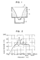
- a back cavity 2 is provided on the rear side of a speaker unit 1 for the purpose of preventing radiation of reflected sound from the speaker diaphragm.
- a horn 9 is provided in front of the speaker diaphragm and extends towards the sound outlet opening of the speaker system. The cross-sectional area of the horn 9 is progressively increased from the end adjacent to the speaker diaphragm towards the end adjacent to the sound outlet opening of the speaker system. The horn 9 thus constitutes an acoustic path 5 which introduces the sound wave output from the speaker.
- the change in the acoustic impedance at the sound outlet opening of the speaker system is made extremely small provided that the horn 9 has a length which is sufficiently greater than the length of the wavelengths of sound wave of the reproduction band.
- a very good matching is obtained at the sound outlet opening of the speaker system so that a flat reproduction sound pressure frequency characteristic is obtained thus realizing an ideal speaker system.
- the speaker systems employing such horns usually exhibit a reproduction sound pressure frequency characteristic which contains many peaks and troughs as shown in Figs. 2B and 8B.
- an object of the present invention is to provide a speaker system which provides a flat sound pressure frequency characteristics free of resonance peaks and troughs without requiring the length of the horn or the acoustic pipe to be increased.
- a speaker system comprising: an acoustic path provided on the front side of a speaker diaphragm and adapted for introducing a sound wave, the acoustic path being defined by a sound absorbing member; and a partition member which is disposed in the acoustic path in such a manner that at least a portion of the sound absorbing material is exposed to the interior of the acoustic path.
- the sound wave components reflected due to a drastic change in the acoustic impedance at the sound outlet opening are effectively absorbed by the sound absorbing member constituting the sound path, thereby providing flat sound pressure frequency characteristics with reduced peaks and troughs.
- the components of the sound wave other than those which cause the peaks and troughs are introduced along the surface of the partition member to the sound outlet opening of the speaker system, without being absorbed by the sound absorbing member, whereby the reproduction band can be broadened.
- Japanese Patent Unexamined Publication No. 49-134312 discloses a speaker system in which a horn for guiding the sound wave from a diaphragm is made from a material which exhibits a small tendency of generation of reflected waves (noise), i.e., a material which absorbs the noise well. This, however, is irrelevant to the invention of this application which is intended for absorbing reflected waves attributable to a drastic change in the acoustic impedance at the sound outlet opening of the speaker system.
- a first embodiment of the speaker system of the present invention has a speaker unit 1 with a back cavity 2 on the rear side thereof, an acoustic pipe 3 for guiding and introducing sound waves generated on the front side of the diaphragm of the speaker unit 1, and a sound absorbing member 4 disposed in the acoustic pipe 3 and defining an acoustic path 5.
- this speaker system is as follows.
- the sound emitted from the rear side of the speaker unit 1 is confined in the back cavity 2 so that it is not transmitted to the outside of the speaker system.
- the sound emitted from the front side of the diaphragm is introduced through the acoustic pipe 3 to the sound outlet opening of the speaker system so as to be radiated therefrom.
- a part of the sound wave introduced to the sound outlet opening is reflected due to a drastic change in the acoustic impedance, tending to propagate backward to the diaphragm surface.
- the reflected sound wave is conveniently absorbed by the sound absorbing material disposed in the acoustic pipe, thus eliminating existence of a standing wave in the acoustic pipe.
- the sound absorbing member 4 has a smaller thickness in the region near the sound outlet opening and a greater thickness at the region adjacent to the speaker unit 1, so that the impedance of the sound absorbing member 4 to the reflected wave is reduced to ensure a high sound absorbing effect.
- the amount of the material of the sound absorbing member 4 is increased towards the front side of the diaphragm so that the impedance exhibited by the sound absorbing member 4 to the reflected sound wave is linearly changed, whereby the reflected sound wave from the sound outlet opening is effectively absorbed by the sound absorbing member without any unnecessary reflection.
- the linear and progressive change in the impedance provided by the sound absorbing member may be controlled in various ways. For instance, it is possible to control the manner of change in the impedance by suitably varying the amount of the material of the sound absorbing member 4 along the length thereof, or by adjusting the flow resistance per unit area such that it is small in the region near the sound outlet opening and large in the region near the surface of the diaphragm.
- the sound wave produced by the diaphragm can be introduced to the sound outlet opening through the acoustic path defined by the sound absorbing member 4 without being impeded by the sound absorbing member 4.
- Fig. 2 illustrates the reproduction sound pressure frequency characteristics exhibited by a speaker system with the horn or acoustic pipe in accordance with the first embodiment, in comparison with the characteristics exhibited by the conventional arrangement. From this Figure, it will be understood that the conventional speaker system exhibits characteristics B which includes peaks and troughs due to existence of a standing wave, while the speaker system of the first embodiment exhibits flat reproduction sound pressure frequency characteristics A up to high pitch region of the tone.
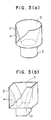
- the cross-sectional area of the acoustic path is increased from the end adjacent to the surface of the diaphragm towards the sound outlet opening.
- Such an acoustic path 5 may be defined solely by the sound absorbing member 4 as shown in Fig. 3(a) or, alternatively, the arrangement may be such that the sound absorbing member 4 and the wall of the acoustic pipe 3 in cooperation define the acoustic path 5, as shown in Fig. 3(b).
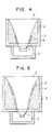
- Fig. 4 is a sectional view of a second embodiment of the speaker system in accordance with the present invention.
- the second embodiment of the speaker system has a speaker unit 1, a back cavity 2, an acoustic pipe for introducing acoustic waves generated on the front side of the diaphragm, a partition member 6 disposed in the acoustic pipe 3 so as to define an acoustic path 5, and a sound absorbing member 4 a part of which is disposed between the partition member 6 and the wall of the acoustic pipe 3 while the other part is exposed so as to define the acoustic path 5.
- the operation of the second embodiment is as follows.
- the sound wave emitted from the rear side of the diaphragm in the speaker unit 1 is confined in the back cavity 2 so that it does not radiate to the outside.
- the sound wave emitted from the front side of the diaphragm is guided by the acoustic pipe 3 to reach the sound outlet opening so as to be radiated therefrom.
- a drastic change in the acoustic impedance is generated in the sound outlet opening, a portion of the sound wave introduced to the opening is reflected so as to be propagated backward towards the front surface of the diaphragm.
- the reflected wave is absorbed by the sound absorbing member 4 disposed in the acoustic pipe 3, so that no standing wave exists in the acoustic pipe 3.
- the partition member 6 is so sized as to extend over about 1/3 of the acoustic pipe 3 as measured from the surface of the diaphragm, and is intended to effectively guide the high-pitch components of the sound which tend to be absorbed by the sound absorbing member 4.
- the portion of the acoustic pipe 3 which is about 1/3 the whole length of the acoustic pipe 3 as measured from the surface of the diaphragm substantially coincides with the region where the particle velocity is high. It is therefore possible to suppress the peaks of the sound pressure in the frequency region in which the standing wave is generated.
- the sound wave components of other frequencies are introduced efficiently to the sound outlet opening without being impeded by the sound absorbing member, because the sound absorbing member is designed in the form of a horn.
- the second embodiment can be carried out with various forms of the acoustic path 5 as illustrated in Figs. 3(a) to 3(c), without impairing the advantages derived therefrom.
- Fig. 5 shows a third embodiment of the speaker system of the present invention.
- the third embodiment has a speaker unit 1, a back cavity 2, an acoustic pipe 3 for guiding sound wave generated on the front side of the diaphragm in the speaker unit 1, a partition member 6 disposed in the acoustic pipe 3 so as to define an acoustic path 5 and having slits one of which is located near the sound outlet opening of the acoustic pipe 3 while the other is in the region which is about 1/3 of the full length of the acoustic pipe 3 as measured from the surface of the speaker diaphragm, and a sound absorbing material received in the space between the acoustic pipe 3 and the partition member 6.
- the operation of the speaker system in accordance with the third embodiment is as follows.
- the sound wave emitted from the rear side of the speaker unit 1 is confined in the back cavity 2 so that it does not radiate outside.
- the sound from the front side of the diaphragm in the speaker unit 1 is guided by the acoustic pipe 3 to reach the sound outlet opening so as to be radiated therefrom.
- a portion of the sound wave reaching the sound outlet opening is reflected because the acoustic impedance is drastically changed at the sound outlet opening.
- the reflected wave tends to propagate backward towards the surface of the diaphragm.
- the reflected wave is effectively absorbed by the sound absorbing member 4 in the acoustic pipe 3 so that no standing wave is generated in the acoustic pipe.
- the partition member 6 has slits in the region near the sound outlet opening and in the region which is 1/3 of the full length of the acoustic pipe 3 as measured from the surface of the speaker diaphragm, i.e., in the regions where the particle velocity is high. It is therefore possible to selectively absorb the sound wave components of frequency regions having peaks of sound pressure. Other components of the sound wave can be guided to the sound outlet opening without being impeded by the sound absorbing member 4.
- the third embodiment also provides flat sound pressure frequency characteristics, by suppressing the peaks of sound pressure which are inevitably high in the known horn or acoustic pipe due to the presence of a standing wave.
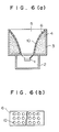
- Figs. 6(a) and 6(b) show a fourth embodiment of the speaker system in accordance with the present invention.
- the fourth embodiment has a speaker unit 1, a back cavity 2, an acoustic pipe 3 which guides the sound wave generated on the front side of the diaphragm of the speaker unit 1, a partition member 6 disposed in the acoustic pipe 3 so as to define an acoustic path 5 and having a plurality of apertures, and a sound absorbing member 4 filling the space between the wall of the acoustic pipe 3 and the partition member 6.
- the apertures 10 formed in the partition member 6 have a diameter of 8 mm and are arranged at a pitch of 30 mm.
- the operation of the fourth embodiment of the speaker system will be described hereinunder.
- the sound emitted from the rear side of the diaphragm of the speaker unit 1 is confined in the back cavity 2 so that it does not radiate to the outside.
- the sound wave emitted from the front side of the diaphragm is guided to the sound outlet opening through the acoustic pipe 3 so as to be radiated therefrom.
- a portion of the sound wave reaching the sound outlet opening of the acoustic pipe 3, however, is reflected to propagate backward towards the front surface of the diaphragm, because a drastic change in the acoustic impedance takes place at the sound outlet opening.
- the reflected sound wave is absorbed by the sound absorbing member 4 which continuously extends over the entire area of the inner surface of the acoustic pipe 3 so that establishment of standing wave in the acoustic pipe 3 is prevented.
- the partition member 6 has apertures 10 of 8 mm diameter arranged at a pitch of 30 mm.
- the reflected sound wave causes a resonation with the air in the apertures so that a large sound absorption rate is obtained in the region near 1 KHz, thus enabling absorption of the second peak of the sound pressure in the acoustic pipe 3 which has a length of 40 cm.
- Other peaks are directly absorbed by the sound absorbing member 4 rather than by resonance with the air in the apertures.
- the diameter and the pitch of the apertures 10 can be varied as desired to enable absorption of the peak of a variety of frequency regions.
- the configuration of the acoustic path 5 may be varied as illustrated in Figs. 3(a) to 3(c), without imparing the advantages.
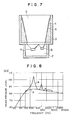
- Fig. 7 shows a fifth embodiment of the speaker system in accordance with the present invention.
- This embodiment has a high-pitch tone speaker unit 7, a low-pitch tone speaker 8, a back cavity 2, an acoustic pipe 3 for guiding the sound waves generated on the front surfaces of both speaker units 7 and 8, a partition member 6 disposed in the acoustic pipe 3 so as to define an acoustic path 5 and having slits one of which is located near the sound outlet opening of the acoustic pipe 3 while the other is in a region which is about 1/3 of the full length of the acoustic pipe as measured from the end surface of the diaphragm in the speaker unit, and a sound absorbing member 4 disposed in the space defined between the wall of the acoustic pipe 3 and the partition member 6.
- the operation of the speaker system in accordance with the fifth embodiment is as follows.
- the sound waves emitted from the rear side of the high-pitch and low-pitch tone speaker units 7 and 8 are confined in the back cavity 2 so that it does not radiate outside.
- the sound waves from the front side of the diaphragm in the speaker units 7 and 8 are guided by the acoustic pipe 3 to reach the sound outlet opening so as to be radiated therefrom.
- a portion of the sound waves reaching the sound outlet opening is reflected because the acoustic impedance is drastically changed at the sound outlet opening.
- the reflected wave tends to propagage backward towards the surface of the diaphragm.
- the reflected wave is effectively absorbed by the sound absorbing member 4 in the acoustic pipe 3 so that no standing wave is generated in the acoustic pipe.
- the partition member 6 has slits in the region near the sound outlet opening and in the region which is 1/3 of the full length of the acoustic pipe 3 as measured from the surface of the speaker diaphragm, i.e., in the regions where the particle velocity is high. It is therefore possible to selectively absorb the sound wave components of frequency regions having peaks of sound pressure. Other components of the sound wave can be guided to the sound outlet opening without being impeded by the sound absorbing member 4.
- Fig. 8 illustrates the reproduction sound pressure frequency characteristics exhibited by a speaker system with the horn or acoustic pipe in accordance with the fifth embodiment, in comparison with the characteristics exhibited by the conventional arrangement. From this Figure, it will be understood that the conventional speaker system exhibits characteristics B which includes peaks and troughs due to existence of a standing wave, while the speaker system of the fifth embodiment exhibits flat reproduction sound pressure frequency characteristics A up to high pitch region of the tone.
- the fifth embodiment also provides flat sound pressure frequency characteristics, by suppressing the peaks of sound pressure which are inevitably high in the known horn or acoustic pipe due to the presence of a standing wave.
Landscapes
- Health & Medical Sciences (AREA)
- Otolaryngology (AREA)
- Physics & Mathematics (AREA)
- Engineering & Computer Science (AREA)
- Acoustics & Sound (AREA)
- Signal Processing (AREA)
- Obtaining Desirable Characteristics In Audible-Bandwidth Transducers (AREA)
Priority Applications (1)
| Application Number | Priority Date | Filing Date | Title |
|---|---|---|---|
| EP89106833A EP0339425B1 (fr) | 1988-04-28 | 1989-04-17 | Système haut-parleur |
Applications Claiming Priority (5)
| Application Number | Priority Date | Filing Date | Title |
|---|---|---|---|
| JP63106355A JPH0775431B2 (ja) | 1988-04-28 | 1988-04-28 | スピーカシステム |
| JP106355/88 | 1988-04-28 | ||
| JP109343/88 | 1988-05-02 | ||
| JP63109343A JPH0775432B2 (ja) | 1988-05-02 | 1988-05-02 | スピーカシステム |
| EP89106833A EP0339425B1 (fr) | 1988-04-28 | 1989-04-17 | Système haut-parleur |
Publications (3)
| Publication Number | Publication Date |
|---|---|
| EP0339425A2 true EP0339425A2 (fr) | 1989-11-02 |
| EP0339425A3 EP0339425A3 (en) | 1990-01-24 |
| EP0339425B1 EP0339425B1 (fr) | 1994-03-23 |
Family
ID=26446466
Family Applications (1)
| Application Number | Title | Priority Date | Filing Date |
|---|---|---|---|
| EP89106833A Expired - Lifetime EP0339425B1 (fr) | 1988-04-28 | 1989-04-17 | Système haut-parleur |
Country Status (5)
| Country | Link |
|---|---|
| EP (1) | EP0339425B1 (fr) |
| BR (1) | BR8901979A (fr) |
| DK (1) | DK170195B1 (fr) |
| ES (1) | ES2050178T3 (fr) |
| MX (1) | MX171080B (fr) |
Cited By (8)
| Publication number | Priority date | Publication date | Assignee | Title |
|---|---|---|---|---|
| GB2302231A (en) * | 1995-03-14 | 1997-01-08 | Matsushita Electric Industrial Co Ltd | Acoustic duct for a loud speaker with a holed resonance cavity |
| GB2325586A (en) * | 1995-03-14 | 1998-11-25 | Matsushita Electric Industrial Co Ltd | An acoustic duct for a loudspeaker wherein a partition board forms a cavity with the side of the duct |
| US6008391A (en) * | 1997-03-17 | 1999-12-28 | Henkel Kommanditgesellschaft Auf Aktien | Process for preparing alkoxylated fatty acid alkyl esters |
| US6008392A (en) * | 1996-03-27 | 1999-12-28 | Henkel Kommanditgesellschaft Auf Aktien | Process for preparing alkoxylated fatty acid alkyl esters |
| US6646145B1 (en) | 1999-03-03 | 2003-11-11 | Cognis Deutschland Gmbh | Processes for preparing alkoxylated nonionic surfactants using hydrotalcite catalysts |
| GB2464512A (en) * | 2008-10-16 | 2010-04-21 | Instigate Media Ltd | Directionality of a planar ribbon loudspeaker diaphragm |
| WO2021071877A1 (fr) * | 2019-10-08 | 2021-04-15 | Bose Corporation | Haut-parleurs à pavillon |
| CN116013236A (zh) * | 2022-12-27 | 2023-04-25 | 武汉轻工大学 | 共振吸声结构及制造方法 |
Family Cites Families (5)
| Publication number | Priority date | Publication date | Assignee | Title |
|---|---|---|---|---|
| GB378286A (en) * | 1931-11-27 | 1932-08-11 | Harold Lister Kirke | Improvements in or relating to loudspeakers |
| GB496504A (en) * | 1937-06-25 | 1938-12-01 | Murphy Radio Ltd | Improvements in loud speakers |
| GB963853A (en) * | 1961-12-29 | 1964-07-15 | Wharfedale Wireless Works Ltd | Loudspeakers |
| DE1537620A1 (de) * | 1967-11-14 | 1969-12-18 | Isophon Werke Gmbh | Trichterlautsprecheraggregat |
| NZ225001A (en) * | 1987-06-16 | 1990-09-26 | Matsushita Electric Industrial Co Ltd | Loudspeaker: reflected sound waves absorbed |
-
1989
- 1989-04-17 ES ES89106833T patent/ES2050178T3/es not_active Expired - Lifetime
- 1989-04-17 EP EP89106833A patent/EP0339425B1/fr not_active Expired - Lifetime
- 1989-04-26 MX MX015811A patent/MX171080B/es unknown
- 1989-04-27 DK DK204589A patent/DK170195B1/da not_active IP Right Cessation
- 1989-04-27 BR BR898901979A patent/BR8901979A/pt not_active IP Right Cessation
Cited By (13)
| Publication number | Priority date | Publication date | Assignee | Title |
|---|---|---|---|---|
| GB2302231A (en) * | 1995-03-14 | 1997-01-08 | Matsushita Electric Industrial Co Ltd | Acoustic duct for a loud speaker with a holed resonance cavity |
| US5793000A (en) * | 1995-03-14 | 1998-08-11 | Matsushita Electric Industrial Co., Ltd. | Speaker system |
| GB2325586A (en) * | 1995-03-14 | 1998-11-25 | Matsushita Electric Industrial Co Ltd | An acoustic duct for a loudspeaker wherein a partition board forms a cavity with the side of the duct |
| GB2302231B (en) * | 1995-03-14 | 1999-01-13 | Matsushita Electric Industrial Co Ltd | Speaker system |
| GB2325586B (en) * | 1995-03-14 | 1999-01-13 | Matsushita Electric Industrial Co Ltd | Speaker system |
| US6008392A (en) * | 1996-03-27 | 1999-12-28 | Henkel Kommanditgesellschaft Auf Aktien | Process for preparing alkoxylated fatty acid alkyl esters |
| US6008391A (en) * | 1997-03-17 | 1999-12-28 | Henkel Kommanditgesellschaft Auf Aktien | Process for preparing alkoxylated fatty acid alkyl esters |
| US6646145B1 (en) | 1999-03-03 | 2003-11-11 | Cognis Deutschland Gmbh | Processes for preparing alkoxylated nonionic surfactants using hydrotalcite catalysts |
| GB2464512A (en) * | 2008-10-16 | 2010-04-21 | Instigate Media Ltd | Directionality of a planar ribbon loudspeaker diaphragm |
| GB2464512B (en) * | 2008-10-16 | 2012-11-28 | Instigate Media Ltd | A sound source |
| WO2021071877A1 (fr) * | 2019-10-08 | 2021-04-15 | Bose Corporation | Haut-parleurs à pavillon |
| US11310587B2 (en) | 2019-10-08 | 2022-04-19 | Bose Corporation | Horn loudspeakers |
| CN116013236A (zh) * | 2022-12-27 | 2023-04-25 | 武汉轻工大学 | 共振吸声结构及制造方法 |
Also Published As
| Publication number | Publication date |
|---|---|
| ES2050178T3 (es) | 1994-05-16 |
| DK170195B1 (da) | 1995-06-06 |
| DK204589A (da) | 1989-10-29 |
| EP0339425B1 (fr) | 1994-03-23 |
| BR8901979A (pt) | 1989-12-05 |
| EP0339425A3 (en) | 1990-01-24 |
| MX171080B (es) | 1993-09-29 |
| DK204589D0 (da) | 1989-04-27 |
Similar Documents
| Publication | Publication Date | Title |
|---|---|---|
| EP0295644A2 (fr) | Système de haut-parleur | |
| US7623670B2 (en) | Waveguide electroacoustical transducing | |
| EP0744880A1 (fr) | Dispositif de haut-parleur et récepteur de télévision utilisant le même | |
| US4381831A (en) | High frequency horn | |
| KR0168628B1 (ko) | 전기 음향 변환기 장치 | |
| US4493389A (en) | Speaker assembly | |
| US8615097B2 (en) | Waveguide electroacoustical transducing | |
| EP0339425A2 (fr) | Système haut-parleur | |
| US4176731A (en) | Two-section exponential acoustical horn | |
| JP3267999B2 (ja) | スピーカシステム | |
| JPH0834644B2 (ja) | スピーカシステム | |
| JP2582958B2 (ja) | スピーカーシステム | |
| JP2580383B2 (ja) | スピーカシステム | |
| JPH09307985A (ja) | スピーカ装置 | |
| JPH0775432B2 (ja) | スピーカシステム | |
| US6735320B1 (en) | Angled port loudspeaker | |
| JP3268028B2 (ja) | スピーカシステム | |
| JPH0775431B2 (ja) | スピーカシステム | |
| JPH05236583A (ja) | スピーカシステム | |
| JPH03192898A (ja) | スピーカシステム | |
| JPH05137188A (ja) | スピーカシステム | |
| JP3552321B2 (ja) | スピーカ装置 | |
| JPH06103959B2 (ja) | スピ−カシステム | |
| JPH0757037B2 (ja) | スピーカ装置およびそれを内蔵したテレビセット | |
| JPH06303688A (ja) | スピーカ装置 |
Legal Events
| Date | Code | Title | Description |
|---|---|---|---|
| PUAI | Public reference made under article 153(3) epc to a published international application that has entered the european phase |
Free format text: ORIGINAL CODE: 0009012 |
|
| AK | Designated contracting states |
Kind code of ref document: A2 Designated state(s): ES IT SE |
|
| PUAL | Search report despatched |
Free format text: ORIGINAL CODE: 0009013 |
|
| AK | Designated contracting states |
Kind code of ref document: A3 Designated state(s): ES IT SE |
|
| 17P | Request for examination filed |
Effective date: 19900427 |
|
| 17Q | First examination report despatched |
Effective date: 19920310 |
|
| GRAA | (expected) grant |
Free format text: ORIGINAL CODE: 0009210 |
|
| ITF | It: translation for a ep patent filed | ||
| AK | Designated contracting states |
Kind code of ref document: B1 Designated state(s): ES IT SE |
|
| ITTA | It: last paid annual fee | ||
| REG | Reference to a national code |
Ref country code: ES Ref legal event code: FG2A Ref document number: 2050178 Country of ref document: ES Kind code of ref document: T3 |
|
| PLBE | No opposition filed within time limit |
Free format text: ORIGINAL CODE: 0009261 |
|
| STAA | Information on the status of an ep patent application or granted ep patent |
Free format text: STATUS: NO OPPOSITION FILED WITHIN TIME LIMIT |
|
| EAL | Se: european patent in force in sweden |
Ref document number: 89106833.0 |
|
| 26N | No opposition filed | ||
| PGFP | Annual fee paid to national office [announced via postgrant information from national office to epo] |
Ref country code: SE Payment date: 20050406 Year of fee payment: 17 |
|
| PG25 | Lapsed in a contracting state [announced via postgrant information from national office to epo] |
Ref country code: SE Free format text: LAPSE BECAUSE OF NON-PAYMENT OF DUE FEES Effective date: 20060418 |
|
| EUG | Se: european patent has lapsed | ||
| PGFP | Annual fee paid to national office [announced via postgrant information from national office to epo] |
Ref country code: ES Payment date: 20080423 Year of fee payment: 20 |
|
| PGFP | Annual fee paid to national office [announced via postgrant information from national office to epo] |
Ref country code: IT Payment date: 20080426 Year of fee payment: 20 |
|
| REG | Reference to a national code |
Ref country code: ES Ref legal event code: FD2A Effective date: 20090418 |
|
| PG25 | Lapsed in a contracting state [announced via postgrant information from national office to epo] |
Ref country code: ES Free format text: LAPSE BECAUSE OF EXPIRATION OF PROTECTION Effective date: 20090418 |