EP0339537A2 - Plancher creux - Google Patents
Plancher creux Download PDFInfo
- Publication number
- EP0339537A2 EP0339537A2 EP89107342A EP89107342A EP0339537A2 EP 0339537 A2 EP0339537 A2 EP 0339537A2 EP 89107342 A EP89107342 A EP 89107342A EP 89107342 A EP89107342 A EP 89107342A EP 0339537 A2 EP0339537 A2 EP 0339537A2
- Authority
- EP
- European Patent Office
- Prior art keywords
- supports
- floor according
- support
- hollow floor
- formwork
- Prior art date
- Legal status (The legal status is an assumption and is not a legal conclusion. Google has not performed a legal analysis and makes no representation as to the accuracy of the status listed.)
- Granted
Links
Images


Classifications
-
- E—FIXED CONSTRUCTIONS
- E04—BUILDING
- E04F—FINISHING WORK ON BUILDINGS, e.g. STAIRS, FLOORS
- E04F15/00—Flooring
- E04F15/02—Flooring or floor layers composed of a number of similar elements
- E04F15/024—Sectional false floors, e.g. computer floors
- E04F15/02405—Floor panels
- E04F15/02417—Floor panels made of box-like elements
- E04F15/02423—Floor panels made of box-like elements filled with core material
- E04F15/02429—Floor panels made of box-like elements filled with core material the core material hardening after application
Definitions
- the invention relates to a hollow floor for covering a supporting floor, which has a cover layer, a support surface, supports and at least one interior extending between the supports and is at least partially formed from individual adjacent formwork elements.
- Hollow floors of this type have proven themselves in particular in the area of office spaces, in which a change in the intended use can be expected relatively frequently.
- Supply lines for example power supplies or data lines
- the interior of the hollow floor can also be used as a duct system for ventilation (heating) and ventilation.
- These supply lines are led in the area of the hollow floor to the intended place of use and penetrate the top layer there. If the intended use is changed, access to the interior is made possible after opening the installation cover and the installation lines can be removed or moved to a new consumption area.
- the hollow floors are generally created in such a way that first a formwork, which remains in place even after completion of the hollow floor, is mounted on the supporting floor and then a liquid screed is applied to the bearing surface formed by the formwork. After the screed material has hardened, it forms a single part together with the formwork.
- the formwork is made up of adjacent formwork elements educated.
- the use of known formwork has the disadvantage that the formwork elements have to be glued over the entire surface and errors can occur during this complex assembly, which can lead to parts of the screed applied flowing off into the interior.
- This has the disadvantage that the interior of the hollow floor is reduced by the penetrating screed material and is therefore not available for the laying of the supply lines and for ventilation.
- This object is achieved in that in the area of at least one side edge of the formwork element, a seal acting on another formwork element is arranged.
- the seal reliably prevents liquid screed from flowing away. It is thus ensured that no materials obstructing the installation lines can get into the interior.
- the seal is designed as a labyrinth seal.
- the labyrinth seal leads on the one hand to a reliable sealing of the formwork elements, and on the other hand the laying of the formwork elements is also made considerably easier by the interlocking labyrinth seals, since the person involved in laying the formwork elements is concerned does not have to deal with problems with the alignment of individual formwork elements. Rather, the formwork elements are aligned with each other automatically when the labyrinth seals interlock.
- the labyrinth seals are arranged crossing one another in several areas of the formwork element.
- This arrangement of the labyrinth seals stiffens the formwork elements, which makes it possible to ensure that the formwork elements can be walked on even before the screed material applied to the formwork elements has hardened.
- only the labyrinth seals arranged in the region of the side edges act with such an arrangement of the labyrinth seals.
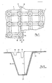
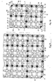
- a hollow floor essentially consists of formwork elements (1), supports (2) integrated into the formwork elements (1), one of the formwork elements (1) in the area of their vertical support surface (3) covering layer (4) and a between the Supports (2) extending interior (5) which is delimited in the vertical direction upwards by the support surface (3) and in the vertical direction below by a supporting floor (6) carrying the formwork elements (1).
- the formwork element (1) has side edges (7,8,9,1o) in the area of its lateral boundaries. In each case two of the side edges (7,8,9,10) meet in the area of corners (11,12,13,14) essentially at right angles. Seals (15, 16) are arranged in the area of the side edges (7, 8, 9, 10). The seals (15, 16) are designed as labyrinth seals (17). The seals (15) arranged in the region of the side edges (8, 9) are each formed from three beads (18) which extend essentially parallel to one another. Seals (16) arranged in the region of the side edges (7, 1o) are essentially designed as a bead (19) extending parallel to the side edge (7, 1o) assigned to them.
- the beads (18, 19, 20, 21) are essentially trapezoidal and have their greatest extent in the horizontal direction in the area of the support surface (3).
- the bead (19) extending between the beads (18, 20) has a greater extent in the vertical direction than the beads (18, 20).
- the beads (21) are in the area of their outer boundary the course of the inner boundaries Beads (2o) adjusted. The beads (2o) can thereby accommodate beads (21) that reach into them when formwork elements (1) are joined together.
- the bead (19) extends in the area of its lower limit (22) in the vertical direction essentially arcuate. As a result of this arcuate course, the bead (19) has a greater extent in the vertical direction in the area of its boundaries facing the supports (2) than in an area between these boundaries.
- the beads (18, 20, 21) run essentially tangentially to support openings (23), which are spanned by support casings (24) in the area of the support surface (3).
- the column envelopes (24) span cuboids with their essentially perpendicular center lines.
- the support openings (23) are each connected by beads (18, 19, 20) crossing them in the area of these support openings (23).
- the crosswise arrangement of the beads (18, 19, 20) stiffens the formwork elements (1).
- the beads (18, 19) run essentially tangentially to the support openings (23), the beads (19) run with their center lines through the center line of the support envelopes (24).
- an edge (25, 26) is provided between the side edges (8, 9) and the support openings (23) arranged facing them.
- the side edges (7.1o) run essentially at a distance from the beads (21) which corresponds to the distance between the beads (19) and the beads (2o).
- the pillar coverings (24) extend in conical union and have their largest diameter in the horizontal direction in the area of the pillar openings (23). In the area of their lower boundaries in the vertical direction, the support wrappings (24) of support bottoms (27) are borders.
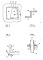
- An inspection opening (28), which is closed by an inspection cover (29), is arranged in the area of the cover layer (4).
- the inspection opening (28) is delimited in the horizontal direction by a frame (3o) which essentially consists of a base leg (31) which faces the bearing surface (3), a vertical web (32) which extends essentially in the vertical direction, and an in turn horizontal leg (33) is formed.
- the inspection cover (29) rests on the base leg (31) and essentially closes in the vertical direction at the top with the viewing leg (33).
- the frame (3o) has adjustment webs (35), in the area of which a height adjustment (36) is arranged.
- the height adjustment (36) is essentially designed as a threaded bolt (37) which engages with an external thread (38) in an internal thread (39) arranged in the region of the adjustment web (35).
- the adjustment web (35) has reinforcement webs (4o) in the area of its boundaries facing the threaded bolt (37). With its lower end in the vertical direction, the threaded bolt (37) rests on the support base (27).
- edges (25, 26) can lie in one plane with the rest of the contact surface (3). However, it is also possible to arrange the edges (25, 26) offset vertically downward relative to the rest of the bearing surface (3) and thereby also provide a substantially flat formwork element (1) resting on one another in the area of the seals (15, 16) To ensure contact surface (3) and supports (2) extending in the area of the entire extension of the formwork elements (1) to the supporting floor (6).
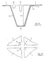
- the formwork element (1) has a corner configuration which allows more than two formwork elements (1) to rest on one another avoids.
- the formwork element (1) has bevels (41) in the area of the corners (12, 14) and a square recess (42) in the area of the corner (13).
- the bevels (41) are provided at two opposite corners (12, 14). They each have a base (50) which encloses an angle of 135 degrees with two adjacent side edges (7, 10; 8, 9).
- This base (50) runs on a support opening (51, 52) located in the area of the corner (12, 14), which is halved by the base (50).
- This diameter line spans a vertical plane, which the supports (2) arranged in the corners (12, 14) cut in half and in this way form half supports (53, 54).
- These half supports (53, 54) form a complete support (2) with corresponding half supports (55, 56) of an adjacent formwork element (57).
- the base (50) of the formwork element (1) abuts against a corresponding base (58) of the adjacent formwork element (57).
- Both the support opening (59) on the formwork element (60) and the half supports (53, 55) on the formwork elements (1, 57) are each arranged in rows (64, 65, 66) that correspond to the respective transverse edges (8, 61) or the longitudinal edge (63) are arranged in parallel.
- rows (64, 65, 66) further support openings (22; 51, 52; 59) are arranged, which are connected to each other by beads (18, 19, 20; 67, 68, 69; 70, 71, 72) .
- beads (73, 74, 75) that run parallel to the longitudinal edge (63) of the adjacent formwork element (57) snap into corresponding beads of the formwork element (60) that run parallel to the longitudinal edge (62).
- the interlocking beads (18, 19, 20; 70, 71, 72; 73, 74, 75) each form labyrinth seals that prevent the liquid screed from getting into the interior (5) when the cover layer (4) is poured.
- the half-supports (53, 55) inserted into the support opening (59) must undergo training which is dimensioned such that, after being inserted into the support opening (59), they are in a fixed contact with themselves Find the support opening (59) attached to the support (76) of the adjacent formwork element (57).
- the half-supports (53, 55) together form a support (77) which is smaller than the support (76) by at least two wall thicknesses (78) of a film (79) forming the formwork elements (1) the two half supports (53, 55) formed support (77).
- the beads (80, 81, 82; 83, 84, 85; 67, 68, 69; 73, 74, 75) adjacent to the half-supports (53, 54; 55, 56) are also designed with a smaller cross-section than the beads of the formwork element (60) which receive these beads (80, 81, 82; 83, 84, 85; 67, 68, 69; 73, 74, 75).
- a fourth formwork element (86) with the three other formwork elements (1, 57, 60) can form a complex (87) consisting of four connected formwork elements (1, 57, 60, 86).
- the fourth formwork element (86) has, at a corner (11) opposite its support opening (59), a support opening (88), the one Access to a support (89) opened.
- This support (89) has a cross section that is at least two wall thicknesses (78) smaller than the cross section of the support (77) formed from the two half supports (53, 55). In this way, the support (89) can be inserted into the support (77) formed from the two half supports (53, 55).
- the beads (18, 19, 20) formed in the area of the support (89) have a cross section that is at least two wall thicknesses (78) of the film (79) smaller than the cross section of the beads (80, 81, 82; 83, 84, 85), which are formed in the area of the half supports (53, 55). In this way, the beads (18, 19, 20) formed in the area of the support (89) can be inserted appropriately into the beads (80, 81, 82; 83, 84, 85).
- Each formwork element (1; 57; 60; 86) is expediently manufactured in such a way that it is suitable to form a complex (87) with other formwork elements (1; 57; 60; 86).
- each formwork element (1, 57, 60, 86) has supports (2, 76, 77, 89) and half supports (53, 54; 55, 56), which have dimensions of different sizes from one another.
- the half-supports (53, 54; 55, 56) each form a half cross-section (91) in the area of the bevels (41), which, with regard to the dimensions which the support (76) of the formwork element (53, 54) receiving 60) on the one hand and which the support (89) which is received within the support (77) formed by the half supports (53, 54) and which on the other hand have an average dimension.
- supports (2) of different dimensions are provided in the non-beveled corners (11, 13) of a formwork element (1).
- the corner (11) which is enclosed by the side edges (8, 9) is provided with a support (89) which has a small dimension.
- This support (89) is from the support (77) formed from the two half supports (53, 54).
- a support (76) is provided in the opposite corner (13), which has a large dimension.
- the two half supports (53, 54) have space in this support (76).
- Supports are arranged along the side edges (7, 8, 9, 10), which allow the formwork elements (1) to be joined together to form a complex (87).
- supports (92) are arranged along the longitudinal edge (9) adjacent to the support (76) and the transverse edge (10) adjacent to this support (76), which have at least medium dimensions so that they are able to support ( 93) small dimensions.
- These supports (93) extend along the side edge (7) which delimits the formwork element (1) on its side opposite the support (76).
- This support (76) receives the two half supports (51, 53) and is therefore designed as a support (94) with a large dimension.
- this support (94) the formwork elements (1, 57, 60, 86) with their respective supports (94, 92, 93) are plugged together.
- supports (93) of small dimensions are arranged along the mutually opposite side edges (8, 10) and supports (94, 92) of large and medium dimensions, into which supports (93) of small dimensions can be inserted.
- adjacent side edges (10) are supports (92) of medium size and supports (94) of large size, which are capable of small-sized supports (93).
- supports (93) of small dimensions and supports (92) of medium dimensions are arranged along the side edge (8) opposite the side edge (8), which can be inserted into the supports (92) of medium size and supports (94) of large size.
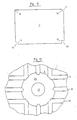
- the supports (92, 93, 94) are expediently arranged in rows (95) which extend parallel to the side edges (7, 9) running in the longitudinal direction of the formwork elements (1).
- the supports (92, 93, 94) are arranged in rows (96) which run transversely to the rows (95) and thus parallel to the transverse edges (8, 10).
- the supports (92, 93, 94) of different dimensions are arranged within the rows (95, 96) so that the formwork elements (1) can be divided into element parts (97, 98, 99, 100).
- dividing lines (101, 102) through the formwork elements (1) run parallel to the rows (95, 96).
- the formwork elements can be divided into one or more element parts (97, 98, 99, 100) along these dividing lines. Due to their size, these element parts (97, 98, 99, 100) are suitable for bridging the side distances in a specific installation case that result between a formwork element (1) and a wall (3) to which the hollow floor must be connected .
- the supports (92, 93, 94) are distributed along the dividing lines (101, 102) in the same way as along the side edges (9, 10) parallel to which extend rows (95, 96) in which supports (92) of medium size and supports (94) are arranged with large dimensions.
- a support (94) with a large dimension is specified. If the formwork element (1) is therefore subdivided along the cutting lines (101, 102), the element part (98) can be used to support columns (92) with medium dimensions and columns (93) in the area of the column (94) with large dimensions.
- supports (94) of large dimensions are provided in an area in which the cutting lines (101, 102) intersect the side edges (9, 10). In this way, a support (94) of large dimension is specified in the lower corner of the element part (98). In contrast, six supports (93) of small dimensions are provided at the top in the element part (100).
- the element parts (97, 99) each have an outer row with supports (92) of large dimensions, next to which at least one row with supports (93) of small dimensions extends.
- the dividing lines (101, 102) expediently extend next to the middle rows.
- this middle row can be provided with supports (92) of medium dimensions and supports (94) of large dimensions.
- the support (94) of large dimensions is provided at the intersection of the middle rows (95, 96) and at the intersection of the middle row extending in the longitudinal direction of the formwork element (1) with the side edge (10) along which a row (96) extends with supports (92) of medium size and supports (94) of large size.
- the cross-sections of the beads (18, 19, 20) in the immediate vicinity of the supports (92, 93, 94) are the dimensions of the supports (92, 93, 94) customized. So the beads (18, 19, 20) in the area of the supports (94) with large dimensions with a large cross cut provided. These beads of large cross-section extend to about half the distance between the support (94) and its adjacent support (92) with a medium dimension.
- the beads (18, 19, 20) which are adjacent to the supports (92) of medium size and supports (93) of small size are formed in a similar manner. In the case of directly adjacent supports (93) of small dimensions, the beads connecting these supports (93) consist exclusively of such small dimensions.
- Such a bead dimension is provided, for example, in the area of the element part (100). If supports (92) of medium size are adjacent to one another, then extend between these beads of medium size. Such an arrangement is provided, for example, in the case of the element parts (97, 99), specifically with regard to the outer rows with supports (92) of medium size.
- the formwork elements (1) are first laid on the supporting floor (6) and interlock in the area of the labyrinth seals (17). It is also possible to provide gluing or welding in the area of the labyrinth seals (17). However, it is also possible to simply let the formwork elements (1) rest on one another in the area of the seals (15, 16). After the formwork elements (1) have been laid, frames (3o) are placed at the designated locations and adjusted with the aid of the height adjustments (36) relative to the formwork elements (1) and brought into a horizontal orientation. The frame (3o) is then sealed against the formwork element (1) supporting it, for example by construction foam. In a final work step, the top layer (4) is applied to the formwork elements (1) as a liquid screed.
- the liquid screed flows into the column coverings (24) and the beads (18, 19, 20, 21). After the liquid screed has hardened, this creates a floor structure that can withstand heavy weight loads.
- the hardened deck forms in the area of the beads (17, 18, 19, 20o) layer (4) stiffening webs.
- the formwork elements (1) in the area of the inspection opening (28) are removed, for example, by being removed and access to the interior (5) is made available through the inspection opening (28). Provided supply lines can then be laid as desired between the supports (2).
- the formwork elements (1) are essentially made of a plastic.
Landscapes
- Engineering & Computer Science (AREA)
- Architecture (AREA)
- General Engineering & Computer Science (AREA)
- Civil Engineering (AREA)
- Structural Engineering (AREA)
- Floor Finish (AREA)
- Forms Removed On Construction Sites Or Auxiliary Members Thereof (AREA)
- Curing Cements, Concrete, And Artificial Stone (AREA)
- Sewage (AREA)
- Building Environments (AREA)
Priority Applications (1)
| Application Number | Priority Date | Filing Date | Title |
|---|---|---|---|
| AT89107342T ATE90762T1 (de) | 1988-04-23 | 1989-04-24 | Hohlboden. |
Applications Claiming Priority (2)
| Application Number | Priority Date | Filing Date | Title |
|---|---|---|---|
| DE3813848 | 1988-04-23 | ||
| DE3813848A DE3813848A1 (de) | 1988-04-23 | 1988-04-23 | Hohlboden |
Publications (3)
| Publication Number | Publication Date |
|---|---|
| EP0339537A2 true EP0339537A2 (fr) | 1989-11-02 |
| EP0339537A3 EP0339537A3 (fr) | 1991-01-09 |
| EP0339537B1 EP0339537B1 (fr) | 1993-06-16 |
Family
ID=6352791
Family Applications (1)
| Application Number | Title | Priority Date | Filing Date |
|---|---|---|---|
| EP89107342A Expired - Lifetime EP0339537B1 (fr) | 1988-04-23 | 1989-04-24 | Plancher creux |
Country Status (4)
| Country | Link |
|---|---|
| EP (1) | EP0339537B1 (fr) |
| AT (1) | ATE90762T1 (fr) |
| DE (3) | DE3813848A1 (fr) |
| ES (1) | ES2042860T3 (fr) |
Cited By (2)
| Publication number | Priority date | Publication date | Assignee | Title |
|---|---|---|---|---|
| EP0628678A1 (fr) * | 1993-06-08 | 1994-12-14 | Ubbink B.V. | Eléments pour planchers surélevés à auto-nivellage |
| US5373661A (en) * | 1992-04-24 | 1994-12-20 | Yugen Kaisha Clean Up System | Particularly, a structured body for the drainage treatment for the preparation for tree-planting ground, and its impounding and flushing system |
Families Citing this family (4)
| Publication number | Priority date | Publication date | Assignee | Title |
|---|---|---|---|---|
| DE4244297A1 (de) * | 1992-12-28 | 1994-06-30 | Gerhard Binder | Hohlboden |
| DE19751600C2 (de) * | 1997-11-21 | 2003-06-18 | Karl Amrhein | Verfahren und Schaltung zur Herstellung eines Estrich-Hohlbodens |
| DE10004144B4 (de) * | 2000-01-25 | 2004-10-14 | AKRO Baurevision & Systemprüfung GmbH | Verfahren zur Herstellung eines Hohl- oder Doppelbodensystems |
| DE10004145B4 (de) * | 2000-01-25 | 2004-05-19 | AKRO Baurevision & Systemprüfung GmbH | Verfahren zum Herstellen eines Estrich-Hohlbodens unter Verwendung einer verlorenen Schalung |
Family Cites Families (6)
| Publication number | Priority date | Publication date | Assignee | Title |
|---|---|---|---|---|
| US2956785A (en) * | 1957-10-04 | 1960-10-18 | Flor Heat Sales Inc | Heating panel construction |
| US3352079A (en) * | 1965-04-30 | 1967-11-14 | John G Strong | Floor form structure |
| CA1181215A (fr) * | 1981-02-04 | 1985-01-22 | Wolfgang Radtke | Plancher creux |
| DE3317683A1 (de) * | 1983-05-14 | 1984-11-15 | Schmidt Reuter Ingenieurgesellschaft mbH & Co KG, 5000 Köln | Kunststoffolienbahn als verlorene schalung fuer die herstellung des oberbodens eines hohlbodens |
| DE3325907C2 (de) * | 1983-07-19 | 1986-02-27 | Bauer, Eugen, 4600 Dortmund | Bauelement aus Kunststoff für einen Doppelboden |
| DE3405682A1 (de) * | 1984-02-17 | 1985-08-22 | H. Krantz Gmbh & Co, 5100 Aachen | Verlorene schalung |
-
1988
- 1988-04-23 DE DE3813848A patent/DE3813848A1/de not_active Ceased
- 1988-04-23 DE DE8809824U patent/DE8809824U1/de not_active Expired
-
1989
- 1989-04-24 EP EP89107342A patent/EP0339537B1/fr not_active Expired - Lifetime
- 1989-04-24 ES ES89107342T patent/ES2042860T3/es not_active Expired - Lifetime
- 1989-04-24 DE DE8989107342T patent/DE58904689D1/de not_active Expired - Fee Related
- 1989-04-24 AT AT89107342T patent/ATE90762T1/de not_active IP Right Cessation
Cited By (2)
| Publication number | Priority date | Publication date | Assignee | Title |
|---|---|---|---|---|
| US5373661A (en) * | 1992-04-24 | 1994-12-20 | Yugen Kaisha Clean Up System | Particularly, a structured body for the drainage treatment for the preparation for tree-planting ground, and its impounding and flushing system |
| EP0628678A1 (fr) * | 1993-06-08 | 1994-12-14 | Ubbink B.V. | Eléments pour planchers surélevés à auto-nivellage |
Also Published As
| Publication number | Publication date |
|---|---|
| DE8809824U1 (de) | 1988-12-22 |
| ATE90762T1 (de) | 1993-07-15 |
| EP0339537A3 (fr) | 1991-01-09 |
| ES2042860T3 (es) | 1993-12-16 |
| DE58904689D1 (de) | 1993-07-22 |
| EP0339537B1 (fr) | 1993-06-16 |
| DE3813848A1 (de) | 1989-11-02 |
Similar Documents
| Publication | Publication Date | Title |
|---|---|---|
| EP1223265A2 (fr) | Panneau de parquet | |
| DE3115026A1 (de) | Isolierelement | |
| DE2314463A1 (de) | Bodenplatte | |
| DE3815140C2 (de) | Blendrahmen zur Bildung einer Fugenschalung zwecks Verbindung von einzelnen Glasbauelementen | |
| DE69003163T2 (de) | Paneel. | |
| EP0339537A2 (fr) | Plancher creux | |
| DE3841656A1 (de) | Doppelseitig verlegbare gitterplatte aus kunststoff, insbesondere aus recycling - kunststoff | |
| DE1759372A1 (de) | Einzelplatte zur Abdeckung von Traggeruesten od.dgl. | |
| DE8804832U1 (de) | Rohr zur Ableitung von Sickerwasser von der Sohle von Deponien | |
| DE9213220U1 (de) | Dämmbahn | |
| EP3431682B1 (fr) | Profil de dilatation destiné à recevoir une tension horizontale comprenant une aile d'ancrage et une zone centrale | |
| EP0209895B1 (fr) | Panneau de plancher pour faux planchers surélevés | |
| DE3643059C2 (fr) | ||
| DE10133101A1 (de) | Fußbodenbelagselement mit Paneelen | |
| DE202004018370U1 (de) | Kontrollschacht für ein Wasserleitsystem | |
| DE4016288C2 (de) | Verfahren zum Herstellen einer polygonalen Verbundplatte für Fußböden und durch das Verfahren hergestellte Verbundplatte | |
| DE9311335U1 (de) | Bodenfliese mit Abstandshaltern | |
| DE29800244U1 (de) | Anordnung zur Lagefixierung von zu einem Bodenbelag fügbaren Paneelen | |
| DE19800375C1 (de) | Anordnung zur Lagefixierung von zu einem Bodenbelag fügbaren Paneelen | |
| AT326327B (de) | Tragsäule für baüwerke | |
| DE19602976A1 (de) | Installationsboden | |
| DE29700542U1 (de) | Feuerschutztür | |
| DE3144888A1 (de) | Daemmplatte zur waerme- und trittschallisolierung | |
| DE29907178U1 (de) | Hohlraumboden | |
| DE3027019C2 (fr) |
Legal Events
| Date | Code | Title | Description |
|---|---|---|---|
| PUAI | Public reference made under article 153(3) epc to a published international application that has entered the european phase |
Free format text: ORIGINAL CODE: 0009012 |
|
| AK | Designated contracting states |
Kind code of ref document: A2 Designated state(s): AT BE CH DE ES FR GB GR IT LI LU NL SE |
|
| PUAL | Search report despatched |
Free format text: ORIGINAL CODE: 0009013 |
|
| AK | Designated contracting states |
Kind code of ref document: A3 Designated state(s): AT BE CH DE ES FR GB GR IT LI LU NL SE |
|
| 17P | Request for examination filed |
Effective date: 19910702 |
|
| 17Q | First examination report despatched |
Effective date: 19920312 |
|
| GRAA | (expected) grant |
Free format text: ORIGINAL CODE: 0009210 |
|
| AK | Designated contracting states |
Kind code of ref document: B1 Designated state(s): AT BE CH DE ES FR GB GR IT LI LU NL SE |
|
| REF | Corresponds to: |
Ref document number: 90762 Country of ref document: AT Date of ref document: 19930715 Kind code of ref document: T |
|
| REF | Corresponds to: |
Ref document number: 58904689 Country of ref document: DE Date of ref document: 19930722 |
|
| ITF | It: translation for a ep patent filed | ||
| GBT | Gb: translation of ep patent filed (gb section 77(6)(a)/1977) |
Effective date: 19930923 |
|
| ET | Fr: translation filed | ||
| REG | Reference to a national code |
Ref country code: GR Ref legal event code: FG4A Free format text: 3009094 |
|
| REG | Reference to a national code |
Ref country code: ES Ref legal event code: FG2A Ref document number: 2042860 Country of ref document: ES Kind code of ref document: T3 |
|
| PLBE | No opposition filed within time limit |
Free format text: ORIGINAL CODE: 0009261 |
|
| STAA | Information on the status of an ep patent application or granted ep patent |
Free format text: STATUS: NO OPPOSITION FILED WITHIN TIME LIMIT |
|
| PGFP | Annual fee paid to national office [announced via postgrant information from national office to epo] |
Ref country code: LU Payment date: 19940531 Year of fee payment: 6 |
|
| 26N | No opposition filed | ||
| EPTA | Lu: last paid annual fee | ||
| EAL | Se: european patent in force in sweden |
Ref document number: 89107342.1 |
|
| PGFP | Annual fee paid to national office [announced via postgrant information from national office to epo] |
Ref country code: FR Payment date: 19950421 Year of fee payment: 7 |
|
| PG25 | Lapsed in a contracting state [announced via postgrant information from national office to epo] |
Ref country code: LU Free format text: LAPSE BECAUSE OF NON-PAYMENT OF DUE FEES Effective date: 19950424 |
|
| PGFP | Annual fee paid to national office [announced via postgrant information from national office to epo] |
Ref country code: GB Payment date: 19950424 Year of fee payment: 7 |
|
| PGFP | Annual fee paid to national office [announced via postgrant information from national office to epo] |
Ref country code: AT Payment date: 19950425 Year of fee payment: 7 |
|
| PGFP | Annual fee paid to national office [announced via postgrant information from national office to epo] |
Ref country code: GR Payment date: 19950427 Year of fee payment: 7 |
|
| PGFP | Annual fee paid to national office [announced via postgrant information from national office to epo] |
Ref country code: SE Payment date: 19950428 Year of fee payment: 7 Ref country code: ES Payment date: 19950428 Year of fee payment: 7 |
|
| PGFP | Annual fee paid to national office [announced via postgrant information from national office to epo] |
Ref country code: NL Payment date: 19950430 Year of fee payment: 7 |
|
| PGFP | Annual fee paid to national office [announced via postgrant information from national office to epo] |
Ref country code: BE Payment date: 19950530 Year of fee payment: 7 |
|
| PG25 | Lapsed in a contracting state [announced via postgrant information from national office to epo] |
Ref country code: GB Effective date: 19960424 Ref country code: AT Effective date: 19960424 |
|
| PG25 | Lapsed in a contracting state [announced via postgrant information from national office to epo] |
Ref country code: SE Effective date: 19960425 Ref country code: ES Free format text: LAPSE BECAUSE OF THE APPLICANT RENOUNCES Effective date: 19960425 |
|
| PG25 | Lapsed in a contracting state [announced via postgrant information from national office to epo] |
Ref country code: BE Effective date: 19960430 |
|
| BERE | Be: lapsed |
Owner name: BINDER GERHARD Effective date: 19960430 |
|
| PG25 | Lapsed in a contracting state [announced via postgrant information from national office to epo] |
Ref country code: GR Free format text: THE PATENT HAS BEEN ANNULLED BY A DECISION OF A NATIONAL AUTHORITY Effective date: 19961031 |
|
| PG25 | Lapsed in a contracting state [announced via postgrant information from national office to epo] |
Ref country code: NL Effective date: 19961101 |
|
| REG | Reference to a national code |
Ref country code: GR Ref legal event code: MM2A Free format text: 3009094 |
|
| GBPC | Gb: european patent ceased through non-payment of renewal fee |
Effective date: 19960424 |
|
| REG | Reference to a national code |
Ref country code: CH Ref legal event code: PL |
|
| PG25 | Lapsed in a contracting state [announced via postgrant information from national office to epo] |
Ref country code: FR Effective date: 19961227 |
|
| NLV4 | Nl: lapsed or anulled due to non-payment of the annual fee |
Effective date: 19961101 |
|
| EUG | Se: european patent has lapsed |
Ref document number: 89107342.1 |
|
| REG | Reference to a national code |
Ref country code: FR Ref legal event code: ST |
|
| PG25 | Lapsed in a contracting state [announced via postgrant information from national office to epo] |
Ref country code: LI Free format text: LAPSE BECAUSE OF NON-PAYMENT OF DUE FEES Effective date: 19970131 Ref country code: CH Free format text: LAPSE BECAUSE OF NON-PAYMENT OF DUE FEES Effective date: 19970131 |
|
| PGFP | Annual fee paid to national office [announced via postgrant information from national office to epo] |
Ref country code: CH Payment date: 19970303 Year of fee payment: 8 |
|
| REG | Reference to a national code |
Ref country code: ES Ref legal event code: FD2A Effective date: 19991102 |
|
| PGFP | Annual fee paid to national office [announced via postgrant information from national office to epo] |
Ref country code: DE Payment date: 20021031 Year of fee payment: 14 |
|
| PG25 | Lapsed in a contracting state [announced via postgrant information from national office to epo] |
Ref country code: DE Free format text: LAPSE BECAUSE OF NON-PAYMENT OF DUE FEES Effective date: 20031101 |
|
| PG25 | Lapsed in a contracting state [announced via postgrant information from national office to epo] |
Ref country code: IT Free format text: LAPSE BECAUSE OF NON-PAYMENT OF DUE FEES;WARNING: LAPSES OF ITALIAN PATENTS WITH EFFECTIVE DATE BEFORE 2007 MAY HAVE OCCURRED AT ANY TIME BEFORE 2007. THE CORRECT EFFECTIVE DATE MAY BE DIFFERENT FROM THE ONE RECORDED. Effective date: 20050424 |