EP0339614A2 - Dispensateur de bouteilles - Google Patents
Dispensateur de bouteilles Download PDFInfo
- Publication number
- EP0339614A2 EP0339614A2 EP89107566A EP89107566A EP0339614A2 EP 0339614 A2 EP0339614 A2 EP 0339614A2 EP 89107566 A EP89107566 A EP 89107566A EP 89107566 A EP89107566 A EP 89107566A EP 0339614 A2 EP0339614 A2 EP 0339614A2
- Authority
- EP
- European Patent Office
- Prior art keywords
- ring
- piston unit
- bottle dispenser
- scale ring
- cylinder
- Prior art date
- Legal status (The legal status is an assumption and is not a legal conclusion. Google has not performed a legal analysis and makes no representation as to the accuracy of the status listed.)
- Withdrawn
Links
Images
Classifications
-
- G—PHYSICS
- G01—MEASURING; TESTING
- G01F—MEASURING VOLUME, VOLUME FLOW, MASS FLOW OR LIQUID LEVEL; METERING BY VOLUME
- G01F11/00—Apparatus requiring external operation adapted at each repeated and identical operation to measure and separate a predetermined volume of fluid or fluent solid material from a supply or container, without regard to weight, and to deliver it
- G01F11/02—Apparatus requiring external operation adapted at each repeated and identical operation to measure and separate a predetermined volume of fluid or fluent solid material from a supply or container, without regard to weight, and to deliver it with measuring chambers which expand or contract during measurement
- G01F11/021—Apparatus requiring external operation adapted at each repeated and identical operation to measure and separate a predetermined volume of fluid or fluent solid material from a supply or container, without regard to weight, and to deliver it with measuring chambers which expand or contract during measurement of the piston type
- G01F11/023—Apparatus requiring external operation adapted at each repeated and identical operation to measure and separate a predetermined volume of fluid or fluent solid material from a supply or container, without regard to weight, and to deliver it with measuring chambers which expand or contract during measurement of the piston type with provision for varying the stroke of the piston
Definitions
- the invention relates to a bottle dispenser for aspirating and dispensing liquid according to the preamble of claim 1.
- Such a bottle dispenser is known from DE-PS 30 31 830. It consists of a cylinder and a piston unit with a piston which is guided in a longitudinally displaceable manner in the cylinder, a handle and a guide sleeve which surrounds the cylinder and runs coaxially to the outer circumferential surface of the cylinder.
- An outer sleeve is arranged coaxially outside the guide sleeve and is connected to the piston unit in an axially fixed and radially rotatable manner.
- a stop body is arranged in the manner of a sliding block in a respective axial groove formed in the sleeves and a helical groove. The stop body works together with a counter stop provided on the cylinder.
- the axial groove on the inner wall of the outer sleeve and the helical groove in the guide sleeve preferably as a continuous slot forms is. It is also possible to form the axial groove as a continuous slot in the guide sleeve and the helical groove on the inner wall of the outer sleeve by way of kinematic reversal.
- the details of the known bottle dispenser can be found in DE-PS 30 31 830.
- the known bottle dispenser also has a scale ring which is firmly connected to the piston unit. For example, it can be connected in one piece to the handle at its lower end.
- the rotation of the scale ring corresponds to the rotation of the piston unit.
- the angle of rotation of the relative rotation between the outer sleeve and the piston unit is at most 360 °.
- the pitch of the helical groove can be reduced. If the total stroke of the piston is relatively small, it may be possible to accommodate a relatively flat helical groove with just a single full rotation. With a larger piston stroke, however, the pitch of the helical groove increases to the same extent if, as before, only a single full rotation is permitted between the outer sleeve and the piston unit. In certain cases, however, it is desirable to be able to provide a smaller pitch for the helical groove, for example in order to achieve self-locking.
- the object of the invention is to provide a bottle dispenser of the type specified at the beginning, with which an accurate and smooth adjustment of the volume of liquid to be dispensed and, at the same time, a perfect reading of the set one Volume of liquid is possible.
- the scale ring is axially fixed and radially rotatable both to the piston unit and to the outer sleeve. It is connected to the piston unit by a reduction gear such that a smaller angle of rotation of the piston unit corresponds to a smaller angle of rotation of the scale ring.
- the reduction ratio of the reduction gear is adjusted so that the total angle of rotation of the scale ring relative to the outer sleeve is at most 360 °.
- the relative rotation between the piston unit and the outer sleeve can be more than a full angle.
- the reduction gear can be designed such that the reduction ratio is 2.5.
- the helical groove can then be designed so that it extends over 2 1/2 full turns.
- the piston unit can then be rotated 2 1/2 turns relative to the outer sleeve. Due to the reduction ratio of 2.5, the scale ring can rotate a maximum of 360 ° relative to the outer sleeve. There is a marking on the outer sleeve that works with a scale on the scale ring.
- the pitch of the helical grooves can be kept low, which ensures an accurate and smooth setting. Furthermore, the slight incline prevents the train from being adjusted independently (self-locking).
- a correct reading of the set liquid volume is possible in that the reduction gear can be adjusted in such a way that the scale ring can be rotated by at most 360 ° relative to the outer sleeve. Each angular position of the scale ring relative to the outer sleeve thus clearly corresponds to a single position of the stop body. With a helical groove that extends over 360 °, the operator must So do not notice whether a full revolution has already been completed or not.
- the scale ring can be connected to the handle of the piston unit. A particularly simple design results if the scale ring is guided in a groove on the underside of the handle.
- the scale ring is advantageously mounted in a shoulder on the upper, radially outer end of the outer sleeve.
- the outer circumference of the scale ring is then flush with the outer circumference of the outer sleeve, which gives the entire dispenser an attractive appearance. Furthermore, this type of storage is particularly easy to implement.
- the reduction gear can consist of a gear transmission.
- two intermeshing gear wheels are rotatably mounted about vertical axes running at a radial distance, of which the radially outer one with an inner toothed ring firmly connected to the scale ring and the radially inner one with combs an external ring gear firmly connected to the piston unit. Due to the use of two intermeshing gear wheels, there is no reversal of the direction of rotation between the piston unit or the grip piece on the one hand and the scale ring on the other hand. This also applies to integer multiples of two gear wheels. With only two gears, the missing reversal of the direction of rotation can be achieved with the least effort.
- the inner ring gear is formed on the inside of an intermediate ring which is glued to the scale ring.
- the adhesive can be selected so that it only hardens after a certain time. It is possible to first set the zero point of the scale exactly; a relative movement can take place between the scale ring and the intermediate ring. The adhesive is then allowed to harden in the rest position of the dispenser. This creates the fixed connection between the intermediate ring and the scale ring. After the adhesive has hardened, the adjusted bottle dispenser is ready for use.
- the outer ring gear of the gear transmission can be formed on the outside of the upper end of the guide sleeve. It is particularly advantageous that the upper end of the outer ring gear of the guide sleeve engages in an inner ring gear of the handle. The outer ring gear of the guide sleeve is thus extended beyond the axial length of the ring gear of one gear. Due to the intermeshing of the outer ring gear of the guide sleeve and the inner ring gear of the handle, the guide sleeve is connected to the handle in a rotationally fixed manner; at the same time there is some play in the axial direction.
- the handle can have an axial central bore through which a clamping screw that can be screwed to a central thread of the guide sleeve runs.
- a clamping screw that can be screwed to a central thread of the guide sleeve runs.
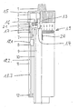
- the bottle dispenser is shown in section on the left of the dash-dotted central axis, while it is shown on the right of it in a view.
- the bottle dispenser consists of a cylinder 10, the lower end of which is firmly connected to a valve head.
- a valve head For a more detailed design of this valve head, reference is made to DE-PS 30 31 830.
- a piston 9 is guided in a longitudinally displaceable manner in the cylinder. By moving the piston 9 inside the cylinder 10 upward, liquid is sucked into the cylinder. This liquid is then displaced out of the cylinder again by a subsequent movement of the piston and released from the bottle dispenser.
- the inner sleeve 6 is connected to the piston 9.
- the guide sleeve 6 has an upwardly projecting cylindrical pin 13, which has an external ring gear on its outside. Furthermore, an internal thread 14 is present in the pin 13 of the guide sleeve 6.
- the knob 2 is thus non-rotatable with the pin 13 of the guide sleeve 6 connected.
- the rotary knob 2 has an axial central bore 15 through which the clamping screw 1, which can be screwed to the central thread 14 of the guide sleeve 6, runs.
- the clamping screw 1 has an upper part which is larger in diameter and rests with a shoulder on the upper end surface of the rotary knob 2, and a lower part which carries a thread. With this thread, the clamping screw 1 is screwed to the internal thread 14 of the pin 13 of the guide sleeve 6.
- Stop bodies 8 are arranged both in the helical grooves 18.1-18.3 in the inner surface of the outer sleeve 11 and in the axial slots of the inner sleeve 6.
- the stop body 8 has at its radially outer end a projection which engages in a corresponding helical groove 18.1. Furthermore, it has a substantially rectangular cross-sectional area, so that it can slide up and down in an axially extending slot in the inner sleeve.
- a part of the stop body projects into the area between the guide sleeve 6 and the cylinder 10. This part serves as a stop on the counter stop 7, which is connected to the cylinder 10 at the upper end thereof. The stop of the stop body 8 on the counter stop 7 thus limits the upward movement of the stop body 8.
- the stop body 8 moves up or down when the guide sleeve 6 is rotated relative to the outer sleeve 11.
- the path of the stop body 8 is down limited by the guide ring 12 which is connected to the guide sleeve 6 with a snap lock.
- the axial distance of the upper edge of the stop body 8 from the lower edge of the counter-stop 7 determines the stroke of the dispenser and thus the volume of liquid sucked in.
- this stroke and thus the volume of liquid to be sucked in can be changed via an axial movement of the stop nut 8.
- a rotation of the guide sleeve 6 is achieved by rotating the rotary knob 2, since this rotary knob 2 is connected to the guide sleeve 6 in an axially rotationally fixed manner.
- the piston unit is formed by the piston 9, the guide sleeve 6 and the handle 2. In its lower region, the guide sleeve 6 runs coaxially to the outer circumferential surface of the cylinder 10.
- the scale ring 5 carries a scale 19 on its outer circumferential surface.
- a marking 20 is made on the outer surface of the outer sleeve 11 in the vicinity of the scale 19 so that the scale setting can be read.
- the outer sleeve 11 is arranged coaxially outside of the guide sleeve 6 and connected to the piston unit, consisting of piston 9, guide sleeve 6 and rotary knob 2, axially fixed and radially rotatable.
- the scale ring 5 is axially fixed and radially rotatable both to the piston unit and to the outer sleeve 11. Furthermore, the scale ring 5 with the piston unit, consisting of piston 9, guide sleeve 6 and rotary knob 2, is through a reduction gear connected so that a certain angle of rotation of the piston unit corresponds to a smaller angle of rotation of the scale ring 5.
- the reduction gear consists of a gear transmission.
- two intermeshing gearwheels 3 are provided, which are rotatably mounted about vertical axes running at a radial distance.
- the bearing of the gears 3 is formed by circular cylindrical depressions in the upper surface of the flange 21.
- the radially outer gear 3 meshes with an internal ring gear which is formed on the inside of the intermediate ring 4, which in turn is glued to the scale ring 5.
- the internal ring gear is thus firmly connected to the scale ring 5.
- the radially inner gear 3 meshes with the outer ring gear on the outer circumferential surface of the pin 13 of the guide sleeve 6, that is to say with an outer ring gear fixedly connected to the piston unit.
- pairs of gearwheels can be arranged over the circumference of the flange 21.
- the outer sleeve 11 is held in place and the rotary knob 2 is turned. So there is a relative rotation between the knob 2 and the outer sleeve 11.
- the guide sleeve 6 is rotated with the rotary knob 2.
- the stop body 8 moves - depending on the direction of rotation - up or down.
- the gears 3 are set in rotation. They drive the scale ring 5 via the inner ring gear of the intermediate ring 4.
- the scale ring 5 thus rotates when the rotary knob 2 is rotated relative to the outer sleeve 11 both relative to the rotary knob 2 and also relative to the outer sleeve 11.
- the scale ring 5 rotates more slowly than the rotary knob 2 due to the reduction ratio. It is therefore possible to use the dispenser in this way to coordinate that several rotations of the rotary knob 2 correspond only to a single full rotation of the scale ring 5. Through this an unambiguous assignment of the scale ring 5 or the scale 19 to the marking 20 is always guaranteed. At the same time, it is possible to design the helical grooves 18.1 - 18.3 with a relatively flat slope, so that an accurate and smooth adjustment is ensured and an independent adjustment to tension is prevented (self-locking).
- the clamping screw 1 makes it possible for the volume once set to be firmly locked between the outer sleeve 11 and the rotary knob 2 by tightening the scale ring 5 and / or the intermediate ring 4.
- the guide sleeve 6 and, with it, the flange 21, the outer sleeve 11 with its shoulder 17 are moved towards the rotary knob 2 and its groove 16.
- the scale ring 5 is thus clamped between the outer sleeve 11 and the rotary knob 2, so that the set stroke volume cannot be inadvertently adjusted. If the liquid volume is to be adjusted again, the clamping screw 1 is loosened and adjustment is possible again.
- the scale 19 of the scale ring 5 can be adjusted relative to the marking 20 of the outer sleeve 11.
- an adhesive with a certain curing time is introduced between the intermediate ring 4 and the scale ring 5. Then, before the adhesive has hardened, the scale ring 5, outer sleeve 11 and rotary knob 2, including the guide sleeve 6, are brought into the correct positions. Then wait until the adhesive has hardened. The dispenser is then - correctly adjusted - ready to use.
- the entire volume range can be scanned with, for example, two revolutions, it is self-locking due to the relatively small pitch of the helical grooves, and it also has a locking screw.
- the stop body 8 moves in the guide grooves 18.1-18.3 of the outer sleeve 11, driven by the axial slots of the guide sleeve 6, up or down. Since the cylinder 10, to which the counter stop ring 7 is firmly glued at the upper end, is connected to the valve head (cf. DE-PS 30 31 830), the stroke of the piston 9 can be adjusted continuously. The volume to be metered is determined by the diameter of the cylinder 10 and the stroke. This volume to be metered can then be read on the scale 19.
- the scale ring 5 was reduced to 1: 2.5 with respect to the rotary knob 2 via a planetary gear 3.
- the small pitch of the helical grooves prevents the cable from being adjusted independently.
- the set volume can be firmly locked by means of the clamping screw 1 by tightening the scale ring 5 between the outer sleeve 11 and the rotary knob 2.
- the guide sleeve 6 is connected to the rotary knob 2 via a toothing that allows axial play.
- the guide ring 12 which is connected to the lower end of the guide sleeve 6 by a snap lock, prevents the stop body 8 from being unscrewed.
- the scale ring 5 is fixed with the intermediate ring 4 carrying the internal ring gear after adjustment of the volume, for example by curing an adhesive.
Landscapes
- Physics & Mathematics (AREA)
- Fluid Mechanics (AREA)
- General Physics & Mathematics (AREA)
- Containers And Packaging Bodies Having A Special Means To Remove Contents (AREA)
- Reciprocating Pumps (AREA)
Applications Claiming Priority (2)
| Application Number | Priority Date | Filing Date | Title |
|---|---|---|---|
| DE3814076 | 1988-04-26 | ||
| DE19883814076 DE3814076A1 (de) | 1988-04-26 | 1988-04-26 | Flaschendispenser |
Publications (2)
| Publication Number | Publication Date |
|---|---|
| EP0339614A2 true EP0339614A2 (fr) | 1989-11-02 |
| EP0339614A3 EP0339614A3 (fr) | 1990-09-26 |
Family
ID=6352914
Family Applications (1)
| Application Number | Title | Priority Date | Filing Date |
|---|---|---|---|
| EP19890107566 Withdrawn EP0339614A3 (fr) | 1988-04-26 | 1989-04-26 | Dispensateur de bouteilles |
Country Status (2)
| Country | Link |
|---|---|
| EP (1) | EP0339614A3 (fr) |
| DE (1) | DE3814076A1 (fr) |
Cited By (3)
| Publication number | Priority date | Publication date | Assignee | Title |
|---|---|---|---|---|
| DE4219947A1 (de) * | 1992-06-18 | 1993-12-23 | Kugler Julius & Co Gmbh | Portioniereinrichtung für Medien |
| EP0843161A1 (fr) * | 1996-11-16 | 1998-05-20 | Brand GmbH + Co | Distributeur montable sur une bouteille |
| CN112089339A (zh) * | 2020-09-11 | 2020-12-18 | 常熟理工学院 | 定量型油壶 |
Families Citing this family (1)
| Publication number | Priority date | Publication date | Assignee | Title |
|---|---|---|---|---|
| DE4137351C2 (de) * | 1991-11-13 | 1997-01-16 | Walu Apparatetechnik Gmbh | Flaschendispenser |
Family Cites Families (4)
| Publication number | Priority date | Publication date | Assignee | Title |
|---|---|---|---|---|
| CH607620A5 (fr) * | 1977-03-07 | 1978-09-29 | Contraves Ag | |
| DE3031830C2 (de) * | 1980-08-23 | 1983-02-17 | Witeg-Glasgeräte Helmut Antlinger KG, 6980 Wertheim | Flaschendispenser |
| CH643145A5 (fr) * | 1981-06-09 | 1984-05-30 | Socorex Isba Sa | Dispositif pour prelever un volume predetermine et reglable de liquide dans un recipient. |
| DE3208436C2 (de) * | 1982-02-22 | 1985-09-26 | Glasgerätebau Hirschmann, 7101 Eberstadt | Flaschendispenser |
-
1988
- 1988-04-26 DE DE19883814076 patent/DE3814076A1/de active Granted
-
1989
- 1989-04-26 EP EP19890107566 patent/EP0339614A3/fr not_active Withdrawn
Cited By (4)
| Publication number | Priority date | Publication date | Assignee | Title |
|---|---|---|---|---|
| DE4219947A1 (de) * | 1992-06-18 | 1993-12-23 | Kugler Julius & Co Gmbh | Portioniereinrichtung für Medien |
| EP0843161A1 (fr) * | 1996-11-16 | 1998-05-20 | Brand GmbH + Co | Distributeur montable sur une bouteille |
| US5957330A (en) * | 1996-11-16 | 1999-09-28 | Brand Gmbh + Co. | Bottle top dispenser |
| CN112089339A (zh) * | 2020-09-11 | 2020-12-18 | 常熟理工学院 | 定量型油壶 |
Also Published As
| Publication number | Publication date |
|---|---|
| DE3814076A1 (de) | 1989-11-09 |
| DE3814076C2 (fr) | 1990-10-18 |
| EP0339614A3 (fr) | 1990-09-26 |
Similar Documents
| Publication | Publication Date | Title |
|---|---|---|
| DE69828482T2 (de) | Eine eine kippbare mutter aufweisende spritze | |
| EP0831947B1 (fr) | Dispositif d'injection | |
| DE69131462T2 (de) | Mehrkomponenten spender mit verwählbarem mischungsverhältnis | |
| EP3102254B1 (fr) | Dispositif d'injection | |
| EP0649678A1 (fr) | Pipette à piston | |
| DE19717107A1 (de) | Antriebsvorrichtung für einen Kolben in einem ein Medikamentfluid enthaltenden Behältnis | |
| WO1993016740A2 (fr) | Appareil d'injection | |
| WO2009062686A1 (fr) | Système d'injection à accouplement activé par actionnement | |
| DE19804354B4 (de) | Spritzenpumpe | |
| DE69116355T2 (de) | Prozedur zum verriegeln der verstellvorrichtung einer pipette, und pipette | |
| DE3520502C2 (de) | Antriebsvorrichtung für Ventile | |
| DE2334571C3 (de) | Hahnbetätigungsvorrichtung | |
| DE2920133C2 (de) | Hubvorrichtung mit mindestens zwei gegeneinander teleskopartig ausfahrbaren Gewindespindeln | |
| WO2006114010A1 (fr) | Compensation de longueur pour un dispositif de reglage d'un dispositif d'injection | |
| DE3814076C2 (fr) | ||
| CH665197A5 (de) | Einrichtung zum bewickeln von bikonusspulen oder spulen mit aehnlichen flanschformen. | |
| DE69737038T2 (de) | Stufenweise einstellbare dosierungsspritze | |
| DE2756395A1 (de) | Reversierbarer antriebsmechanismus fuer ratschenschluessel | |
| EP2219713A1 (fr) | Système d'injection à accouplement activé par actionnement | |
| DE2705655A1 (de) | Vorrichtung zur dosierten abgabe viskoser massen | |
| DE3639763A1 (de) | Tisch-vorschubvorrichtung | |
| DE4122675C2 (de) | Bewegungsübertragungsvorrichtung für die Heizanlage eines Kraftfahrzeugs | |
| DE2011576C3 (de) | Stationswähler für Hochfrequenznachrichtengeräte | |
| EP1558307A1 (fr) | Dispositif d'administration d'un produit injectable | |
| DE29923222U1 (de) | Greifereinheit für eine automatische Probenöffnungsvorrichtung |
Legal Events
| Date | Code | Title | Description |
|---|---|---|---|
| PUAI | Public reference made under article 153(3) epc to a published international application that has entered the european phase |
Free format text: ORIGINAL CODE: 0009012 |
|
| AK | Designated contracting states |
Kind code of ref document: A2 Designated state(s): DE ES FR GB IT |
|
| PUAL | Search report despatched |
Free format text: ORIGINAL CODE: 0009013 |
|
| AK | Designated contracting states |
Kind code of ref document: A3 Designated state(s): DE ES FR GB IT |
|
| 17P | Request for examination filed |
Effective date: 19901129 |
|
| 17Q | First examination report despatched |
Effective date: 19920527 |
|
| STAA | Information on the status of an ep patent application or granted ep patent |
Free format text: STATUS: THE APPLICATION IS DEEMED TO BE WITHDRAWN |
|
| 18D | Application deemed to be withdrawn |
Effective date: 19921007 |