EP0339687A1 - Entraînement d'une bande dans une cassette - Google Patents
Entraînement d'une bande dans une cassette Download PDFInfo
- Publication number
- EP0339687A1 EP0339687A1 EP89109132A EP89109132A EP0339687A1 EP 0339687 A1 EP0339687 A1 EP 0339687A1 EP 89109132 A EP89109132 A EP 89109132A EP 89109132 A EP89109132 A EP 89109132A EP 0339687 A1 EP0339687 A1 EP 0339687A1
- Authority
- EP
- European Patent Office
- Prior art keywords
- cartridge
- loading
- housing
- path
- tape drive
- Prior art date
- Legal status (The legal status is an assumption and is not a legal conclusion. Google has not performed a legal analysis and makes no representation as to the accuracy of the status listed.)
- Granted
Links
Images


Classifications
-
- G—PHYSICS
- G11—INFORMATION STORAGE
- G11B—INFORMATION STORAGE BASED ON RELATIVE MOVEMENT BETWEEN RECORD CARRIER AND TRANSDUCER
- G11B15/00—Driving, starting or stopping record carriers of filamentary or web form; Driving both such record carriers and heads; Guiding such record carriers or containers therefor; Control thereof; Control of operating function
- G11B15/18—Driving; Starting; Stopping; Arrangements for control or regulation thereof
- G11B15/1883—Driving; Starting; Stopping; Arrangements for control or regulation thereof for record carriers inside containers
-
- G—PHYSICS
- G11—INFORMATION STORAGE
- G11B—INFORMATION STORAGE BASED ON RELATIVE MOVEMENT BETWEEN RECORD CARRIER AND TRANSDUCER
- G11B15/00—Driving, starting or stopping record carriers of filamentary or web form; Driving both such record carriers and heads; Guiding such record carriers or containers therefor; Control thereof; Control of operating function
- G11B15/675—Guiding containers, e.g. loading, ejecting cassettes
- G11B15/6751—Guiding containers, e.g. loading, ejecting cassettes with movement of the cassette parallel to its main side, i.e. front loading
- G11B15/67521—Guiding containers, e.g. loading, ejecting cassettes with movement of the cassette parallel to its main side, i.e. front loading of cassette with internal belt drive
Definitions
- This invention relates to digital magnetic tape drives in general and particularly concerns a compact drive for standard tape cartridges similar to the type described in American Standard ANSI X3.55 - 1977 and U.S. Patent No. 3,692,255 entitled "Belt Driven Tape Cartridge”.
- Prior art tape drives are available which are capable of accommodating endwise loading of the standard 1/4" tape cartridge.
- the prior art devices have complicated mechanisms for opening the tape access door of the standard cartridge after loading.
- the prior art end-loading drives shift the magnetic head and tape drive motor into engagement with the loaded cartridge in order to actuate the drive. This shifting movmement of the drive motor and the head is necessary because the end-loading feature does not permit engagement of these components in the normal manner.
- a problem with this approach is that the positional accuracy and repeatability requirements for the head and the motor with respect to the cartridge are such that expensive and complicated support mechanisms must be provided in order to permit swinging movement of these components while still maintaining the specified positional and repeatability tolerances.
- US-A-3 604 862 discloses a tape cartridge positioning apparatus comprising a reciprocating lever having front and rear arms between which the tape cartridge is received.
- One of said arms projects from the housing of the apparatus and is manually movable to move said lever longitudinally against a spring bias after the tape cartridge has been fully inserted into the apparatus to displace the tape cartridge in a direction at right angles to the loading direction to bring the tape into engagement with a magnetic head.
- said projecting arm to move the tape cartridge towards the magnetic head.
- the device of the present application overcomes the aforementioned problems by providing a mechanism which is operated simply by movement of the tape cartridge in its loading direction and which eliminates the need to shift the magnetic head and the drive motor to operably engage the cartridge after loading.
- the present invention provides for shifting of the cartridge, after it is loaded, to a position wherein it is in engagement with both the drive motor and the magnetic head of the drive. Consequently, the magnetic head and drive motor do not need to be specially supported or moved transverse relative to the cartridge within the drive.
- the invention of the present application also eleminates power transmission problems by positioning the drive motor in direct drive relationship with the cartridge.
- the present invention provides a tape drive for a digital magnetic cartridge of the type having a generally flat rectangular body comprising a pair of mutually spaced ends interconnecting a pair of elongated sides, a longitudinal axis intersecting said ends, and a tape access opening in one of said sides; said drive including: a housing adapted to receive said cartridge by manual loading; means defining a generally rectilinear loading path of travel within said housing for said cartridge; a magnetic head mounted in said housing adjacent said path; said housing having a loading slot configured to permit only endwise insertion of the cartridge into the housing thereby requiring lengthwise movement of the cartridge to follow along said loading path of travel, means for shifting said cartridge transversely of said generally rectilinear loading path to and from engagement with said magnetic head after the cartridge has been inserted endwise into said housing and has traversed at least a portion of said rectilinear loading path, characterised in said shifting means including a cartridge carriage pivotally mounted within said housing for swinging said cartridge transversely of said loading path toward and away from
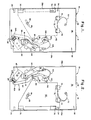
- FIGs 1 and 2 there is shown top and bottom plan views respectively of a digital magnetic tape drive adapted for use with a conventional digital magnetic tape cartridge 12 as broadly shown in Figure 5.
- the drive 10 comprises a housing 14 (portions of which have been deleted to reveal details of construction of the drive (10), a magnetic head 16 supported within the housing 14, a cartridge-receiving carriage assembly 18, and a door-opening mechanism 20 for facilitating loading of the cartridge 12 into drive 10 as will be described.
- the drive 10 also includes a motor (not shown) adapted to operably engage the cartridge 12 during operation of the drive 10; the location of the motor capstan relative to the other components of the drive 10 is shown for reference purposes in broken lines in the drawing and is designated by the numeral 22 ( Figures 6 to 9).
- the housing 14 has opposed front and back walls 24 and 26, respectively and a spaced pair of sidewalls 28a, and 28b extending between the walls 24 and 26.
- the housing 14 is also provided with a flat, normally horizontally disposed partition 30 having a top surface 32 and a bottom surface 33.
- the partition 30 is contiguous with the walls 24, 26 and 28 approximately mid-height thereof.
- the housing 14 has a flat bottom 36 and a top cover 38 to form an enclosure for the other components of the drive 10.
- a slot (not shown) in the front wall 24 is configured to permit only endwise loading of the cartridge 12 into the housing 14.
- the cartridge 12 is generally described in American National Standard ANSI 3.55-1977 entitled "Unrecorded Magnetic Tape Cartridge For Information Interchange, 0.250 inch (6.30 millimeter), 1600 BPI (63BPMM), Phase EnCoded" which standard is hereby incorporated by reference.
- the cartridge 12 has a generally flat rectangular body 40 presenting a frontal edge 42, a rear edge 44 and a pair of ends 46 and 48, respectively.
- An access opening 50 in the front edge 42 on the body 40 permits acccess to the tape 52 carried on spaced reels 54 and 56, respectively.
- a channel-shaped door 51 normally covers the access opening 50 to protect the tape 52 when the cartridge 12 is not in use.
- the door 51 is pivotally mounted on the body 40 by a hinge pin 53 for swinging movement about an axis perpendicular to the plane of the body 40; a spring (not shown) yieldably biases the door 51 to a normally closed position.
- the cartridge 12 is adapted to be loaded endwise into the housing 14 through the slot in the front wall 24 along a generally rectilinear loading path indicated broadly by the arrow designated 60 in Figure 7.
- the loading path of travel for the cartridge 12 is defined by the carriage assembly 18 and other components of the drive 10 as will be described.
- the carriage assembly comprises a plate 62 secured below a partition 30 by a pivot 64 for swinging movement in the plane of surface 33.
- a guideway 66 in the plate 62 spaced from the pivot 64 cooperably received a rigid guide pin 68 secured to partition 30 for assisting in pivotal movement of the plate 62.
- a spring 70 disposed between the partition 30 and the plate 62 biases the latter in a direction away from the head 16 toward the sidewall 28a.
- a pair of end lugs 72 project upwardly from the plate 62 through cutouts 74 in the partition 30 and extend above surface 32 for engaging the leading end of the cartridge 12 when the latter is loaded into the drive 10. (It should be noted that when the cartridge 12 is correctly loaded the leading end is end 48).
- the plate 62 provided with a pair of spaced side guides 76, 78 respectively which extend through appropriate cutouts 79 in the partition 30 adjacent sidewall 28a and project upwardly beyond surface 32 for engagement of the cartridge 12.
- a single side guide 80 is provided on the plate 62 opposite the guides 76, 78 and extends through a cutout 82 in the partition 30 adjacent to the head 16.
- the magnetic head 16 is mounted on the partition 30 along the loading path of travel for the cartridge 10 adjacent sidewall 28b by a support arm 84, as shown for example in Figure 1.
- the head 16 is secured against movement within the plane of the partition 30 but may be moved in a direction normal to this plane in a manner as is well known in the art.
- a head guard 86 is provided between the head 16 and the loading path of travel in order to protect the head 16 against damage by inadvertent contact with the cartridge 12 during the loading operation.
- the guard 86 also assists in the door-opening operation as will be explained herein.
- the door-opening mechanism comprises a roller assembly 88 and a lever 90 for selectively shifting the assembly 88 to an operative position.
- the roller assembly 88 comprises a blade spring 92 mounted on surface 33 of partition 30 and a roller 94 rotatably supported on the free end of the blade spring 92 for rotation about an axis parallel to the plane of partition 30.
- the roller 94 is biased by the spring 92 toward a door-engaging position wherein the roller 94 projects through a cutout 96 in the partition 30 and projects upwardly from surface 32.
- the circumferential surface of the roller is comprised of high friction material for grippingly engaging the door 51 of the cartridge 12.
- the lever 90 is mounted on partition 30 for swinging movement along surface 33 about a pivot 98.
- One end 100 of the lever 90 projects through a cutout 102 in the partition 30 into the loading path of travel for the cartridge 12 and the other end 104 is adapted to cooperatively engage the roller assembly 88.
- the lever 90 is pivotable between a first position wherein the end 104 is disposed between the free end of the blade spring 92 and surface 33 such that the roller 94 is retracted beneath the surface 32 (that is, the roller 94 is not in its door-engaging position) and a second position wherein the end 104 is shifted away from the roller assembly 88 such that the spring 92 shifts the roller 94 to its door-engaging position.
- Lever 90 is shown in its first position in Figures 1 and 2, and in its second position, in Figures 3 and 4.
- a spring 106 is provided to bias lever 90 to its first position.
- the roller 94 is oriented relative to the direction of loading as indicated by the arrow 60 in Figure 6. Specifically in this regard, it is noted that the axis of rotation for the roller 94 is skewed relative to the direction of loading of the cartridge 12 and in preferred forms is disposed at approximately a 45 o angle relative to the loading direction. It also should be noted that the lever 90 is configured and dimensioned so that the end 100 is engaged by the leading end 48 of the cartridge 12 during loading at a predetermined point along the path of travel to shift the roller 94 to its door-engaging position when the door 51 is disposed thereabove. This arrangement is best illustrated in Figures 6 and 7.
- the loading sequence for the cartridge 12 is illustrated in Figure 6 to 9.
- the cartridge 12 is manually inserted endwise through the slot in front wall 24 with the leading end 48 of the cartridge 12 entering housing 14 first.
- the leading end 48 encounters the end 100 of the lever 90
- further movement of the cartridge 12 in the loading direction serves to pivot the lever 90 towards its second position such that the end 104 is shifted from its position interleaved between the surface 33 and the free end 92 of spring 88. Consequently, the roller 94 is shifted to its door-engaging position whereupon the high friction outer surface of the roller comes in contact with the door 51 of the cartridge 12.
- a stop precludes further rotation of the plate 62 and a conventional latch (not shown) is also provided to secure the cartridge 12 in its operative position illustrated in Figure 9. At this point the drive 10 is ready to perform operations on tape 52 of cartridge 12 in a conventional manner.
- a second embodiment of the invention is illustrated in Figures 11 and 12.
- a drive 210 is substantially identical in construction and operation as the drive 10, with the exception that a door-opening mechanism 220 replaces the door-opening mechanism 20.
- the mechanism 220 comprises a rocker arm 222 mounted on the surface 33 of partition 30 by a pivot 224 for up and down swinging movement about an axis extending generally parallel to the plane of the partition 30.
- One end 226 of the arm 222 operably supports a roller 228 for rotation about an axis which is generally parallel to the plane of partition 30 and skewed at approximately a 45 o angle relative to the loading path of travel of the cartridge 12.
- the roller 228 is identical to the roller 94 of drive 10.
- a second roller 230 is secured on the opposite end 232 of the arm 222 and is adapted to be engaged by the leading end 48 of the cartridge 12 when the latter is loaded into the drive 10.
- the end 232 supports the roller 230 in a manner such that it normally projects upwardly through the cutout 102 in the partition 30.
- the roller 230 When the roller 230 is engaged by the cartridge 12, further movement of the latter in the loading direction depresses the end 232 thereby causing the rocker arm 222 to teeter about its pivot 224 in a manner to shift end 226 upwardly.
- the roller 228 projects through the cutout 96 for engaging and opening the door 51 of the cartridge in a manner as has previously been described.
- the present invention offers significant advantages over prior art cartridge tape drives.
- the unique arrangement of the shifting means enables a tape cartridge to be inserted into the tape drive and shifted into operative relation with the magnetic head simply by inserting the tape cartridge into the tape drive and continuing to urge the tape cartridge in the loading direction.
Landscapes
- Holding Or Fastening Of Disk On Rotational Shaft (AREA)
- Adjustment Of The Magnetic Head Position Track Following On Tapes (AREA)
- Automatic Tape Cassette Changers (AREA)
- Casings For Electric Apparatus (AREA)
- Fittings On The Vehicle Exterior For Carrying Loads, And Devices For Holding Or Mounting Articles (AREA)
Applications Claiming Priority (2)
| Application Number | Priority Date | Filing Date | Title |
|---|---|---|---|
| US06/628,110 US4673995A (en) | 1984-07-06 | 1984-07-06 | Cartridge tape drive with friction roller to open cartridge door |
| US628110 | 1984-07-06 |
Related Parent Applications (1)
| Application Number | Title | Priority Date | Filing Date |
|---|---|---|---|
| EP85304796.7 Division | 1985-07-05 |
Publications (2)
| Publication Number | Publication Date |
|---|---|
| EP0339687A1 true EP0339687A1 (fr) | 1989-11-02 |
| EP0339687B1 EP0339687B1 (fr) | 1993-03-03 |
Family
ID=24517514
Family Applications (2)
| Application Number | Title | Priority Date | Filing Date |
|---|---|---|---|
| EP89109132A Expired - Lifetime EP0339687B1 (fr) | 1984-07-06 | 1985-07-05 | Entraînement d'une bande dans une cassette |
| EP85304796A Expired EP0170434B1 (fr) | 1984-07-06 | 1985-07-05 | Dispositif d'entraînement de bande en cassette |
Family Applications After (1)
| Application Number | Title | Priority Date | Filing Date |
|---|---|---|---|
| EP85304796A Expired EP0170434B1 (fr) | 1984-07-06 | 1985-07-05 | Dispositif d'entraînement de bande en cassette |
Country Status (4)
| Country | Link |
|---|---|
| US (3) | US4673995A (fr) |
| EP (2) | EP0339687B1 (fr) |
| JP (2) | JP2532369B2 (fr) |
| DE (2) | DE3584698D1 (fr) |
Cited By (2)
| Publication number | Priority date | Publication date | Assignee | Title |
|---|---|---|---|---|
| EP0556441A1 (fr) * | 1992-02-19 | 1993-08-25 | Tandberg Data A/S | Système de référence à trois points pour une cassette dans un système d'entraînement de bande |
| EP0562390A3 (en) * | 1992-03-27 | 1994-11-17 | Wangtek Inc | Magnetic tape cartridge drive with automatic pre-loading |
Families Citing this family (25)
| Publication number | Priority date | Publication date | Assignee | Title |
|---|---|---|---|---|
| US5371639A (en) * | 1979-09-08 | 1994-12-06 | Wangtek, Inc. | Magnetic tape cartridge drive with automatic loading |
| US4673995A (en) | 1984-07-06 | 1987-06-16 | Kennedy Company | Cartridge tape drive with friction roller to open cartridge door |
| US4755900A (en) * | 1986-07-07 | 1988-07-05 | Minnesota Mining And Manufacturing Company | Tape cartridge drive with tape biasing arm to allow head movement normal to tape path |
| US4866552A (en) * | 1986-10-27 | 1989-09-12 | Arnitsu Corporation | Magnetic tape drive with improved cartridge insertion and withdrawal mechanism |
| US5237469A (en) * | 1989-04-25 | 1993-08-17 | Archive Corporation | Stationary head cartridge tape drive with moveable x-y table and method |
| US5109308A (en) * | 1989-04-25 | 1992-04-28 | Archive Corporation | Stationary head tape drive with a movable door opening mechanism |
| US5025334A (en) * | 1989-09-12 | 1991-06-18 | Cipher Data Products, Inc. | Auto-loading transport for tape cartridge with tape access door and belt capstan roller |
| US5204792A (en) * | 1989-11-09 | 1993-04-20 | Wangtek, Inc. | Cartridge tape drive |
| DE4025155A1 (de) * | 1989-11-09 | 1991-05-16 | Wangtek | Bandkassetten-antrieb |
| AT397735B (de) * | 1992-07-07 | 1994-06-27 | Philips Nv | Aufzeichnungs- und/oder wiedergabegerät für eine magnetbandkassette |
| US5371642A (en) * | 1992-11-13 | 1994-12-06 | Wangtek | Tape drive assembly with an automatic door opening/closing mechanism |
| US5440435A (en) * | 1993-07-08 | 1995-08-08 | Tandberg Data Storage A/S | Cartridge manipulation and reference system for magnetic tape recorder |
| US5373406A (en) * | 1993-08-12 | 1994-12-13 | Tandberg Data A/S | Auto load/eject system for tape cassette |
| US5495374A (en) * | 1994-04-19 | 1996-02-27 | International Business Machines Corporation | Automatic loader mechanism for magnetic tape cartridge with tension control |
| US5475548A (en) * | 1994-05-06 | 1995-12-12 | Tandberg Data Storage As | Electrostatic discharge protection for a magnetic tape cartridge |
| US5558291A (en) * | 1994-05-16 | 1996-09-24 | Imation Corp. | Drive for handling multiple size information storage media cartridges and cartridges therefor |
| US5793581A (en) * | 1994-07-22 | 1998-08-11 | Back, Sr.; Forest H. | Magnetic tape cartridge and system |
| JP3302257B2 (ja) * | 1995-03-31 | 2002-07-15 | ヒューレット・パッカード・カンパニー | テープ・ドライブ装置 |
| JP3584118B2 (ja) * | 1995-04-21 | 2004-11-04 | ヒューレット・パッカード・カンパニー | テープ・カートリッジ用ドア開き装置 |
| US5659441A (en) * | 1995-06-07 | 1997-08-19 | International Business Machines Corporation | Mechanical device enclosure for high performance tape drive |
| JPH097261A (ja) * | 1995-06-21 | 1997-01-10 | Hewlett Packard Co <Hp> | カートリッジテープ駆動装置 |
| US5777830A (en) * | 1996-10-09 | 1998-07-07 | Gigatek Memory Systems | Belt-driven tape cartridge having increased tape capacity |
| US7000330B2 (en) * | 2002-08-21 | 2006-02-21 | Honeywell International Inc. | Method and apparatus for receiving a removable media member |
| US7209577B2 (en) | 2005-07-14 | 2007-04-24 | Logitech Europe S.A. | Facial feature-localized and global real-time video morphing |
| US20070230794A1 (en) * | 2006-04-04 | 2007-10-04 | Logitech Europe S.A. | Real-time automatic facial feature replacement |
Citations (5)
| Publication number | Priority date | Publication date | Assignee | Title |
|---|---|---|---|---|
| US3604862A (en) * | 1968-12-18 | 1971-09-14 | Itsuki Ban | Tape-cartridge-positioning apparatus |
| US3628797A (en) * | 1968-05-21 | 1971-12-21 | Itsuki Ban | Tape-cartridge-positioning apparatus |
| EP0072587A1 (fr) * | 1981-08-17 | 1983-02-23 | Koninklijke Philips Electronics N.V. | Appareil à cassette à bande magnétique |
| EP0109154A2 (fr) * | 1982-11-15 | 1984-05-23 | Cipher Data Products, Incorporated | Entraînement de bande en cassette |
| DE3244165A1 (de) * | 1982-11-29 | 1984-05-30 | Tandberg Data A/S, Oslo | Magnetbandgeraet |
Family Cites Families (19)
| Publication number | Priority date | Publication date | Assignee | Title |
|---|---|---|---|---|
| AT264867B (de) * | 1966-11-03 | 1968-09-25 | Philips Nv | Aufzeichnungs- und/oder Wiedergabegerät |
| US3603743A (en) * | 1969-11-25 | 1971-09-07 | Itsuki Ban | Tape-cartridge-positioning apparatus |
| US3697085A (en) * | 1970-12-22 | 1972-10-10 | Itsuki Ban | Tape cartridge positioning apparatus |
| CA1073884A (fr) * | 1972-06-29 | 1980-03-18 | Sony Corporation | Cassette a bande magnetique |
| DE2303321C3 (de) * | 1973-01-24 | 1980-08-28 | Kienzle Apparate Gmbh, 7730 Villingen-Schwenningen | Registriergerät |
| US3976262A (en) * | 1973-12-17 | 1976-08-24 | C. J. Kennedy Company | Magnetic tape cartridge recorder having releasable cartridge catch arrangement and non-resonant type drive |
| US3987486A (en) * | 1974-04-16 | 1976-10-19 | Clarion Co., Ltd. | Magnetic tape cassette player with head positioning and ejection structure |
| US3924823A (en) * | 1974-06-26 | 1975-12-09 | Redactron Corp | Cartridge drive |
| JPS5141454U (fr) * | 1974-08-28 | 1976-03-27 | ||
| IT1073509B (it) * | 1976-07-23 | 1985-04-17 | Righi Nardino | Un perfezionamento alla meccanica degli apaprecchi registratori ri prodottori automatici di suoni su nastro magnetico in bobine montate a cassetta |
| US4161007A (en) * | 1976-08-16 | 1979-07-10 | Teac Corporation | Magnetic tape cassette apparatus |
| JPS53147516A (en) * | 1977-05-27 | 1978-12-22 | Tanashin Denki Co | Cassette tape recorder |
| US4156260A (en) * | 1977-12-19 | 1979-05-22 | Sycor, Inc. | Cartridge-loading tape recorder |
| US4257075A (en) * | 1979-03-23 | 1981-03-17 | Minnesota Mining And Manufacturing Company | Tape magazine and recording and/or playback machine with improved magazine locating and loading structure |
| US4303955A (en) * | 1980-02-25 | 1981-12-01 | North Atlantic Industries, Inc. | Apparatus for securing and releasing tape cartridges from tape decks |
| US4498112A (en) * | 1982-03-22 | 1985-02-05 | Data Electronics, Inc. | Tape cartridge receptacle |
| US4514775A (en) * | 1982-05-03 | 1985-04-30 | Mfe Corporation | Streaming cassette tape transport |
| US4556923A (en) * | 1983-11-28 | 1985-12-03 | Data Electronics, Inc. | Tape cartridge drive with cartridge door opening mechanism |
| US4673995A (en) | 1984-07-06 | 1987-06-16 | Kennedy Company | Cartridge tape drive with friction roller to open cartridge door |
-
1984
- 1984-07-06 US US06/628,110 patent/US4673995A/en not_active Ceased
-
1985
- 1985-07-05 EP EP89109132A patent/EP0339687B1/fr not_active Expired - Lifetime
- 1985-07-05 EP EP85304796A patent/EP0170434B1/fr not_active Expired
- 1985-07-05 DE DE8585304796T patent/DE3584698D1/de not_active Expired - Lifetime
- 1985-07-05 DE DE8989109132T patent/DE3587157T2/de not_active Expired - Lifetime
- 1985-07-06 JP JP60149078A patent/JP2532369B2/ja not_active Expired - Lifetime
-
1987
- 1987-02-02 US US07/009,448 patent/US4807067A/en not_active Expired - Lifetime
-
1989
- 1989-06-15 US US07/371,416 patent/USRE33224E/en not_active Expired - Lifetime
-
1995
- 1995-12-06 JP JP7318343A patent/JP2643919B2/ja not_active Expired - Fee Related
Patent Citations (5)
| Publication number | Priority date | Publication date | Assignee | Title |
|---|---|---|---|---|
| US3628797A (en) * | 1968-05-21 | 1971-12-21 | Itsuki Ban | Tape-cartridge-positioning apparatus |
| US3604862A (en) * | 1968-12-18 | 1971-09-14 | Itsuki Ban | Tape-cartridge-positioning apparatus |
| EP0072587A1 (fr) * | 1981-08-17 | 1983-02-23 | Koninklijke Philips Electronics N.V. | Appareil à cassette à bande magnétique |
| EP0109154A2 (fr) * | 1982-11-15 | 1984-05-23 | Cipher Data Products, Incorporated | Entraînement de bande en cassette |
| DE3244165A1 (de) * | 1982-11-29 | 1984-05-30 | Tandberg Data A/S, Oslo | Magnetbandgeraet |
Cited By (3)
| Publication number | Priority date | Publication date | Assignee | Title |
|---|---|---|---|---|
| EP0556441A1 (fr) * | 1992-02-19 | 1993-08-25 | Tandberg Data A/S | Système de référence à trois points pour une cassette dans un système d'entraînement de bande |
| US5323280A (en) * | 1992-02-19 | 1994-06-21 | Tandberg Data A/S | Three point reference system for a cartridge in a tape drive |
| EP0562390A3 (en) * | 1992-03-27 | 1994-11-17 | Wangtek Inc | Magnetic tape cartridge drive with automatic pre-loading |
Also Published As
| Publication number | Publication date |
|---|---|
| DE3587157D1 (de) | 1993-04-08 |
| DE3584698D1 (de) | 1992-01-02 |
| JP2643919B2 (ja) | 1997-08-25 |
| DE3587157T2 (de) | 1993-08-26 |
| JPH0935375A (ja) | 1997-02-07 |
| EP0170434B1 (fr) | 1991-11-21 |
| USRE33224E (en) | 1990-05-29 |
| JP2532369B2 (ja) | 1996-09-11 |
| EP0170434A1 (fr) | 1986-02-05 |
| US4673995A (en) | 1987-06-16 |
| US4807067A (en) | 1989-02-21 |
| JPS6145459A (ja) | 1986-03-05 |
| EP0339687B1 (fr) | 1993-03-03 |
Similar Documents
| Publication | Publication Date | Title |
|---|---|---|
| EP0339687B1 (fr) | Entraînement d'une bande dans une cassette | |
| US4677508A (en) | Endwise loaded cartridge tape drive | |
| KR960008546B1 (ko) | 하드 디스크 드라이브 모듈 및 이의 리셉터클 | |
| US5025334A (en) | Auto-loading transport for tape cartridge with tape access door and belt capstan roller | |
| US3766327A (en) | Tape cassette holding and positioning unit | |
| US4559571A (en) | Tape cartridge drive with movable read/write head | |
| US5781368A (en) | Magnetic tape device and automatic cleaning method for use in the same | |
| US4879615A (en) | Cartridge transfer mechanism for a disk file apparatus | |
| US4586095A (en) | Fail-safe locking mechanism for tape cartridge drive with movable read/write head | |
| US5629816A (en) | Tape cartridge gripper mechanism | |
| US4785363A (en) | Cartridge alignment mechanism for tape drive | |
| EP0293150B1 (fr) | Appareil d'enregistrement/reproduction pour une cassette à disque | |
| US5323280A (en) | Three point reference system for a cartridge in a tape drive | |
| US5784351A (en) | Loading apparatus for disk cartridge | |
| US4755900A (en) | Tape cartridge drive with tape biasing arm to allow head movement normal to tape path | |
| US5430587A (en) | Cassette-activated mechanism for inwardly opening recorder door | |
| EP0384664A1 (fr) | Mécanisme de chargement de cassette d'un appareil d'enregistrement et de reproduction magnétique | |
| US5606471A (en) | Magnetic tape cartridge Driver | |
| US5894377A (en) | Tray loading cartridge tape drive for different sized cartridges | |
| JP3751790B2 (ja) | 光ディスク駆動装置 | |
| US4631608A (en) | Disk drive disk control apparatus | |
| KR880002123B1 (ko) | 디스크 카셋트의 셔터 개폐기구 | |
| EP0563433A2 (fr) | Mécanisme de fermeture et de positionnement pour cartouche à bande | |
| JPS62248158A (ja) | カセツトテ−プの装着装置 | |
| JPS62219360A (ja) | カセツトロ−デイング装置 |
Legal Events
| Date | Code | Title | Description |
|---|---|---|---|
| PUAI | Public reference made under article 153(3) epc to a published international application that has entered the european phase |
Free format text: ORIGINAL CODE: 0009012 |
|
| 17P | Request for examination filed |
Effective date: 19890609 |
|
| AC | Divisional application: reference to earlier application |
Ref document number: 170434 Country of ref document: EP |
|
| AK | Designated contracting states |
Kind code of ref document: A1 Designated state(s): DE FR GB IT |
|
| RAP1 | Party data changed (applicant data changed or rights of an application transferred) |
Owner name: IRWIN MAGNETIC SYSTEMS, INC. |
|
| 17Q | First examination report despatched |
Effective date: 19910830 |
|
| RAP1 | Party data changed (applicant data changed or rights of an application transferred) |
Owner name: ARCHIVE CORPORATION |
|
| ITF | It: translation for a ep patent filed | ||
| GRAA | (expected) grant |
Free format text: ORIGINAL CODE: 0009210 |
|
| AC | Divisional application: reference to earlier application |
Ref document number: 170434 Country of ref document: EP |
|
| AK | Designated contracting states |
Kind code of ref document: B1 Designated state(s): DE FR GB IT |
|
| ET | Fr: translation filed | ||
| REF | Corresponds to: |
Ref document number: 3587157 Country of ref document: DE Date of ref document: 19930408 |
|
| PLBE | No opposition filed within time limit |
Free format text: ORIGINAL CODE: 0009261 |
|
| STAA | Information on the status of an ep patent application or granted ep patent |
Free format text: STATUS: NO OPPOSITION FILED WITHIN TIME LIMIT |
|
| 26N | No opposition filed | ||
| REG | Reference to a national code |
Ref country code: GB Ref legal event code: 732E |
|
| ITPR | It: changes in ownership of a european patent |
Owner name: FUSIONI;CONNER PERIPHERALS INC. |
|
| REG | Reference to a national code |
Ref country code: FR Ref legal event code: TP |
|
| PGFP | Annual fee paid to national office [announced via postgrant information from national office to epo] |
Ref country code: FR Payment date: 19960617 Year of fee payment: 12 |
|
| REG | Reference to a national code |
Ref country code: GB Ref legal event code: 732E |
|
| PG25 | Lapsed in a contracting state [announced via postgrant information from national office to epo] |
Ref country code: FR Free format text: LAPSE BECAUSE OF NON-PAYMENT OF DUE FEES Effective date: 19980331 |
|
| REG | Reference to a national code |
Ref country code: FR Ref legal event code: ST |
|
| REG | Reference to a national code |
Ref country code: GB Ref legal event code: 732E |
|
| REG | Reference to a national code |
Ref country code: GB Ref legal event code: IF02 |
|
| PGFP | Annual fee paid to national office [announced via postgrant information from national office to epo] |
Ref country code: GB Payment date: 20040708 Year of fee payment: 20 |
|
| PGFP | Annual fee paid to national office [announced via postgrant information from national office to epo] |
Ref country code: DE Payment date: 20040930 Year of fee payment: 20 |
|
| PG25 | Lapsed in a contracting state [announced via postgrant information from national office to epo] |
Ref country code: GB Free format text: LAPSE BECAUSE OF EXPIRATION OF PROTECTION Effective date: 20050704 |
|
| REG | Reference to a national code |
Ref country code: GB Ref legal event code: PE20 |