EP0339835A2 - Schuh-Spitzen-, -Seiten- und -Fersenzwickmaschine - Google Patents
Schuh-Spitzen-, -Seiten- und -Fersenzwickmaschine Download PDFInfo
- Publication number
- EP0339835A2 EP0339835A2 EP89303658A EP89303658A EP0339835A2 EP 0339835 A2 EP0339835 A2 EP 0339835A2 EP 89303658 A EP89303658 A EP 89303658A EP 89303658 A EP89303658 A EP 89303658A EP 0339835 A2 EP0339835 A2 EP 0339835A2
- Authority
- EP
- European Patent Office
- Prior art keywords
- machine
- shoe
- lasting
- heel seat
- lasting machine
- Prior art date
- Legal status (The legal status is an assumption and is not a legal conclusion. Google has not performed a legal analysis and makes no representation as to the accuracy of the status listed.)
- Granted
Links
Images


Classifications
-
- A—HUMAN NECESSITIES
- A43—FOOTWEAR
- A43D—MACHINES, TOOLS, EQUIPMENT OR METHODS FOR MANUFACTURING OR REPAIRING FOOTWEAR
- A43D25/00—Devices for gluing shoe parts
- A43D25/18—Devices for applying adhesives to shoe parts
- A43D25/183—Devices for applying adhesives to shoe parts by nozzles
-
- A—HUMAN NECESSITIES
- A43—FOOTWEAR
- A43D—MACHINES, TOOLS, EQUIPMENT OR METHODS FOR MANUFACTURING OR REPAIRING FOOTWEAR
- A43D119/00—Driving or controlling mechanisms of shoe machines; Frames for shoe machines
-
- A—HUMAN NECESSITIES
- A43—FOOTWEAR
- A43D—MACHINES, TOOLS, EQUIPMENT OR METHODS FOR MANUFACTURING OR REPAIRING FOOTWEAR
- A43D21/00—Lasting machines
- A43D21/003—Lasting machines with lasting strings, stretching straps or the like, for forming the shank portions of shoes
Definitions
- This invention is concerned with apparatus for lasting toe, side and heel seat portions of a shoe.
- the invention thus provides apparatus for lasting toe, side and heel seat portions of a shoe, comprising a pulling over and toe lasting machine and a side and heel seat lasting machine, characterised in that the pulling over and toe lasting machine comprises first transducer means for monitoring the movement of a heel end engaging support member of the machine relative to a toe support thereof, second transducer means for monitoring adjustment movement of said heel end engaging member heightwise of the machine, and actuator means whereby, when wiper plates of a wiper assembly of said machine reach a predetermined position in their inwiping movement, the output value of each of the first and second transducer means is "read", and further characterised in that the side and heel seat lasting machine comprises two side lasting assemblies each of which can tilt in a direction lengthwise of a shoe supported by a shoe support of said machine, to accommodate to the spring of the last of the shoe to be operated upon, adhesive-applying means comprising two nozzles arranged to track along opposite side portions of the shoe thus supported, first motor means for driving the nozzles as afore
- the side and heel seat lasting machine can be set for each individual shoe according to the setting, lengthwise and heightwise of the shoe bottom, of the heel end engaging support member (usually called the heel rest) of the pulling over and toe lasting machine.
- the operator is not required to carry out any function other than he would normally carry out using a pulling over and toe lasting machine in a conventional operation, since necessarily he will set the height of the heel rest according to the spring of the shoe last, and thus the height of the heel end thereof, and also cause the heel rest to be moved toewardly to a point at which it engages the shoe heel end.
- the pulling over and toe lasting machine is effectively a "standard" machine, except for the addition of the first and second transducer means and the actuator means thereof.
- the adhesive supplied by the nozzles is applied to upstanding lasting marginal portions of the shoe upper, rather than to e.g. the insole.
- the lasting marginal portions in the heel seat region of the shoe will have been flanged in a previous backpart moulding and seat flanging operation, and thus will lie relatively closely to the insole, whereas in the waist region of the shoe the lasting marginal portions will be upstanding, but further towards the previously lasted forepart portion again the lasting marginal portions will lie more closely to the insole, provision is made for maintaining the nozzles spaced from the shoe bottom by a distance which can be varied, according to the aforementioned considerations, as the nozzles track along opposite sides of the shoe.
- the computer control means is effective, in accordance with the output value information received from the first and second transducer means, to cause such variation to take place at predetermined points along the path of the nozzles.
- the computer control means is conveniently also effective, also in accordance with the output value information received from the first and second transducer means, to switch off the flow of adhesive to the nozzles. Such switching off will usually take place prior to the end of traverse of the nozzles, so that the nozzles can be effectively wiped clean, thereby reducing the risk of drooling when the machine is in its rest condition.
- the lasting terminates just short of the ball region, i.e. the region of the shoe bottom where, in the case at least of a high-heeled shoe, the shoe bottom has a significant contour in the waist region, and in this case a flat, generally U-shaped, so-called imprinter plate is provided for applying adhesive to lasting marginal portions of the insole, prior to the operation of wiper means of the pulling over and toe lasting machine, by which wiper means lasting marginal portions in the toe and forepart regions of the shoe are wiped inwards and pressed against corresponding marginal portions of the insole, to which adhesive has been thus applied, to bond them together.
- the lasting will take place over such ball region of the shoe bottom, and to this end conventionally additional nozzle plates are provided which can accommodate to the curvature of the shoe bottom beyond the ball region.
- the nozzle plates are secured, one at either end of the "legs" of the U-shaped imprinter plate, for pivotal movement about three axes.
- the apparatus in accordance with the invention preferably also comprises manually operable input means for inputting to the computer control means information relating to the lengthwise dimension of adhesive-applying means of the pulling over and toe lasting machine, such information together with the output value information received from the first and second transducer means serving to determine the distance through which the nozzles are caused to track as aforesaid.
- the manually operable input means enables the input selectively of either a specific lengthwise dimension or of an instruction to calculate the appropriate lengthwise dimension using a programme relating such dimension proportionately to the length of the shoe as detemined according to the output information received from the first and second transducer means.
- Such programme will of course have been previously determined empirically according to the particular type of additional nozzle plates by which the imprinter plate is extended.
- each side lasting assembly is made up of a plurality of lasting members arranged side-by-side along the length of the side portion of a shoe to be operated upon.
- each side lasting assembly is made up of a plurality of lasting members arranged side-by-side along the length of the side portion of a shoe to be operated upon.
- the pulling over and toe lasting machine and the side and heel seat lasting machine forming part of the apparatus in accordance with the present invention are each so equipped, conveniently also the pulling over and toe lasting machine is provided with sensing means for sensing in which position the heel rest is located and the actuator means is effective to cause the status of said sensing means to be read when the output value for each of the first and second transducer means is read as aforesaid, and furthermore in accordance with the status, as read, of the sensing means the shoe support of the side and heel seat lasting machine is positioned, for a left or a right shoe, under the control of the computer control means.
- the computer control means comprises a memory in the form of a table having a plurality of addresses in which output value information received in response to operation of the actuator means in respect of successive shoes is stored in sequence, together with means for accessing each such address in sequence and setting up the side and heel seat lasting machine accordingly.
- operator-actuatable cancelling means whereby, in the event that a shoe operated upon in the pulling over and toe lasting machine is not passed to the side and heel seat lasting machine in sequence, but the output value information received from the first and second transducer means for that shoe has been stored by the computer control means for use in carrying out the next operating cycle of the side and heel seat lasting machine, the operator can cancel the stored information.
- the address next in sequence to said one address is next accessed for setting up the side and heel seat lasting machine.
- the pulling over and toe lasting machine may be used independently of the side and heel seat lasting machine using the operator-actuatable cancelling means if the information is not required for storage for a subsequent side and heel seat lasting operation, preferably also the side and heel seat lasting machine has selector means whereby an "automatic" operating mode can be selected, in which the machine is set up in accordance with the output value information received from the first and second transducer means, or a "manual" operating mode can be selected, in which the machine is set up using operator-settable machine control means; moreover, in the event that a manual operating mode is selected, the last-received output value information received from the first and second transducer means is stored until an automatic operating mode is thereafter selected.
- the side and heel seat lasting machine may be utilised for "one off" jobs without interrupting the flow of output value information.
- the side and heel seat lasting machine can thus be utilised as a stand-alone machine.
- operator-settable machine control means is provided as aforesaid, conveniently it can also be used, when the automatic operating mode has been selected, to vary the machine settings as determined by the computer control means in accordance with the output value information received from the first and second transducer means, the computer control means storing the variation information and thereafter applying it in determining the machine settings as aforesaid. It will of course be appreciated that in other apparatus in accordance with the invention without such a manual selection facility, operator-settable machine control means may nevertheless be provided for varying the settings determined by the computer control means as aforesaid.
- the machine setting information which, when a manual operating mode has been selected, is set using the operator-settable machine control means is stored by the computer control means not only while such manual operating mode remains selected, but also in the event that an automatic operating mode is selected, and is recallable in the latter case when a manual operating mode is thereafter once more selected.
- the second motor means comprises two n.c. motors (as hereinafter defined), one associated with each of the side lasting assemblies.
- n.c. motor where used herein is to be understood a motor the operation of which is controlled by control or drive signals supplied thereto in accordance with stored information appropriate to a desired operation, such information usually being stored in the form of digitised coordinate axis values. Examples of such motor are stepping motors and d.c. servomotors.
- each assembly can preferably be moved by its motor to a datum position, at which the motor is then zeroed.
- indicator means is provided, operable in response to either of the side lasting assemblies being prevented from being set in accordance with the output value information, for indicating that calibration of the motors is required.
- the indicator means may be actuated also if the side lasting assemblies are signalled to be driven beyond pre-set limits.
- furthermore, further transducer means is preferably associated with the first motor means, said further transducer means conveniently also being further used for controlling the flow of adhesive from the nozzles and also heightwise movement of the nozzles relative to the shoe bottom and to incidence of such movement.
- the output value of the further transducer means is conveniently compared with other values set appropriately by the computer means in accordance with the output value means information received from the first and second transducer means, the or each function being caused to take place when the output value of the further transducer means matches the or each corresponding set value; in this way, it will be appreciated, a relatively simple system is provided for effecting the various functions of the nozzles as they track along the shoe bottom.
- said apparatus preferably also comprises an automatic unloading device whereby a finished shoe can be removed from the shoe support of the side and heel seat lasting machine; one such device is described in EP-A0128756.
- the automatic unloading device may directly transfer the shoe to a heat setting apparatus.
- inhibiting means is preferably provided for delaying the setting of the side and heel seat lasting machine for the next operating cycle thereof to allow for the removal of the finished shoe by the automatic unloading device.
- said inhibiting means serves to delay the left/right setting of the shoe support of the side and heel seat lasting machine for the next operating cycle until after the shoe has been removed. In this way, no movement of the shoe is likely to be taking place during the operation of the automatic unloading device.
- the apparatus in accordance with the present invention also comprises switch means for selecting a manually initiated mode of operation of the device.
- selection of such mode is effective to disable the inhibiting means, since when manually initiated, the operator will himself ensure that no movement of the shoe is taking place during the unloading.
- the side and heel seat lasting machine may comprise mode selector means whereby, when a manual operating mode has been selected as aforesaid, either an "automatic left/right” mode, in which at the end of each operating cycle the shoe support of said machine is automatically switched to accommodate the opposite hand of shoe in the next operating cycle, or a "manual left/right” mode is selected, in which the setting of the shoe support is determined by the operator for each operating cycle.
- the mode selector means in response to selection of the automatic left/right mode by the mode selector means a first signalling device is actuated the status of which is "read” by the computer control means, and when the unloading device is caused to operate a second signalling device is actuated, the arrangement being such that status of the second signalling device is "read” by the computer control means only if the status of the first signalling device indicates that the automatic left/right mode has been selected. Furthermore, when the status of the second signalling device is read as indicating that operation of the unloading device has been initiated a timer device is actuated, timing out of said device being effective to initiate the setting of the side and heel seat lasting machine for the next operating cycle.
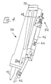
- the machine comprises a shoe support 10, for supporting, bottom down, the forepart of a shoe, a generally U-shaped so-called imprinter plate 12 which can be pressed against marginal portions of the forepart of an insole of a shoe supported by the shoe support 10 and thus cause adhesive to be applied to said marginal portions, together with a pincer assembly generally designated 14, a wiper assembly comprising two wiper plates 20, a toe band 22, a toe pad 24 and a heel rest generally designated 26.
- the machine also comprises a control panel 54 and a foot switch FS1.
- the apparatus in accordance with the invention comprises a side and heel seat lasting machine (Fig. 3) which is generally similar, except as hereinafter described, to the machine described in EP-A0050429.
- the machine comprises a shoe support 30 for supporting, bottom uppermost, a shoe for side and heel seat lasting operations to be performed thereon, said support being mounted for movement, fore-and-aft of the machine, between a loading position and the operating locality of the machine.
- the machine also comprises a holddown 32, a wiper assembly generally designated 34 for lasting heel seat portions of the shoe, and two side lasting assemblies generally designated 36 (one only shown in Fig. 3) for lasting side portions of the shoe.
- the machine comprises adhesive-applying means generally designated 38 (omitted from Fig. 3 but shown in Fig. 4) for applying adhesive to upstanding lasting marginal portions of the upper of a shoe supported by the shoe support 30 prior to the operation of the heel seat wiper assembly 34 and side lasting assemblies 36.
- each side lasting assembly comprises a plurality of lasting elements 140 in the form of lasting straps each of which is supported at its upper end by two fingers, independently pivoted about axes extending transversely of the shoe bottom, and each of which is backed by a pad 142; each assembly comprises four such lasting elements (Fig. 3).
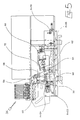
- the adhesive-applying means 38 is generally similar to the arrangement described in GB-A2118867 and comprises two nozzles 40 (Fig.
- the means 38 comprises a shoe bottom engaging member in the form of a skid 42 which is carried, for heightwise sliding movement in relation to the nozzles 40, by a piston rod 44 of a piston-and-cylinder arrangement 46 mounted on a bracket 48 itself carried by a support 50 for the nozzles 40.
- Means generally designated 52 is also provided for adjusting the heightwise movement of the skid in relation to the support 50, and thus in relation to the nozzles 40.
- the support 50 is itself supported on a carriage (not shown) which is movable by pneumatic motor means (not shown) fore-and-aft of the machine, thus to cause the nozzles 40 to track along opposite side portions of a shoe bottom as aforesaid.
- the heightwise position of the nozzles 40 is varied as they are caused to track along opposite marginal portions of the shoe upper as follows:
- the nozzles When applying adhesive to the heel seat portion of the shoe upper the lasting marginal portions have frequently been subjected to a previous backpart moulding and seat flanging operation and consequently tend to lie relatively flat and close to the insole.
- the nozzles In order to apply adhesive to this portion of the shoe upper, therefore, the nozzles have to be lowered in relation to the shoe bottom and this is achieved by retracting the skid 42 heightwise in relation to the nozzle support 50.
- the nozzles 40 Upon leaving the area which has been previously flanged as aforesaid, the nozzles 40 require to be raised, which is then achieved by lowering the skid 42 in relation to the nozzle support 50, and the nozzles are maintained at this height as they track along opposite side portions of the shoe toewardly along the waist region towards the ball region.
- each assembly is provided with its own stepping motor 66.
- two proximity switches PrS3, PrS4 associated with the output drive shaft of each stepping motor are two proximity switches PrS3, PrS4, constituting limit switches whereby the range of angular displacement of the assemblies 36 from the wiper plate is limited between 4° and 22°, as will be hereinafter referred to.
- the setting of the heel rest 26 of the pulling over and toe lasting machine is utilised for automatically setting up the various requirements of the side and heel seat lasting machine, in particular the angle at which the side lasting assemblies are inclined to the wiping plane of the heel seat wiper assembly 34, the length of trace, adhesive shut-off and also the incidence of the heightwise movement of the skid 42 relative to the nozzles 40.
- the heel rest 26 comprises a bracket 80 (Fig. 2) mounted on the machine frame and supporting a guide 82 extending heightwise of the machine, in which guide a block 84 is mounted for heightwise sliding movement, a clamp arrangement 86 being provided for locking the block in adjusted heightwise position.
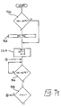
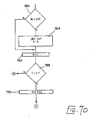
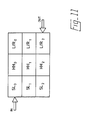
- step 302 interrogating the status of flag B. In general this will be set to a value one, which thereupon disables the foot switch FS2 until all the pre-setting of the machine is completed (step 304). If flag B equals zero, then step 304 is by-passed. At step 306 flag C is set to value zero and the software returns via junction F to step 250.
Landscapes
- Footwear And Its Accessory, Manufacturing Method And Apparatuses (AREA)
Applications Claiming Priority (2)
| Application Number | Priority Date | Filing Date | Title |
|---|---|---|---|
| GB8810109 | 1988-04-28 | ||
| GB888810109A GB8810109D0 (en) | 1988-04-28 | 1988-04-28 | Apparatus for lasting toe side & heel seat portions of shoe |
Publications (3)
| Publication Number | Publication Date |
|---|---|
| EP0339835A2 true EP0339835A2 (de) | 1989-11-02 |
| EP0339835A3 EP0339835A3 (de) | 1992-01-15 |
| EP0339835B1 EP0339835B1 (de) | 1995-02-15 |
Family
ID=10636054
Family Applications (1)
| Application Number | Title | Priority Date | Filing Date |
|---|---|---|---|
| EP89303658A Expired - Lifetime EP0339835B1 (de) | 1988-04-28 | 1989-04-13 | Schuh-Spitzen-, -Seiten- und -Fersenzwickmaschine |
Country Status (4)
| Country | Link |
|---|---|
| US (1) | US4920594A (de) |
| EP (1) | EP0339835B1 (de) |
| DE (1) | DE68921090D1 (de) |
| GB (1) | GB8810109D0 (de) |
Cited By (1)
| Publication number | Priority date | Publication date | Assignee | Title |
|---|---|---|---|---|
| WO1993018679A1 (en) * | 1992-03-25 | 1993-09-30 | Dvsg Engineering Und Patentverwaltungs Gmbh | Heel rest arrangement for a pulling over and lasting machine |
Families Citing this family (4)
| Publication number | Priority date | Publication date | Assignee | Title |
|---|---|---|---|---|
| GB9109271D0 (en) * | 1991-04-30 | 1991-06-19 | British United Shoe Machinery | Shoe support and machine for use in the manufacture of shoes |
| GB9109270D0 (en) * | 1991-04-30 | 1991-06-19 | British United Shoe Machinery | Machine for lasting side portions of shoe uppers |
| US5722103A (en) * | 1996-02-01 | 1998-03-03 | International Shoe Machine Corporation | Toe and side and heel lasting machine and method of lasting |
| TW201404326A (zh) * | 2013-09-30 | 2014-02-01 | kun-zhong Liu | 免縫鞋面的製造方法 |
Family Cites Families (10)
| Publication number | Priority date | Publication date | Assignee | Title |
|---|---|---|---|---|
| GB1600377A (en) * | 1977-04-16 | 1981-10-14 | British United Shoe Machinery | Shoe upper conforming machines |
| DE3169563D1 (en) * | 1980-10-16 | 1985-05-02 | British United Shoe Machinery | Machine for lasting side portions of shoe uppers |
| US4462132A (en) * | 1980-11-07 | 1984-07-31 | Usm Corporation | Shoe upper conforming machine |
| GB2118867B (en) * | 1982-04-28 | 1986-01-08 | British United Shoe Machinery | Machine for lasting side portions of shoes |
| US4470165A (en) * | 1982-07-29 | 1984-09-11 | International Shoe Machine Corporation | Toe lasting machine with adjustable heel clamp pad |
| GB8315953D0 (en) * | 1983-06-10 | 1983-07-13 | British United Shoe Machinery | Transfer apparatus |
| US4553281A (en) * | 1984-05-21 | 1985-11-19 | International Shoe Machine Corporation | Side and heel lasting machine |
| DE3530568C2 (de) * | 1985-08-27 | 1996-07-04 | Ver Schuhmasch Gmbh | Verfahren und Vorrichtung zum Ausgleich von Einspannfehlern von Schuhen, die in eine Schuhbearbeitungsmaschine eingesetzt sind |
| GB8606215D0 (en) * | 1986-03-13 | 1986-04-16 | Busm Co Ltd | Machine for shoe uppers |
| US4709433A (en) * | 1986-04-04 | 1987-12-01 | International Shoe Machine Corporation | Heel molder flanger |
-
1988
- 1988-04-28 GB GB888810109A patent/GB8810109D0/en active Pending
-
1989
- 1989-04-13 DE DE68921090T patent/DE68921090D1/de not_active Expired - Lifetime
- 1989-04-13 US US07/337,293 patent/US4920594A/en not_active Expired - Fee Related
- 1989-04-13 EP EP89303658A patent/EP0339835B1/de not_active Expired - Lifetime
Cited By (1)
| Publication number | Priority date | Publication date | Assignee | Title |
|---|---|---|---|---|
| WO1993018679A1 (en) * | 1992-03-25 | 1993-09-30 | Dvsg Engineering Und Patentverwaltungs Gmbh | Heel rest arrangement for a pulling over and lasting machine |
Also Published As
| Publication number | Publication date |
|---|---|
| US4920594A (en) | 1990-05-01 |
| GB8810109D0 (en) | 1988-06-02 |
| EP0339835B1 (de) | 1995-02-15 |
| EP0339835A3 (de) | 1992-01-15 |
| DE68921090D1 (de) | 1995-03-23 |
Similar Documents
| Publication | Publication Date | Title |
|---|---|---|
| EP0339835B1 (de) | Schuh-Spitzen-, -Seiten- und -Fersenzwickmaschine | |
| US5722103A (en) | Toe and side and heel lasting machine and method of lasting | |
| US5210897A (en) | Pulling over and toe lasting machines | |
| US4319373A (en) | Shoe lasting machine | |
| JPS58146306A (ja) | 工具の作動通路及び作動部分決定方法、これによる靴製造機、及びこれに用いるグリツド | |
| US5263216A (en) | Machine for lasting side and heel seat portions of shoes | |
| US4006504A (en) | Automatic heel and side lasting shoe machines | |
| US4404700A (en) | Machine for lasting side portions of shoes | |
| EP0210824B1 (de) | Fersenzwickmaschine | |
| EP0259431B1 (de) | Maschine zum überholen und zwicken des vorderteiles von schuhschäften | |
| EP0091321B1 (de) | Maschine zum fortschreitenden Aufrauhen der Randteile eines Schuhbodens | |
| EP0335566B1 (de) | Fersenform- und -zwickmaschine | |
| US5136745A (en) | Shoe support | |
| US4436771A (en) | Method of lasting shoes | |
| EP0511811B1 (de) | Maschine zum Herstellen von Schuhen | |
| US2608701A (en) | Platform laying and platform cover turning machine | |
| US5678269A (en) | Toe and side and heel lasting machine and method of lasting | |
| US4442563A (en) | Shoe lasting machine | |
| EP0379774B1 (de) | Bearbeitung der Seitenteile eines auf Leisten aufgespannten Schuhoberteiles | |
| US4377876A (en) | Shoe lasting machine | |
| EP0512863B1 (de) | Träger einer Sohlen- und Absatzeinheit | |
| EP0457882B1 (de) | Maschine zum aufzwicken der seitenteile von schuhoberteilen | |
| GB2091535A (en) | Automatically controlling shoe machinery as a lasted assembly is conveyed therethrough | |
| US5063629A (en) | Heel support device with reduced movement of support | |
| EP0756463A1 (de) | Maschine zum zwicken der seitenbereiche von schuhschäften |
Legal Events
| Date | Code | Title | Description |
|---|---|---|---|
| PUAI | Public reference made under article 153(3) epc to a published international application that has entered the european phase |
Free format text: ORIGINAL CODE: 0009012 |
|
| AK | Designated contracting states |
Kind code of ref document: A2 Designated state(s): DE GB IT |
|
| PUAL | Search report despatched |
Free format text: ORIGINAL CODE: 0009013 |
|
| AK | Designated contracting states |
Kind code of ref document: A3 Designated state(s): DE GB IT |
|
| 17P | Request for examination filed |
Effective date: 19920629 |
|
| 17Q | First examination report despatched |
Effective date: 19940429 |
|
| GRAA | (expected) grant |
Free format text: ORIGINAL CODE: 0009210 |
|
| AK | Designated contracting states |
Kind code of ref document: B1 Designated state(s): DE GB IT |
|
| PGFP | Annual fee paid to national office [announced via postgrant information from national office to epo] |
Ref country code: GB Payment date: 19950321 Year of fee payment: 7 |
|
| REF | Corresponds to: |
Ref document number: 68921090 Country of ref document: DE Date of ref document: 19950323 |
|
| ITF | It: translation for a ep patent filed | ||
| PG25 | Lapsed in a contracting state [announced via postgrant information from national office to epo] |
Ref country code: DE Effective date: 19950516 |
|
| PLBI | Opposition filed |
Free format text: ORIGINAL CODE: 0009260 |
|
| 26 | Opposition filed |
Opponent name: SCHOEN & CIE AG Effective date: 19951109 |
|
| PLBF | Reply of patent proprietor to notice(s) of opposition |
Free format text: ORIGINAL CODE: EPIDOS OBSO |
|
| PLBF | Reply of patent proprietor to notice(s) of opposition |
Free format text: ORIGINAL CODE: EPIDOS OBSO |
|
| PG25 | Lapsed in a contracting state [announced via postgrant information from national office to epo] |
Ref country code: GB Effective date: 19960413 |
|
| GBPC | Gb: european patent ceased through non-payment of renewal fee |
Effective date: 19960413 |
|
| PLBO | Opposition rejected |
Free format text: ORIGINAL CODE: EPIDOS REJO |
|
| PLBN | Opposition rejected |
Free format text: ORIGINAL CODE: 0009273 |
|
| STAA | Information on the status of an ep patent application or granted ep patent |
Free format text: STATUS: OPPOSITION REJECTED |
|
| 27O | Opposition rejected |
Effective date: 19980329 |
|
| PG25 | Lapsed in a contracting state [announced via postgrant information from national office to epo] |
Ref country code: IT Free format text: LAPSE BECAUSE OF NON-PAYMENT OF DUE FEES Effective date: 20050413 |