EP0339924A2 - Apparatus for the controlled generation and administration of ozone - Google Patents
Apparatus for the controlled generation and administration of ozone Download PDFInfo
- Publication number
- EP0339924A2 EP0339924A2 EP89304095A EP89304095A EP0339924A2 EP 0339924 A2 EP0339924 A2 EP 0339924A2 EP 89304095 A EP89304095 A EP 89304095A EP 89304095 A EP89304095 A EP 89304095A EP 0339924 A2 EP0339924 A2 EP 0339924A2
- Authority
- EP
- European Patent Office
- Prior art keywords
- ozone
- administration
- dosage
- blood
- monitor
- Prior art date
- Legal status (The legal status is an assumption and is not a legal conclusion. Google has not performed a legal analysis and makes no representation as to the accuracy of the status listed.)
- Granted
Links
Images

Classifications
-
- A—HUMAN NECESSITIES
- A61—MEDICAL OR VETERINARY SCIENCE; HYGIENE
- A61M—DEVICES FOR INTRODUCING MEDIA INTO, OR ONTO, THE BODY; DEVICES FOR TRANSDUCING BODY MEDIA OR FOR TAKING MEDIA FROM THE BODY; DEVICES FOR PRODUCING OR ENDING SLEEP OR STUPOR
- A61M1/00—Suction or pumping devices for medical purposes; Devices for carrying-off, for treatment of, or for carrying-over, body-liquids; Drainage systems
- A61M1/14—Dialysis systems; Artificial kidneys; Blood oxygenators ; Reciprocating systems for treatment of body fluids, e.g. single needle systems for hemofiltration or pheresis
- A61M1/16—Dialysis systems; Artificial kidneys; Blood oxygenators ; Reciprocating systems for treatment of body fluids, e.g. single needle systems for hemofiltration or pheresis with membranes
- A61M1/1698—Blood oxygenators with or without heat-exchangers
-
- A—HUMAN NECESSITIES
- A61—MEDICAL OR VETERINARY SCIENCE; HYGIENE
- A61M—DEVICES FOR INTRODUCING MEDIA INTO, OR ONTO, THE BODY; DEVICES FOR TRANSDUCING BODY MEDIA OR FOR TAKING MEDIA FROM THE BODY; DEVICES FOR PRODUCING OR ENDING SLEEP OR STUPOR
- A61M1/00—Suction or pumping devices for medical purposes; Devices for carrying-off, for treatment of, or for carrying-over, body-liquids; Drainage systems
- A61M1/14—Dialysis systems; Artificial kidneys; Blood oxygenators ; Reciprocating systems for treatment of body fluids, e.g. single needle systems for hemofiltration or pheresis
- A61M1/32—Oxygenators without membranes
-
- C—CHEMISTRY; METALLURGY
- C02—TREATMENT OF WATER, WASTE WATER, SEWAGE, OR SLUDGE
- C02F—TREATMENT OF WATER, WASTE WATER, SEWAGE, OR SLUDGE
- C02F1/00—Treatment of water, waste water, or sewage
- C02F1/72—Treatment of water, waste water, or sewage by oxidation
- C02F1/78—Treatment of water, waste water, or sewage by oxidation with ozone
-
- A—HUMAN NECESSITIES
- A61—MEDICAL OR VETERINARY SCIENCE; HYGIENE
- A61M—DEVICES FOR INTRODUCING MEDIA INTO, OR ONTO, THE BODY; DEVICES FOR TRANSDUCING BODY MEDIA OR FOR TAKING MEDIA FROM THE BODY; DEVICES FOR PRODUCING OR ENDING SLEEP OR STUPOR
- A61M2202/00—Special media to be introduced, removed or treated
- A61M2202/02—Gases
- A61M2202/0216—Ozone
-
- C—CHEMISTRY; METALLURGY
- C02—TREATMENT OF WATER, WASTE WATER, SEWAGE, OR SLUDGE
- C02F—TREATMENT OF WATER, WASTE WATER, SEWAGE, OR SLUDGE
- C02F1/00—Treatment of water, waste water, or sewage
- C02F1/008—Control or steering systems not provided for elsewhere in subclass C02F
-
- C—CHEMISTRY; METALLURGY
- C02—TREATMENT OF WATER, WASTE WATER, SEWAGE, OR SLUDGE
- C02F—TREATMENT OF WATER, WASTE WATER, SEWAGE, OR SLUDGE
- C02F2201/00—Apparatus for treatment of water, waste water or sewage
- C02F2201/78—Details relating to ozone treatment devices
- C02F2201/782—Ozone generators
Definitions
- This invention relates to apparatus for the controlled generation and administration of ozone.
- the treatment of patients with ozone is well known.
- the ozone can be used to treat viral and bacteriacidal infections and it is well known for ozone to be used in the treatment of a patient's blood and also to be used in the treatment of external sores and wounds.
- ozone When a patient's blood is being treated, this blood is normally removed from the patient, treated and then recirculated to the patient.
- the beneficial effects of ozone may be applied to both human and animal patients.
- this invention provides apparatus for the controlled generation and administration of ozone, which apparatus comprises generator means for generating ozone, monitor means for monitoring the ozone, dosage means for providing a correct amount of ozone for administration, and computer control means for controlling the operation of at least one of the generator means, the monitor means and the dosage means.
- the apparatus of the present invention can be used in a simple and easy manner by medical personnel in the treatment of patients.
- the apparatus may form complete medical treatment centre in which substantially all the apparatus that could be required for various modes of application of the ozone is provided in one single simple to operate unit.
- the generator means may comprise at least two cells. Each cell may have an electrode which is connected to at least one inverter. There may be three electrodes connected to three inverters. The or each inverter generates the power required for the ozone generation, for example high frequency, high voltage current. If desired, the generator means may comprise only one cell.
- the generator means may comprise inner and outer tubes.
- the inner tube may be plated with gold on its inner surface.
- Other electrically conductive materials may be used.
- the inner and the outer tubes are preferably made from glass, usually a silica glass.
- the generator means includes cooling means for cooling the generator means during operation of the apparatus.
- the cooling means may be a corrugated insert.
- the inner tube may contain the corrugated insert.
- the corrugated insert may extend the entire length of the inner tube.
- the corrugated insert may be made of copper or any other desired and appropriate material.
- the outer tube may have three separate gold plated bands on its outer surface, with each band constituting an electrode for connecting to a separate inverter. More or less than three bands and electrically conducting materials other than gold may be employed.
- the outer tube may be surrounded by a corrugated sleeve, for example made of copper.
- the inner tube may then form a common electrode for the outer electrodes formed by the bands on the outer tube.
- the inner and outer tubes may form an assembly which is dipped into a varnish which holds the various parts of the assembly together.
- the cooling means may include a fan positioned at each end of the inner and outer tubes.
- One fan may operate in a push mode whilst the other fan operates in a pull mode.
- the insert in the inner tube helps the air from the fans to take any heat away.
- the monitor means may monitor the amount of ozone generated by the generator means and/or administered.
- the monitor means comprises an ultra violet light source and a photocell detector.
- Other light sources and other light detectors may be used so that, for example, the photocell detector may be replaced by a strobed detector.
- the strobed detector may be strobed by a zeon light source.
- the dosage means is able automatically to provide the correct amount of ozone in dependence upon information fed to the dosage means.
- the dosage means may be able to control volume delivery of the ozone in relation to the ozone discharge time.
- the apparatus of the present invention may include selector means for providing the generated ozone for a chosen one of a plurality of methods of administration.
- the selector means may comprise a valve unit for directing the ozone to at least one of blood purging apparatus for the treatment of a patient's blood, a constant flow container for large area external administration, and a cup device for small area external administration.
- the apparatus of the invention may include pump means for enabling an operator to dial the volume of ozone to be delivered.
- the pump means may be a peristaltic pump or a twin piston valveless pump.
- the apparatus of the invention may include ozone destructor means.
- the apparatus of the invention may also include a purge device and blood container for use in the treatment of the patient's blood, a constant flow bag/boot for use in the large area external administration, and a cup device for use in the small area external administration.
- apparatus 2 for the controlled generation and administration of ozone.
- the apparatus 2 comprises generator means 4 for generating ozone, monitor means 6 for monitoring the amount of ozone generated by the generator means 4, and dosage means 8 for providing a correct amount of ozone for administration to a patient.
- the apparatus 2 further comprises computer control means which may be housed inside the dosage means 8 and which is for controlling the operation of the generator means 4, the monitor means 6 and the dosage means 8.
- the generator means 4 has three separate cells and each of these cells is connected to three separate inverters 10,12,14 via a TFMR.
- the generator means 4 comprises an inner tube 16 and an outer tube 18.
- the inner tube 16 is plated with gold on its inner surface 20.
- the inner and the outer tubes 16,18 are made from silica glass.
- the inner tube 16 contains a corrugated insert 22 which is made of copper and which extends the entire length of the inner tube.
- the outer tube 18 has three separate gold plated bands (not shown) along its outer surface 24. Each of these bands constitutes one of the three electrodes for connection to one of the three inverters 10,12,14.
- the outer tube 18 is surrounded by a corrugated sleeve 26 which is made of copper.
- the generator means 4 is provided with a fan 28 at one end and with a fan 30 at the other end.
- the fan 28 operates in a push mode, whilst the fan 30 operates in a pull mode.
- a good flow of air passes through the generator means 4 with the insert 22 helping to disperse the air and help the air to take away any heat that is generated.
- the copper of the insert 22 also makes electrical contact with the gold plating.
- the monitor means 6 comprises an ultra violet light source (not shown) and a strobed detector (not shown).
- the detector is strobed by a zeon light source but it may be strobed by another light source if desired.
- the dosage means 8 is able automatically to provide the correct amount of ozone in dependence upon information fed to the dosage means.
- the dosage means 8 controls the volume delivery in cubic centimetres in relation to the ozone discharge time.
- the dosage means 8 has a button 32 for initiating an automatic dosage, a button 34 for initiating a purge sequence, a button 36 for initiating a set mode, and a button 38 for initiating a deliver mode.
- the dosage means 8 has a control knob 40 for varying oxygen flow, and a control knob 42 for varying the vacuum.
- the dosage means 8 has a mode control knob 44 and a high voltage knob 46.
- the dosage means 8 further has a control knob 48 for controlling volts required, these volts being shown in a panel 50.
- a similar control knob 52 enables the percentage of oxygen dialled to be shown in a panel 54.
- the apparatus 2 includes selector means 56 for providing the generated ozone for a chosen one of a plurality of methods of administration.
- the selector means 56 comprises a valve unit for directing the ozone along conduit 58 to blood purging apparatus 60 for the treatment of a patient's blood, along conduit 62 to a constant flow container 64 for large area external administration, or along conduit 66 to a cup device 68 for small area external administration.
- the constant flow container 64 may be a bag or a boot.
- the apparatus 2 includes pump means in the form of a peristaltic pump 70 which enables an operator to dial the volume of ozone to be delivered.
- the pump means is in effect a vacuum pump.
- the apparatus 2 includes ozone destructor means 72.
- the ozone passes along conduit 58 to an automatically regulated dose syringe 74 which is connected by conduit 76 and a connector 78 to the purging apparatus 60.
- the purging apparatus 60 comprises a device 80 which receives oxygen and ozone from the syringe 74 via conduit 76 and connector 78.
- the oxygen and ozone pass through a flask 82 containing the blood to be treated with the ozone.
- Oxygen and ozone from the flask 82 are then recycled via line 83 and connector 88 to the destructor means 72.
- Oxygen is vented to atmosphere through an oxygen outlet 90.
- the syringe 74 is connected by a conduit 84 to the destructor means 72 so that excess ozone can be destroyed.
- the apparatus 2 may be provided in a housing 26 provided with appropriate connectors 78, 92, 94, 96, 98, 100.
- an oxygen supply cylinder 102 is connected via an external pressure regulator 104 to the connector 100.
- a solenoid 106 is connected to the connector 102.
- the oxygen can thus pass through the external regulator 104 and the solenoid 106 to a filter 108 and then to an internal variable flow valve 110.
- the variable flow valve 110 is connected as shown to a flow gauge 112 which connects by conduit 114 to the generator means 4.
- the generator means 4 is controlably provided with oxygen for conversion into ozone.
- the conversion of the oxygen into the ozone is via an appropriate electrical discharge to be effected between the inner tube 16 and the outer tube 18, and more specifically between the electrodes thereof.
- the discharge is preferably a plasma discharge.
- the discharge is provided via a mains input 116 which feeds a power supply unit 118 and which in turn feeds the inverters 10,12,14.
- the generated ozone is monitored by the monitor means 6 and the monitor means 6 is connected to the dosage means 8 by a negative feedback loop 120.
- the housing 96 is also provided with an input drive 122 to control the input into the generator means 4.
- the cup device 68 is connected to the pump means 70 by means of a filter 124.
- a variable vacuum valve 126 connects the pump means 70 to the destructor means 72.
- the selector means 156 is able to divert the generated ozone for either one of the three available modes of use or, alternatively, to divert the apparatus into its negative feedback loop mode of use.
- FIG. 2 there is shown how some of the components shown in Figure 1 may be mounted on a base chassis 128.
- the base chassis may be 600mm long and 500mm wide.
- the power supply unit 118 as shown in Figure 2 may be variably driven by the input drive 122 (which is not shown in Figure 2).
- Figure 2 also shows positioned on the base chassis 128 a printed circuit board sensor 130 for use with the monitor means 6. Also shown is a printed circuit board 132 for use with a relay output, and a 15 volt regulator 134 for the power supply unit 118.
- the computer control means may be effective to provide a hard copy readout of various operating perameters so that a physician does not have to rely solely on information shown on a screen.
- the illustrated external pressure regulator 104 may be a regulating valve on the oxygen cylinder 102.
- the use of the extra regulator in the form of the solenoid 106 is to provide a safety feature in case the external pressure regulator 104 should become damaged during transit and supply to a hospital or medical treatment centre using the apparatus 2.
- the flow gauge 112 enables an operator to see what flow has been dialled on the variable flow valve 110.
- the flow gauge 112 may show a flow rate from 0-10 litres per minute.
- the monitor means 6 preferably measures the concentration of ozone in micrograms per cubic centimetre in relation to the oxygen present.
- the use of the feed back loop 120 enables the electrical input to the apparatus 2 automatically to be reduced if the monitor means 6 senses that too much ozone is being produced. Similarly, if the monitor means 6 senses than an insufficient amount of ozone is being produced, then the electrical power input into the apparatus 2 can be appropriately increased to give the required amount of generated ozone.
- the apparatus 2 thus has in effect an ozone constant flow meter.
- the apparatus 2 can also be used in other applications for which ozone is known to be useful, for example in the purification of water.
- the ozone that is generated can be measured as a percentage by weight, a percentage by volume, or as is preferred, as micrograms per cubic centimetre.
- the use of pure silica glass tubes for the inner and outer tubes 16,18 is preferred since the apparatus 2 can then work at 185 nanometer wavelength of the ultra violet spectrum range.
- the silica tubes reflect the ultra violet wavelength back into the cells, thus reducing any spurious loss of the ultra violet light generated by the corona discharge occuring between the electrodes in the generator means 4.
- the generator means 4 is also chosen to be of a size that gives the correct and required type of ozone generation without degradation of the ozone occuring between 0 and 10 metres per minute of ozone generation.
- the generator means 4 is also designed to minimise on any stalling of the oxygen and the ozone as they pass through the generator means 4, since this stalling will in itself result in a rapid degradation of the ozone.
- the apparatus 2 can be arranged to operate on 110 or 220 volts ac.
- the power supply unit 118 is effective to convert the alternating current from the mains to a variable 7-15 volts dc output.
- the apparatus 2 will usually be completely purged to ensure that the apparatus 2 contains the ozone at the required concentration. This purging can be effected by an appropriate selection on the selector means 56.
- the control of the discharge rates is achieved because the internal syringe 74 is driven by an electrical magnetic impulse motor in the form of a stepper motor. Because the stepper motor will only operate on the number of pulses received, the stepper motor is easily able to control the travel of charge and discharge of the syringe 74.
- an infra red chopper sensor may be employed to calculate very accurately the amount of ozone delivered.
- the amount of the ozone to be delivered can be automatically dialled, for example in cubic centimetres. It will then only be necessary to press a start button and the delivery will commence at a desired flow rate and concentration. The discharge rate can be altered by varying the speed of the pump motor.
- the destructor means 72 used in the apparatus 2 may be any ozone destructor means. Such ozone destructor means are already available.
- purging is preferably effected first with oxygen and then with the required concentration of the ozone.
- the apparatus 2 can be made to be portable or static. In either mode of construction, the apparatus 2 can be simply used by medical personnel to provide in one medical treatment centre the facility to treat patients in a variety of ways.
- FIG. 5 there is shown second apparatus for the controlled generation and administration of ozone. Similar parts as in the previous drawings have been given the same reference numbers for ease of comparison and understanding.
- the monitors 6A and 6B in the apparatus 2 are in line. This means that the monitors 6A and 6B are such that the generated gas passes through the monitors as shown. The measured gas also passes into a hollow fibre device 75 as shown.
- the monitors measure the concentration of the ozone in the oxygen and ozone gas mixture constantly. The readout can be averaged over a short period of time to minimise readout fluctuations.
- the sensivitity of reading of the monitors is divided into two scales, being 0 - 10 ⁇ g per cc, and 10 - 100 ⁇ g per cc.
- the divisions on the first scale may be 0.1 ⁇ g.
- the divisions on the second scale may be 1.0 ⁇ g. Both readouts should be accurate to ⁇ 1% of true value.
- the measurement of the ozone in the gas flow is computer linked via the computer control 77 to the generation of gas in order to ensure a constant level of production (concentration).
- the flow rate of the produced gas is variable from 0-5 litres per minute, adjustable by increments of 0.1 litres per minute.
- the apparatus 2 is able to establish the maximum and minimum ozone production possible at the varying rates of gas flow.
- the apparatus 2 enables an operator to know the amount of ozone that is used in the treatment of blood or other product. This will be the amount prescribed by physicians. This amount is the difference between the gas delivered to the hollow fibre device 75 and the amount exhausted and is thus the value at monitor 6A minus the value at monitor 6B.
- the input monitor 6A and the exhaust monitor 6B are linked via the computer control 77 in real time to ensure a value of reactive gas used.
- the ozone generator 4 is supplied with an initial source of oxygen for the generation of the ozone. Blood from a pump and a reservoir passes as shown to the hollow fibre device 75. Blood from the hollow fibre device with the ozone is circulated back to the pump and reservoir (not shown).
- the ozone generator means 4, the monitor 6A, the monitor 6B, the volume dosage means 8, the computer control 77 and the destructor 72 form internal parts of the apparatus 2.
- the hollow fibre device 75 which is in fact a hollow fibre is used for transferring the gas to the substance such for example as blood to be exposed to chemical action.
- the hollow fibre device 75 may be replaced by any other suitable and appropriate device for transferring the oxygen and ozone mixture to the substance to be treated.
- the apparatus 2 can be designed differently, especially if it is to be used for the generation of ozone in the treatment of water or other products which do not involve the treatment of patients.
- Three different input sockets 116 may be provided for the operation of the apparatus 2 on 220 volts, 110 volts and 12 volts.
- the apparatus 2 can be arranged to operate on a.c. or d.c. from mains and/or battery as may be desired.
- the constant flow container 64, the cup device 68 and the gas injector device 80 are given as examples of the type of equipment that may be connected to the main body of the apparatus 2 of the invention.
- a loop connection from the connector 78 and the device 80 could enable ozone to be drawn off into a hypordermic syringe.
- the apparatus of the invention lends itself well to computerisation.
- the apparatus of the invention may be regarded as comprising generator means for generating ozone, in line monitor means, dosage means for giving for example volume control, and electronic integrated control means.
- the dosage means may be such as to dispense a volume of gas, for example on a time or pump basis. This is because an operator of the apparatus may need to know how much of the ozone is delivered in useable form for example how much of the ozone is taken up in a chemical reaction.
- the gas ie the oxygen with the required amount of ozone
- the dosage means for example a dosimeter
- the gas is normally passed through a device for applying the gas to the required products, for example human blood.
- the monitor means may be positioned on the exhaust side of the device for applying the gas.
- the correct amount of the ozone has been generated, this does not necessarily mean that the correct amount of the ozone will be used. It may therefore be desirable to measure the gas going in and the gas going out. The difference between the two measurements will give the amount of ozone being used.
- a single monitor may be used to measure the gas going in and the gas coming out.
- two monitors may be used.
- the monitor or monitors may be linked to the computer means and the apparatus may be arranged to keep producing ozone until the required amount of ozone is used in the required chemical reaction.
- the apparatus may thus deliver ozone on a continuous basis until the difference between the gas going in and the gas coming out shows that the required amount of ozone has been taken up in the product being treated by the required predetermined amount.
- the ozone may be produced on a continuous basis.
- the monitor means may be an absorption meter. One or two monitors may be used to measure the dose of the ozone absorbed, as opposed to measuring the flow of the ozone.
- the generator means for generating the ozone may comprise a single inverter.
- the single inverter may have three coils. Basically, each cell for the generator means may comprise an electrode and a dielectric for dispersing an electrical discharge.
- the apparatus of the invention may be regarded as apparatus that produces a precise amount of ozone and oxygen and which forms an enclosed delivery system from the gas production to the gas use.
- the apparatus may be regarded as essentially comprising the generator means for generating the ozone, and the monitor means which may be an in line monitor that measures the concentration of the ozone in the mixture of air and ozone being produced.
- the apparatus may also include the dosage means which may be in the form of a dosimeter which delivers a fixed volume of a mixture of oxygen and ozone with the oxygen being a carrier gas for the ozone.
- the dosage means may be a syringe or a timer on a fixed flow device.
- the dosage means may also be means for allowing the mixture of oxygen and ozone to keep flowing until the apparatus calculates that the required or original amount of ozone has been used in the reaction.
- the mixture of the ozone and oxygen may flow into a reaction chamber which is external to the apparatus and which thus does not form a part of the apparatus.
- the mixture may flow in a constant flow mode, for a set time or as a predetermined volume of gas.
- the mixture of ozone and oxygen is continuously kept flowing until it is calculated that the required amount of ozone has been used in a desired reaction.
- the exhaust gases coming out of the reaction chamber may be taken back into a monitor which measures the ozone content of the exhaust gas.
- the apparatus may keep working until the original amount of ozone keyed in by an operator has been used in the reaction.
- the calculations required may be done by a micro-processor.
- the product to be treated may be in the external chamber.
- the product to be treated with the required chemical reaction may be mammalian blood, other blood components and cell structures.
- the ozone may also be used to treat products other than blood so that the apparatus of the invention may be used to purify water with the ozone being passed through the water and being stopped, for example, when a certain predetermined keyed in amount of microgrammes of the ozone have been used up.
- the mixture of oxygen and ozone gas entering and exhausting from the product is preferably measured with the difference between the measurements indicating the amount of ozone absorbed in the required reaction.
Landscapes
- Health & Medical Sciences (AREA)
- Emergency Medicine (AREA)
- Heart & Thoracic Surgery (AREA)
- Life Sciences & Earth Sciences (AREA)
- Urology & Nephrology (AREA)
- Engineering & Computer Science (AREA)
- Public Health (AREA)
- Biomedical Technology (AREA)
- Hematology (AREA)
- Anesthesiology (AREA)
- Animal Behavior & Ethology (AREA)
- General Health & Medical Sciences (AREA)
- Vascular Medicine (AREA)
- Veterinary Medicine (AREA)
- Environmental & Geological Engineering (AREA)
- Hydrology & Water Resources (AREA)
- Water Supply & Treatment (AREA)
- Chemical & Material Sciences (AREA)
- Organic Chemistry (AREA)
- Oxygen, Ozone, And Oxides In General (AREA)
- Infusion, Injection, And Reservoir Apparatuses (AREA)
- External Artificial Organs (AREA)
- Apparatus For Disinfection Or Sterilisation (AREA)
- Medicines Containing Plant Substances (AREA)
- Treatment Of Water By Oxidation Or Reduction (AREA)
Abstract
Description
- This invention relates to apparatus for the controlled generation and administration of ozone.
- The treatment of patients with ozone is well known. The ozone can be used to treat viral and bacteriacidal infections and it is well known for ozone to be used in the treatment of a patient's blood and also to be used in the treatment of external sores and wounds. When a patient's blood is being treated, this blood is normally removed from the patient, treated and then recirculated to the patient. The beneficial effects of ozone may be applied to both human and animal patients.
- Although the treatment of patients with ozone is well known and although the beneficial healing effects of ozone has been proved and well documented, problems often arise in the provision of suitable apparatus for the treatment of a patient with the ozone. Much of the existing apparatus involves outdated technology and the existing apparatus cannot easily and conveniently be used by medical personnel in the treatment of patients.
- It is an aim of the present invention to obviate or reduce the above mentioned problem.
- Accordingly, this invention provides apparatus for the controlled generation and administration of ozone, which apparatus comprises generator means for generating ozone, monitor means for monitoring the ozone, dosage means for providing a correct amount of ozone for administration, and computer control means for controlling the operation of at least one of the generator means, the monitor means and the dosage means.
- The apparatus of the present invention can be used in a simple and easy manner by medical personnel in the treatment of patients. The apparatus may form complete medical treatment centre in which substantially all the apparatus that could be required for various modes of application of the ozone is provided in one single simple to operate unit.
- The generator means may comprise at least two cells. Each cell may have an electrode which is connected to at least one inverter. There may be three electrodes connected to three inverters. The or each inverter generates the power required for the ozone generation, for example high frequency, high voltage current. If desired, the generator means may comprise only one cell.
- The generator means may comprise inner and outer tubes. The inner tube may be plated with gold on its inner surface. Other electrically conductive materials may be used. The inner and the outer tubes are preferably made from glass, usually a silica glass.
- Preferably, the generator means includes cooling means for cooling the generator means during operation of the apparatus. The cooling means may be a corrugated insert.
- When the generator means includes inner and outer tubes, the inner tube may contain the corrugated insert. The corrugated insert may extend the entire length of the inner tube. The corrugated insert may be made of copper or any other desired and appropriate material.
- The outer tube may have three separate gold plated bands on its outer surface, with each band constituting an electrode for connecting to a separate inverter. More or less than three bands and electrically conducting materials other than gold may be employed. The outer tube may be surrounded by a corrugated sleeve, for example made of copper. The inner tube may then form a common electrode for the outer electrodes formed by the bands on the outer tube.
- The inner and outer tubes may form an assembly which is dipped into a varnish which holds the various parts of the assembly together.
- The cooling means may include a fan positioned at each end of the inner and outer tubes. One fan may operate in a push mode whilst the other fan operates in a pull mode. With such an arrangement, the insert in the inner tube helps the air from the fans to take any heat away.
- The monitor means may monitor the amount of ozone generated by the generator means and/or administered.
- Preferably, the monitor means comprises an ultra violet light source and a photocell detector. Other light sources and other light detectors may be used so that, for example, the photocell detector may be replaced by a strobed detector. The strobed detector may be strobed by a zeon light source.
- Preferably, the dosage means is able automatically to provide the correct amount of ozone in dependence upon information fed to the dosage means. The dosage means may be able to control volume delivery of the ozone in relation to the ozone discharge time.
- The apparatus of the present invention may include selector means for providing the generated ozone for a chosen one of a plurality of methods of administration.
- The selector means may comprise a valve unit for directing the ozone to at least one of blood purging apparatus for the treatment of a patient's blood, a constant flow container for large area external administration, and a cup device for small area external administration.
- The apparatus of the invention may include pump means for enabling an operator to dial the volume of ozone to be delivered. The pump means may be a peristaltic pump or a twin piston valveless pump.
- The apparatus of the invention may include ozone destructor means.
- The apparatus of the invention may also include a purge device and blood container for use in the treatment of the patient's blood, a constant flow bag/boot for use in the large area external administration, and a cup device for use in the small area external administration.
- Embodiments of the invention will now be described solely by way of example and with reference to the accompanying drawings in which:
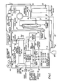
- Figure 1 shows a layout of first apparatus for the controlled generation and administration of ozone;
- Figure 2 shows how parts of the apparatus shown in Figure 1 may be mounted on a base chassis;
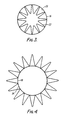
- Figure 3 is an end view of an inner tube forming part of generator means for generating ozone;
- Figure 4 is an end view of an outer tube forming part of the generator means for generating ozone; and
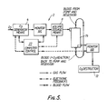
- Figure 5 shows second apparatus for the controlled generation and administration of ozone.
- Referring to Figures 1 to 4, there is shown
apparatus 2 for the controlled generation and administration of ozone. Theapparatus 2 comprises generator means 4 for generating ozone, monitor means 6 for monitoring the amount of ozone generated by the generator means 4, and dosage means 8 for providing a correct amount of ozone for administration to a patient. Theapparatus 2 further comprises computer control means which may be housed inside the dosage means 8 and which is for controlling the operation of the generator means 4, the monitor means 6 and the dosage means 8. - The generator means 4 has three separate cells and each of these cells is connected to three
separate inverters - As shown in Figures 3 and 4, the generator means 4 comprises an
inner tube 16 and anouter tube 18. Theinner tube 16 is plated with gold on itsinner surface 20. The inner and theouter tubes inner tube 16 contains acorrugated insert 22 which is made of copper and which extends the entire length of the inner tube. Theouter tube 18 has three separate gold plated bands (not shown) along itsouter surface 24. Each of these bands constitutes one of the three electrodes for connection to one of the threeinverters outer tube 18 is surrounded by a corrugated sleeve 26 which is made of copper. When theinner tube 16 is positioned inside theouter tube 18, the entire assembly is dipped into a varnish to hold the various parts of the assembly together. The assembly then has a common electrode formed by the inner tube and three outer electrodes which are formed by the three gold plated bands and which are for connection to the threeinverters - As shown in Figure 1, the generator means 4 is provided with a
fan 28 at one end and with afan 30 at the other end. Thefan 28 operates in a push mode, whilst thefan 30 operates in a pull mode. Thus a good flow of air passes through the generator means 4 with theinsert 22 helping to disperse the air and help the air to take away any heat that is generated. The copper of theinsert 22 also makes electrical contact with the gold plating. - The monitor means 6 comprises an ultra violet light source (not shown) and a strobed detector (not shown). The detector is strobed by a zeon light source but it may be strobed by another light source if desired.
- The dosage means 8 is able automatically to provide the correct amount of ozone in dependence upon information fed to the dosage means. The dosage means 8 controls the volume delivery in cubic centimetres in relation to the ozone discharge time. As can be seen from Figure 1, the dosage means 8 has a button 32 for initiating an automatic dosage, a button 34 for initiating a purge sequence, a button 36 for initiating a set mode, and a button 38 for initiating a deliver mode. In addition, the dosage means 8 has a
control knob 40 for varying oxygen flow, and acontrol knob 42 for varying the vacuum. Additionally, the dosage means 8 has a mode control knob 44 and a high voltage knob 46. - The dosage means 8 further has a
control knob 48 for controlling volts required, these volts being shown in apanel 50. Asimilar control knob 52 enables the percentage of oxygen dialled to be shown in apanel 54. - The
apparatus 2 includes selector means 56 for providing the generated ozone for a chosen one of a plurality of methods of administration. The selector means 56 comprises a valve unit for directing the ozone alongconduit 58 toblood purging apparatus 60 for the treatment of a patient's blood, alongconduit 62 to aconstant flow container 64 for large area external administration, or alongconduit 66 to acup device 68 for small area external administration. Theconstant flow container 64 may be a bag or a boot. - The
apparatus 2 includes pump means in the form of aperistaltic pump 70 which enables an operator to dial the volume of ozone to be delivered. The pump means is in effect a vacuum pump. - The
apparatus 2 includes ozone destructor means 72. - When the
apparatus 2 is used in the blood purging mode, then the ozone passes alongconduit 58 to an automaticallyregulated dose syringe 74 which is connected byconduit 76 and aconnector 78 to thepurging apparatus 60. The purgingapparatus 60 comprises adevice 80 which receives oxygen and ozone from thesyringe 74 viaconduit 76 andconnector 78. The oxygen and ozone pass through aflask 82 containing the blood to be treated with the ozone. Oxygen and ozone from theflask 82 are then recycled vialine 83 andconnector 88 to the destructor means 72. Oxygen is vented to atmosphere through anoxygen outlet 90. Thesyringe 74 is connected by aconduit 84 to the destructor means 72 so that excess ozone can be destroyed. - The
apparatus 2 may be provided in a housing 26 provided withappropriate connectors - As shown in Figure 1, an
oxygen supply cylinder 102 is connected via anexternal pressure regulator 104 to theconnector 100. Inside the housing 86, asolenoid 106 is connected to theconnector 102. The oxygen can thus pass through theexternal regulator 104 and thesolenoid 106 to afilter 108 and then to an internalvariable flow valve 110. Thevariable flow valve 110 is connected as shown to aflow gauge 112 which connects byconduit 114 to the generator means 4. Thus the generator means 4 is controlably provided with oxygen for conversion into ozone. - The conversion of the oxygen into the ozone is via an appropriate electrical discharge to be effected between the
inner tube 16 and theouter tube 18, and more specifically between the electrodes thereof. The discharge is preferably a plasma discharge. The discharge is provided via amains input 116 which feeds apower supply unit 118 and which in turn feeds theinverters negative feedback loop 120. - The
housing 96 is also provided with aninput drive 122 to control the input into the generator means 4. - The
cup device 68 is connected to the pump means 70 by means of afilter 124. Avariable vacuum valve 126 connects the pump means 70 to the destructor means 72. - During operation of the
apparatus 2, the selector means 156 is able to divert the generated ozone for either one of the three available modes of use or, alternatively, to divert the apparatus into its negative feedback loop mode of use. - Referring now to Figure 2, there is shown how some of the components shown in Figure 1 may be mounted on a
base chassis 128. As shown in Figure 2, the base chassis may be 600mm long and 500mm wide. Thepower supply unit 118 as shown in Figure 2 may be variably driven by the input drive 122 (which is not shown in Figure 2). Figure 2 also shows positioned on the base chassis 128 a printedcircuit board sensor 130 for use with the monitor means 6. Also shown is a printedcircuit board 132 for use with a relay output, and a 15volt regulator 134 for thepower supply unit 118. - The computer control means may be effective to provide a hard copy readout of various operating perameters so that a physician does not have to rely solely on information shown on a screen.
- The illustrated
external pressure regulator 104 may be a regulating valve on theoxygen cylinder 102. The use of the extra regulator in the form of thesolenoid 106 is to provide a safety feature in case theexternal pressure regulator 104 should become damaged during transit and supply to a hospital or medical treatment centre using theapparatus 2. Theflow gauge 112 enables an operator to see what flow has been dialled on thevariable flow valve 110. Theflow gauge 112 may show a flow rate from 0-10 litres per minute. - The monitor means 6 preferably measures the concentration of ozone in micrograms per cubic centimetre in relation to the oxygen present. The use of the feed back
loop 120 enables the electrical input to theapparatus 2 automatically to be reduced if the monitor means 6 senses that too much ozone is being produced. Similarly, if the monitor means 6 senses than an insufficient amount of ozone is being produced, then the electrical power input into theapparatus 2 can be appropriately increased to give the required amount of generated ozone. Theapparatus 2 thus has in effect an ozone constant flow meter. - In addition to the uses of the
apparatus 2 as a medical treatment centre, theapparatus 2 can also be used in other applications for which ozone is known to be useful, for example in the purification of water. - The ozone that is generated can be measured as a percentage by weight, a percentage by volume, or as is preferred, as micrograms per cubic centimetre. The use of pure silica glass tubes for the inner and
outer tubes apparatus 2 can then work at 185 nanometer wavelength of the ultra violet spectrum range. The silica tubes reflect the ultra violet wavelength back into the cells, thus reducing any spurious loss of the ultra violet light generated by the corona discharge occuring between the electrodes in the generator means 4. The generator means 4 is also chosen to be of a size that gives the correct and required type of ozone generation without degradation of the ozone occuring between 0 and 10 metres per minute of ozone generation. - The generator means 4 is also designed to minimise on any stalling of the oxygen and the ozone as they pass through the generator means 4, since this stalling will in itself result in a rapid degradation of the ozone.
- Driving of the generator means 4 by the three
separate inverters - The
apparatus 2 can be arranged to operate on 110 or 220 volts ac. Thepower supply unit 118 is effective to convert the alternating current from the mains to a variable 7-15 volts dc output. - During start up of the
apparatus 2, theapparatus 2 will usually be completely purged to ensure that theapparatus 2 contains the ozone at the required concentration. This purging can be effected by an appropriate selection on the selector means 56. - Existing apparatus that is known to produce ozone for the treatment of patients tends to cause stalling of oxygen and ozone within the apparatus which is undesirable, for example in causing premature degradation of the ozone. Also, the known apparatus gives little or no control of the discharge of a sample from a syringe equivalent to the
syringe 74. In theapparatus 2 of the present invention, the stalling of oxygen and ozone is substantially avoided and good control is achieved over the discharge of a sample from the syringe74. The stalling of the oxygen and the ozone in theapparatus 2 of the present invention is avoided due to the fact that electrically operated drawing off means is employed. Similarly, the control of the discharge rates is achieved because theinternal syringe 74 is driven by an electrical magnetic impulse motor in the form of a stepper motor. Because the stepper motor will only operate on the number of pulses received, the stepper motor is easily able to control the travel of charge and discharge of thesyringe 74. - When the
apparatus 2 is used employing theconstant flow container 64, an infra red chopper sensor may be employed to calculate very accurately the amount of ozone delivered. Where it is desired to use the peristaltic pump means 70, the amount of the ozone to be delivered can be automatically dialled, for example in cubic centimetres. It will then only be necessary to press a start button and the delivery will commence at a desired flow rate and concentration. The discharge rate can be altered by varying the speed of the pump motor. - The destructor means 72 used in the
apparatus 2 may be any ozone destructor means. Such ozone destructor means are already available. - During use of the
apparatus 2, purging is preferably effected first with oxygen and then with the required concentration of the ozone. - The
apparatus 2 can be made to be portable or static. In either mode of construction, theapparatus 2 can be simply used by medical personnel to provide in one medical treatment centre the facility to treat patients in a variety of ways. - Referring now to Figure 5, there is shown second apparatus for the controlled generation and administration of ozone. Similar parts as in the previous drawings have been given the same reference numbers for ease of comparison and understanding. In Figure 5, there are two monitors, 6A and 6B. The
monitors apparatus 2 are in line. This means that themonitors hollow fibre device 75 as shown. The monitors measure the concentration of the ozone in the oxygen and ozone gas mixture constantly. The readout can be averaged over a short period of time to minimise readout fluctuations. Advantageously, the sensivitity of reading of the monitors is divided into two scales, being 0 - 10µg per cc, and 10 - 100 µg per cc. The divisions on the first scale may be 0.1 µg. The divisions on the second scale may be 1.0 µg. Both readouts should be accurate to ± 1% of true value. - The measurement of the ozone in the gas flow is computer linked via the
computer control 77 to the generation of gas in order to ensure a constant level of production (concentration). The flow rate of the produced gas is variable from 0-5 litres per minute, adjustable by increments of 0.1 litres per minute. - The
apparatus 2 is able to establish the maximum and minimum ozone production possible at the varying rates of gas flow. Theapparatus 2 enables an operator to know the amount of ozone that is used in the treatment of blood or other product. This will be the amount prescribed by physicians. This amount is the difference between the gas delivered to thehollow fibre device 75 and the amount exhausted and is thus the value atmonitor 6A minus the value atmonitor 6B. Theinput monitor 6A and theexhaust monitor 6B are linked via thecomputer control 77 in real time to ensure a value of reactive gas used. - The
ozone generator 4 is supplied with an initial source of oxygen for the generation of the ozone. Blood from a pump and a reservoir passes as shown to thehollow fibre device 75. Blood from the hollow fibre device with the ozone is circulated back to the pump and reservoir (not shown). - The ozone generator means 4, the
monitor 6A, themonitor 6B, the volume dosage means 8, thecomputer control 77 and thedestructor 72 form internal parts of theapparatus 2. Thehollow fibre device 75 which is in fact a hollow fibre is used for transferring the gas to the substance such for example as blood to be exposed to chemical action. Thehollow fibre device 75 may be replaced by any other suitable and appropriate device for transferring the oxygen and ozone mixture to the substance to be treated. - It is to be appreciated that the embodiments of the invention described above with reference to the accompanying drawings have been given by way of example only and that modifications may be effected. Thus, for example, the
apparatus 2 can be designed differently, especially if it is to be used for the generation of ozone in the treatment of water or other products which do not involve the treatment of patients. Threedifferent input sockets 116 may be provided for the operation of theapparatus 2 on 220 volts, 110 volts and 12 volts. Theapparatus 2 can be arranged to operate on a.c. or d.c. from mains and/or battery as may be desired. Theconstant flow container 64, thecup device 68 and thegas injector device 80 are given as examples of the type of equipment that may be connected to the main body of theapparatus 2 of the invention. Thus a loop connection from theconnector 78 and thedevice 80 could enable ozone to be drawn off into a hypordermic syringe. - Various different cell structures for the ozone generator means may be employed. The apparatus of the invention lends itself well to computerisation. The apparatus of the invention may be regarded as comprising generator means for generating ozone, in line monitor means, dosage means for giving for example volume control, and electronic integrated control means. The dosage means may be such as to dispense a volume of gas, for example on a time or pump basis. This is because an operator of the apparatus may need to know how much of the ozone is delivered in useable form for example how much of the ozone is taken up in a chemical reaction. After the gas (ie the oxygen with the required amount of ozone) has been dispensed by the dosage means, for example a dosimeter, then the gas is normally passed through a device for applying the gas to the required products, for example human blood. The monitor means may be positioned on the exhaust side of the device for applying the gas.
- Because the correct amount of the ozone has been generated, this does not necessarily mean that the correct amount of the ozone will be used. It may therefore be desirable to measure the gas going in and the gas going out. The difference between the two measurements will give the amount of ozone being used. A single monitor may be used to measure the gas going in and the gas coming out. Alternatively two monitors may be used. The monitor or monitors may be linked to the computer means and the apparatus may be arranged to keep producing ozone until the required amount of ozone is used in the required chemical reaction. The apparatus may thus deliver ozone on a continuous basis until the difference between the gas going in and the gas coming out shows that the required amount of ozone has been taken up in the product being treated by the required predetermined amount.
- The ozone may be produced on a continuous basis. The monitor means may be an absorption meter. One or two monitors may be used to measure the dose of the ozone absorbed, as opposed to measuring the flow of the ozone. If desired, the generator means for generating the ozone may comprise a single inverter. The single inverter may have three coils. Basically, each cell for the generator means may comprise an electrode and a dielectric for dispersing an electrical discharge.
- The apparatus of the invention may be regarded as apparatus that produces a precise amount of ozone and oxygen and which forms an enclosed delivery system from the gas production to the gas use. The apparatus may be regarded as essentially comprising the generator means for generating the ozone, and the monitor means which may be an in line monitor that measures the concentration of the ozone in the mixture of air and ozone being produced. The apparatus may also include the dosage means which may be in the form of a dosimeter which delivers a fixed volume of a mixture of oxygen and ozone with the oxygen being a carrier gas for the ozone. Alternatively, the dosage means may be a syringe or a timer on a fixed flow device. The dosage means may also be means for allowing the mixture of oxygen and ozone to keep flowing until the apparatus calculates that the required or original amount of ozone has been used in the reaction. The mixture of the ozone and oxygen may flow into a reaction chamber which is external to the apparatus and which thus does not form a part of the apparatus. The mixture may flow in a constant flow mode, for a set time or as a predetermined volume of gas. Advantageously and preferably, the mixture of ozone and oxygen is continuously kept flowing until it is calculated that the required amount of ozone has been used in a desired reaction. The exhaust gases coming out of the reaction chamber may be taken back into a monitor which measures the ozone content of the exhaust gas. The apparatus may keep working until the original amount of ozone keyed in by an operator has been used in the reaction. The calculations required may be done by a micro-processor.
- The product to be treated may be in the external chamber. The product to be treated with the required chemical reaction may be mammalian blood, other blood components and cell structures. The ozone may also be used to treat products other than blood so that the apparatus of the invention may be used to purify water with the ozone being passed through the water and being stopped, for example, when a certain predetermined keyed in amount of microgrammes of the ozone have been used up. Again, in the treatment of water, and other products such for example as the aging of wine, the sterilization of milk and the treatment of various other biologically active fluids, the mixture of oxygen and ozone gas entering and exhausting from the product is preferably measured with the difference between the measurements indicating the amount of ozone absorbed in the required reaction.
Claims (10)
Applications Claiming Priority (4)
| Application Number | Priority Date | Filing Date | Title |
|---|---|---|---|
| GB888810251A GB8810251D0 (en) | 1988-04-29 | 1988-04-29 | Apparatus for controlled generation & administration of ozone |
| GB8810251 | 1988-04-29 | ||
| US07/344,649 US5052382A (en) | 1988-04-29 | 1989-04-28 | Apparatus for the controlled generation and administration of ozone |
| CA000605718A CA1338264C (en) | 1988-04-29 | 1989-07-14 | Apparatus for the controlled generation and administration of ozone |
Publications (3)
| Publication Number | Publication Date |
|---|---|
| EP0339924A2 true EP0339924A2 (en) | 1989-11-02 |
| EP0339924A3 EP0339924A3 (en) | 1990-11-22 |
| EP0339924B1 EP0339924B1 (en) | 1995-03-29 |
Family
ID=27168384
Family Applications (1)
| Application Number | Title | Priority Date | Filing Date |
|---|---|---|---|
| EP89304095A Expired - Lifetime EP0339924B1 (en) | 1988-04-29 | 1989-04-25 | Apparatus for the controlled generation and administration of ozone |
Country Status (6)
| Country | Link |
|---|---|
| US (1) | US5052382A (en) |
| EP (1) | EP0339924B1 (en) |
| AT (1) | ATE120375T1 (en) |
| AU (1) | AU631539B2 (en) |
| CA (1) | CA1338264C (en) |
| DE (1) | DE68921912D1 (en) |
Cited By (14)
| Publication number | Priority date | Publication date | Assignee | Title |
|---|---|---|---|---|
| DE4330189A1 (en) * | 1993-09-01 | 1994-04-07 | Medium Tech Gmbh I G | High energy UVC irradiation appts. - for controlled dosage blood treatment in inexpensive single use treatment tube |
| WO1995015188A1 (en) * | 1993-12-01 | 1995-06-08 | Waltraud Kockerols | System for connecting hyperbaric ozone-therapy equipment to a patient |
| US5540898A (en) * | 1995-05-26 | 1996-07-30 | Vasogen Inc. | Ozone generator with in-line ozone sensor |
| WO1996037432A1 (en) * | 1995-05-26 | 1996-11-28 | Vasogen Inc. | Ozone generator with in-line sensor |
| NL1005846C2 (en) * | 1996-04-26 | 1998-03-17 | Nippon Ozone Co | Method for treating pets, such as cows, against mastitis, and device for injecting ozone into udders. |
| EP0829241A1 (en) * | 1996-09-12 | 1998-03-18 | Nippon Ozone Co., Ltd. | Method of treating domestic animals such as cows for mastitis and apparatus for injecting ozone into breasts |
| WO1998010774A3 (en) * | 1996-09-12 | 1998-07-30 | Rid Riskin Devices Ltd | Use of ozone for treating diseases of body cavity tissues, and apparatus therefore |
| WO2001055348A1 (en) * | 2000-01-28 | 2001-08-02 | Vasogen Ireland Limited | Improved inhibition of graft versus host disease |
| WO2002042225A1 (en) * | 2000-11-22 | 2002-05-30 | Polar Light Limited | Method and apparatus for monitoring an ozone generator in a household water purifier |
| US6475352B2 (en) | 2000-11-22 | 2002-11-05 | Fantom Technologies Inc. | Method and apparatus for monitoring an ozone generator in a household water purifier |
| KR100463978B1 (en) * | 2002-02-07 | 2004-12-30 | 윤강준 | Outlet device of medical ozonizer |
| ITMI20081993A1 (en) * | 2008-11-11 | 2010-05-12 | Francesco Mazzariello | METHOD AND PLANT FOR SANITIZING FOOD PRODUCTS CONTAMINATED BY MYCOTOSSINS |
| IT201800005839A1 (en) * | 2018-05-30 | 2019-11-30 | Flow modulation ozone therapy device. | |
| EP3683188A1 (en) * | 2019-01-16 | 2020-07-22 | OP-Hygiene IP GmbH | Ozone generator with sensor |
Families Citing this family (62)
| Publication number | Priority date | Publication date | Assignee | Title |
|---|---|---|---|---|
| IT1274144B (en) * | 1991-03-29 | 1997-07-15 | Giuseppe Rigo | EQUIPMENT FOR AESTHETIC-TRICHOTECHNICAL TREATMENTS BASED ON THE USE OF A MIST BLEND OF AIR, STEAM AND OZONE, AT UNDERBODY TEMPERATURE. |
| US5236672A (en) * | 1991-12-18 | 1993-08-17 | The United States Of America As Represented By The United States Environmental Protection Agency | Corona destruction of volatile organic compounds and toxics |
| GB9617611D0 (en) * | 1996-08-22 | 1996-10-02 | Vasogen Inc | Treatment of autoimmune disease |
| US6669965B2 (en) | 1992-02-07 | 2003-12-30 | Vasogen Ireland Limited | Method of treating atherosclerosis |
| US6204058B1 (en) | 1992-02-07 | 2001-03-20 | Vasogen Ireland Limited | Treatment of autoimmune diseases |
| JP3989949B2 (en) * | 1992-02-07 | 2007-10-10 | バソジェン アイルランド リミテッド | Methods for increasing blood nitric oxide levels |
| US5980954A (en) | 1992-02-07 | 1999-11-09 | Vasogen Ireland Limited | Treatment of autoimmune diseases |
| US5591457A (en) * | 1992-02-07 | 1997-01-07 | Vasogen Inc | Method of inhibiting the aggregation of blood platelets and stimulating the immune systems of a human |
| US6696092B2 (en) | 1992-02-07 | 2004-02-24 | Vasogen Ireland Limited | Endothelial lining effects and treatment of vasospastic disorders |
| RU95110699A (en) * | 1992-07-31 | 1996-11-27 | Е.Вейнрайт Базиль | Device for processing blood, ozone generator for producing ozone, device for bringing gas and liquid in contact and method for inactivating human immune deficiency virus in protein material |
| CA2075789C (en) * | 1992-08-11 | 1998-12-22 | Amir Salama | Inner electrode for an ozone generator, ozone generator containing said electrode and method of use of said ozone generator |
| WO1997049636A1 (en) * | 1995-05-26 | 1997-12-31 | Vasogen Inc. | Apparatus and method for calibrating and verifying the generation and delivery of ozone |
| US6866755B2 (en) * | 2001-08-01 | 2005-03-15 | Battelle Memorial Institute | Photolytic artificial lung |
| IL119249A0 (en) * | 1996-09-12 | 1996-12-05 | Rid Riskin Devices Ltd | Therapeutic ozone treating apparatus |
| US5778874A (en) * | 1996-10-02 | 1998-07-14 | Thomas Jefferson University | Anesthesia machine output monitor |
| CA2236718A1 (en) * | 1997-05-05 | 1998-11-05 | Ove K. Dunder | Ozone dispensing system |
| US6193852B1 (en) | 1997-05-28 | 2001-02-27 | The Boc Group, Inc. | Ozone generator and method of producing ozone |
| US6368867B1 (en) | 1998-01-29 | 2002-04-09 | International Business Machines Corporation | Monitor for verification of ozone reaction |
| US20020130091A1 (en) * | 1998-03-09 | 2002-09-19 | Otre Ab | System for preparation of a solution and use of the solution |
| US6060020A (en) * | 1998-04-09 | 2000-05-09 | S.P.M. Recovery Technologies Ltd | Method and apparatus for treating objects with ozone |
| US6620379B1 (en) | 1998-04-09 | 2003-09-16 | S.P.M. Recovery Ltd. | Apparatus and method of treatment of wounds, burns and immune system disorders |
| US6007785A (en) * | 1998-05-20 | 1999-12-28 | Academia Sinica | Apparatus for efficient ozone generation |
| US6073627A (en) * | 1998-07-30 | 2000-06-13 | Medizone International, Inc. | Apparatus for the application of ozone/oxygen for the treatment of external pathogenic conditions |
| US6455014B1 (en) * | 1999-05-14 | 2002-09-24 | Mesosystems Technology, Inc. | Decontamination of fluids or objects contaminated with chemical or biological agents using a distributed plasma reactor |
| ATE263540T1 (en) * | 1999-09-16 | 2004-04-15 | Vasogen Ireland Ltd | DEVICE FOR INFLUENCING THE BLOOD OF A MAMMAL |
| US6303154B1 (en) * | 1999-09-24 | 2001-10-16 | Boris Breivogel | Chemical alteration of mammal urine and mammal blood |
| WO2001089601A1 (en) * | 2000-05-24 | 2001-11-29 | Medizone International, Inc. | Method and apparatus for ozone decontamination of biological liquids |
| AU2001280404A1 (en) * | 2000-08-16 | 2002-02-25 | Violetta Silfver | Method and device for treating inter alia the cervix |
| TW467770B (en) * | 2000-10-24 | 2001-12-11 | Huei-Tang Liou | Gold plating method for quartz or high alumina tube of high heat resistance and high voltage resistance, and gold-plated quartz and high alumina tube for the application of ozone generator |
| US6810288B2 (en) * | 2001-07-06 | 2004-10-26 | Ceramatec, Inc. | Device and method for wound healing and infection control |
| US7718144B2 (en) * | 2002-02-20 | 2010-05-18 | Monzyk Bruce F | Photolytic cell for providing physiological gas exchange |
| AU2002322832A1 (en) * | 2001-08-01 | 2003-02-17 | Eric C. Burckle | Photolytic cell for providing physiological gas exchange |
| US7399717B2 (en) | 2004-05-14 | 2008-07-15 | Battelle Memorial Institute | Oxygen generation in whole blood by photolytic activation |
| US7909788B2 (en) * | 2001-08-01 | 2011-03-22 | Battelle Memorial Institute | Carbon dioxide removal from whole blood by photolytic activation |
| EP1454036B1 (en) * | 2001-08-01 | 2008-04-30 | Bruce F. Monzyk | Photolytic oxygenator with carbon dioxide fixation and separation |
| US20030073945A1 (en) * | 2001-10-17 | 2003-04-17 | Liang-Kuang Diang | Ozone hemodiafiltration device |
| US6800064B2 (en) * | 2002-01-18 | 2004-10-05 | Che-Peng Liang | Disinfecting method for wound without using liquid disinfectant and the device thereof |
| AU2003303104A1 (en) * | 2002-08-21 | 2004-10-18 | Battelle Memorial Institute | Photolytic oxygenator with carbon dioxide and/or hydrogen separation and fixation |
| WO2005018715A1 (en) * | 2003-07-31 | 2005-03-03 | Lipidviro Tech | Ozone delivery system including gas-fluid contacting devices and methods of use |
| US20100316727A1 (en) * | 2003-07-31 | 2010-12-16 | Latino Joseph S | Treatment of inflammatory disorders with ozone |
| US20100318014A1 (en) * | 2003-07-31 | 2010-12-16 | Latino Joseph S | Treatment of acute ischemic brain stroke with ozone |
| US7736494B2 (en) * | 2003-07-31 | 2010-06-15 | Acquisci, Inc. | Ozone delivery system including a variable pitch gas-fluid contact device |
| US20100316730A1 (en) * | 2003-07-31 | 2010-12-16 | Latino Joseph S | Treatment of cardiovascular diseases with ozone |
| US20050189302A1 (en) * | 2003-07-31 | 2005-09-01 | Latino Joseph S. | Viral inactivation using ozone |
| US7314091B2 (en) * | 2003-09-24 | 2008-01-01 | Weatherford/Lamb, Inc. | Cement-through, tubing retrievable safety valve |
| US8777889B2 (en) | 2004-06-15 | 2014-07-15 | Ceramatec, Inc. | Apparatus and method for administering a therapeutic agent into tissue |
| US7615030B2 (en) * | 2003-10-06 | 2009-11-10 | Active O, Llc | Apparatus and method for administering a therapeutic agent into tissue |
| US8066659B2 (en) | 2004-06-15 | 2011-11-29 | Ceramatec, Inc. | Apparatus and method for treating and dispensing a material into tissue |
| US20100228183A1 (en) * | 2005-04-20 | 2010-09-09 | Sunnen Gerard V | Method and apparatus for the deactivation of bacterial and fungal toxins in wounds, and for the disruption of wound biofilms |
| US20060241549A1 (en) * | 2005-04-20 | 2006-10-26 | Sunnen Gerard V | Apparatus and method for precise ozone/oxygen delivery applied to the treatment of dermatological conditions, including gas gangrene, and related disorders |
| US8353906B2 (en) * | 2005-08-01 | 2013-01-15 | Ceramatec, Inc. | Electrochemical probe and method for in situ treatment of a tissue |
| US8241581B2 (en) | 2006-09-27 | 2012-08-14 | Minimus Spine, Inc. | Apparatus, method and system for delivering ozone |
| JP4388115B2 (en) * | 2007-10-15 | 2009-12-24 | 田 邦 彦 満 | Ozone treatment device for acne disease |
| US8057748B2 (en) * | 2007-10-24 | 2011-11-15 | Minimus Spine, Inc. | Syringe, system and method for delivering oxygen-ozone |
| US8961471B2 (en) * | 2007-12-12 | 2015-02-24 | Minimus Spine, Inc. | Syringe device, system and method for delivering ozone gas |
| US20100119411A1 (en) * | 2008-11-11 | 2010-05-13 | Joshi Ashok V | Apparatus and method to deliver a sterile, filled syringe to a user |
| US20100150991A1 (en) * | 2008-12-15 | 2010-06-17 | Bernstein Brent H | Combination Wound Therapy |
| US20110040239A1 (en) * | 2009-08-11 | 2011-02-17 | Hans-Georg Schneider | Apparatus for the production of ionized oxygen and ozone from pure oxygen and methods for using same in medical applications |
| WO2011162805A2 (en) * | 2010-06-21 | 2011-12-29 | Acquisci, Inc. | Prion inactivation using ozone |
| IT202000016723A1 (en) * | 2020-07-09 | 2022-01-09 | Eurosets Srl | CIRCUIT FOR THE EXTRACORPOREAL CIRCULATION OF BLOOD |
| US20230256217A1 (en) * | 2020-07-23 | 2023-08-17 | Purdue Research Foundation | Ozone generation apparatuses and methods of treating wounds |
| CN113856021A (en) * | 2021-10-12 | 2021-12-31 | 北京启丹医疗科技有限公司 | Portable skin ulcer ozone therapeutic instrument |
Family Cites Families (27)
| Publication number | Priority date | Publication date | Assignee | Title |
|---|---|---|---|---|
| US361923A (en) * | 1887-04-26 | arthur brin | ||
| US743432A (en) * | 1902-04-26 | 1903-11-10 | Frederick S Blackmarr | Apparatus for converting oxygen into ozone. |
| US854965A (en) * | 1904-01-06 | 1907-05-28 | Geo Westinghouse | Ozonizer. |
| US921903A (en) * | 1907-06-20 | 1909-05-18 | Edward Wanton Smith | Ozonizer. |
| US909309A (en) * | 1908-02-12 | 1909-01-12 | William Elworthy | Apparatus for generating ozone. |
| US951789A (en) * | 1909-02-18 | 1910-03-15 | Frank M Ashley | Ozone-generator. |
| US983907A (en) * | 1910-09-07 | 1911-02-14 | Siemens Ag | Apparatus for generating ozone. |
| US1505669A (en) * | 1919-12-08 | 1924-08-19 | Quain John Robert | Apparatus for the production of ozone |
| DE491523C (en) * | 1926-06-22 | 1930-02-11 | Hans Richter Dr | Device for treating the skin with ozone |
| US2054367A (en) * | 1933-04-12 | 1936-09-15 | Fisch Edmondo | Apparatus for the production and use of ozone in therapeutics |
| CH171523A (en) * | 1933-07-29 | 1934-08-31 | Fisch Edmund | Device for treating sick parts of the body with ozone gas. |
| CH246837A (en) * | 1945-07-05 | 1947-01-31 | Ronzi Carl | Device for disinfecting the hands. |
| DE1048879B (en) * | 1954-11-26 | 1959-01-22 | Jean De Gozalow | Apparatus for producing gases containing ozone |
| US3498294A (en) * | 1964-01-22 | 1970-03-03 | Gen Am Transport | Inhalation aerosol dosimeter and method of measuring dosage |
| US3465753A (en) * | 1966-02-18 | 1969-09-09 | Milab Inc | Gas analyzer-controller equipment |
| SU510463A2 (en) * | 1974-02-04 | 1976-04-15 | Дзержинский филиал Научно-исследовательского и конструкторского института химического машиностроения | Ozone concentration regulator |
| JPS52119494A (en) * | 1976-03-05 | 1977-10-06 | Toshiba Corp | Control of ozonizer system |
| US4434771A (en) * | 1980-10-20 | 1984-03-06 | Israel Slomnicki | Ozone production system |
| DE3109691C2 (en) * | 1981-03-13 | 1983-10-27 | Horst Dr.Med. 6700 Ludwigshafen Kief | Device for extracorporeal germ killing and peroxide formation in human or animal blood |
| DE3218463A1 (en) * | 1982-05-15 | 1983-11-17 | Böger-Kommerz KG, 6204 Taunusstein | Arrangement for removing ozone gas from an ozone gas pipe of an ozone generator by means of an ozone injector via a removal point and a removal valve therefor |
| DE3232716A1 (en) * | 1982-09-03 | 1984-03-08 | Arthur 2200 Elmshorn Lindner | Device for enrichment of blood with oxygen |
| US4632980A (en) * | 1985-04-03 | 1986-12-30 | Immunologics | Ozone decontamination of blood and blood products |
| DE3687905T2 (en) * | 1986-11-24 | 1993-06-17 | Waltonen Lab Inc | METHOD AND DEVICE FOR EXCITING A LIQUID. |
| US4778456A (en) * | 1987-04-03 | 1988-10-18 | Oddvin Lokken | Method of sterilizing an operating field and sterilized cassette therefor |
| US4932400A (en) * | 1988-06-09 | 1990-06-12 | James Persinger | Method and apparatus for inhibiting shipping fever in livestock and improving digestibility of consumed feed |
| US4877588A (en) * | 1988-06-17 | 1989-10-31 | Trineos | Method and apparatus for generating ozone by corona discharge |
| CH676203A5 (en) * | 1988-09-27 | 1990-12-28 | Draegerwerk Ag |
-
1989
- 1989-04-25 AT AT89304095T patent/ATE120375T1/en active
- 1989-04-25 EP EP89304095A patent/EP0339924B1/en not_active Expired - Lifetime
- 1989-04-25 DE DE68921912T patent/DE68921912D1/en not_active Expired - Lifetime
- 1989-04-28 US US07/344,649 patent/US5052382A/en not_active Expired - Fee Related
- 1989-05-01 AU AU33877/89A patent/AU631539B2/en not_active Ceased
- 1989-07-14 CA CA000605718A patent/CA1338264C/en not_active Expired - Fee Related
Cited By (18)
| Publication number | Priority date | Publication date | Assignee | Title |
|---|---|---|---|---|
| DE4330189A1 (en) * | 1993-09-01 | 1994-04-07 | Medium Tech Gmbh I G | High energy UVC irradiation appts. - for controlled dosage blood treatment in inexpensive single use treatment tube |
| WO1995015188A1 (en) * | 1993-12-01 | 1995-06-08 | Waltraud Kockerols | System for connecting hyperbaric ozone-therapy equipment to a patient |
| US5540898A (en) * | 1995-05-26 | 1996-07-30 | Vasogen Inc. | Ozone generator with in-line ozone sensor |
| WO1996037432A1 (en) * | 1995-05-26 | 1996-11-28 | Vasogen Inc. | Ozone generator with in-line sensor |
| NL1005846C2 (en) * | 1996-04-26 | 1998-03-17 | Nippon Ozone Co | Method for treating pets, such as cows, against mastitis, and device for injecting ozone into udders. |
| EP0829241A1 (en) * | 1996-09-12 | 1998-03-18 | Nippon Ozone Co., Ltd. | Method of treating domestic animals such as cows for mastitis and apparatus for injecting ozone into breasts |
| WO1998010774A3 (en) * | 1996-09-12 | 1998-07-30 | Rid Riskin Devices Ltd | Use of ozone for treating diseases of body cavity tissues, and apparatus therefore |
| GB2334676A (en) * | 1996-09-12 | 1999-09-01 | Rid | Use of ozone for treating diseases of body cavity tissues and apparatus therefor |
| GB2334676B (en) * | 1996-09-12 | 2001-04-04 | Rid | Use of ozone for treating diseases of body cavity tissues and apparatus therefor |
| WO2001055348A1 (en) * | 2000-01-28 | 2001-08-02 | Vasogen Ireland Limited | Improved inhibition of graft versus host disease |
| WO2002042225A1 (en) * | 2000-11-22 | 2002-05-30 | Polar Light Limited | Method and apparatus for monitoring an ozone generator in a household water purifier |
| US6475352B2 (en) | 2000-11-22 | 2002-11-05 | Fantom Technologies Inc. | Method and apparatus for monitoring an ozone generator in a household water purifier |
| KR100463978B1 (en) * | 2002-02-07 | 2004-12-30 | 윤강준 | Outlet device of medical ozonizer |
| ITMI20081993A1 (en) * | 2008-11-11 | 2010-05-12 | Francesco Mazzariello | METHOD AND PLANT FOR SANITIZING FOOD PRODUCTS CONTAMINATED BY MYCOTOSSINS |
| EP2183982A1 (en) * | 2008-11-11 | 2010-05-12 | Francesco Mazzariello | Method and apparatus for sanitizing foodstuffs contaminated with mycotoxins |
| IT201800005839A1 (en) * | 2018-05-30 | 2019-11-30 | Flow modulation ozone therapy device. | |
| EP3683188A1 (en) * | 2019-01-16 | 2020-07-22 | OP-Hygiene IP GmbH | Ozone generator with sensor |
| US12103847B2 (en) | 2019-01-16 | 2024-10-01 | Op-Hygiene Ip Gmbh | Ozone generator with sensor |
Also Published As
| Publication number | Publication date |
|---|---|
| AU3387789A (en) | 1989-11-02 |
| CA1338264C (en) | 1996-04-23 |
| US5052382A (en) | 1991-10-01 |
| AU631539B2 (en) | 1992-12-03 |
| EP0339924B1 (en) | 1995-03-29 |
| EP0339924A3 (en) | 1990-11-22 |
| ATE120375T1 (en) | 1995-04-15 |
| DE68921912D1 (en) | 1995-05-04 |
Similar Documents
| Publication | Publication Date | Title |
|---|---|---|
| EP0339924B1 (en) | Apparatus for the controlled generation and administration of ozone | |
| US10994996B2 (en) | Apparatus and method for generating nitric oxide in controlled and accurate amounts | |
| US6073627A (en) | Apparatus for the application of ozone/oxygen for the treatment of external pathogenic conditions | |
| US4770168A (en) | Electrically controllable anesthesia vaporizer | |
| US8353906B2 (en) | Electrochemical probe and method for in situ treatment of a tissue | |
| US3809241A (en) | Self-container kidney dialysis apparatus | |
| EP1131117B1 (en) | Fluid dispenser with stabilized fluid flow | |
| US9302238B2 (en) | Nitric oxide generation, dilution, and topical application apparatus and method | |
| US4890984A (en) | Infusion pump system and conduit therefor | |
| JP2000507853A (en) | Ozone sterilizer and ozone generator | |
| JP2010514500A (en) | Apparatus and method for processing and dispensing material to biological tissue | |
| KR20210128346A (en) | Device and method for plasma activation of a liquid | |
| EP0539674A1 (en) | Aerosol generating system | |
| US20210316153A1 (en) | System for treatment of respiratory infections and cancers of the respiratory system using cold atmospheric plasma | |
| CN111621798A (en) | A portable nitric oxide generating device and method of using the same | |
| KR20230121851A (en) | Devices, systems and methods for producing nitrogen monoxide | |
| US20250205673A1 (en) | Nitric oxide generation systems and methods | |
| CN111202882A (en) | A high-precision medical ozone therapy instrument | |
| CN116549860A (en) | A plasma skin treatment device and method | |
| KR100329172B1 (en) | fluorine throwing device of water works | |
| JP5958492B2 (en) | Gas nitrogen oxide generation method and generator | |
| CN107185092A (en) | A kind of medical portable oxygen generating means of internal medicine | |
| Bechekir et al. | Experimental study of an ozonated water generation process using a dielectric barrier discharge ozonation system | |
| EP2388018B1 (en) | Portable ozonized liquid generator | |
| US2479967A (en) | Chlorine inhalator |
Legal Events
| Date | Code | Title | Description |
|---|---|---|---|
| PUAI | Public reference made under article 153(3) epc to a published international application that has entered the european phase |
Free format text: ORIGINAL CODE: 0009012 |
|
| AK | Designated contracting states |
Kind code of ref document: A2 Designated state(s): AT BE CH DE ES FR GB GR IT LI LU NL SE |
|
| 17P | Request for examination filed |
Effective date: 19900405 |
|
| PUAL | Search report despatched |
Free format text: ORIGINAL CODE: 0009013 |
|
| AK | Designated contracting states |
Kind code of ref document: A3 Designated state(s): AT BE CH DE ES FR GB GR IT LI LU NL SE |
|
| 17Q | First examination report despatched |
Effective date: 19930329 |
|
| GRAA | (expected) grant |
Free format text: ORIGINAL CODE: 0009210 |
|
| AK | Designated contracting states |
Kind code of ref document: B1 Designated state(s): AT BE CH DE ES FR GB GR IT LI LU NL SE |
|
| PG25 | Lapsed in a contracting state [announced via postgrant information from national office to epo] |
Ref country code: IT Free format text: LAPSE BECAUSE OF FAILURE TO SUBMIT A TRANSLATION OF THE DESCRIPTION OR TO PAY THE FEE WITHIN THE PRESCRIBED TIME-LIMIT;WARNING: LAPSES OF ITALIAN PATENTS WITH EFFECTIVE DATE BEFORE 2007 MAY HAVE OCCURRED AT ANY TIME BEFORE 2007. THE CORRECT EFFECTIVE DATE MAY BE DIFFERENT FROM THE ONE RECORDED. Effective date: 19950329 Ref country code: NL Free format text: LAPSE BECAUSE OF NON-PAYMENT OF DUE FEES Effective date: 19950329 Ref country code: GR Free format text: LAPSE BECAUSE OF FAILURE TO SUBMIT A TRANSLATION OF THE DESCRIPTION OR TO PAY THE FEE WITHIN THE PRESCRIBED TIME-LIMIT Effective date: 19950329 Ref country code: FR Effective date: 19950329 Ref country code: ES Free format text: THE PATENT HAS BEEN ANNULLED BY A DECISION OF A NATIONAL AUTHORITY Effective date: 19950329 Ref country code: AT Effective date: 19950329 Ref country code: BE Effective date: 19950329 |
|
| REF | Corresponds to: |
Ref document number: 120375 Country of ref document: AT Date of ref document: 19950415 Kind code of ref document: T |
|
| PG25 | Lapsed in a contracting state [announced via postgrant information from national office to epo] |
Ref country code: CH Effective date: 19950430 Ref country code: LI Effective date: 19950430 Ref country code: LU Free format text: LAPSE BECAUSE OF NON-PAYMENT OF DUE FEES Effective date: 19950430 |
|
| REF | Corresponds to: |
Ref document number: 68921912 Country of ref document: DE Date of ref document: 19950504 |
|
| PG25 | Lapsed in a contracting state [announced via postgrant information from national office to epo] |
Ref country code: GB Effective date: 19950629 Ref country code: SE Effective date: 19950629 |
|
| PG25 | Lapsed in a contracting state [announced via postgrant information from national office to epo] |
Ref country code: DE Effective date: 19950630 |
|
| EN | Fr: translation not filed | ||
| NLV1 | Nl: lapsed or annulled due to failure to fulfill the requirements of art. 29p and 29m of the patents act | ||
| REG | Reference to a national code |
Ref country code: CH Ref legal event code: PL |
|
| PLBE | No opposition filed within time limit |
Free format text: ORIGINAL CODE: 0009261 |
|
| STAA | Information on the status of an ep patent application or granted ep patent |
Free format text: STATUS: NO OPPOSITION FILED WITHIN TIME LIMIT |
|
| GBPC | Gb: european patent ceased through non-payment of renewal fee |
Effective date: 19950629 |
|
| 26N | No opposition filed |