EP0340301B1 - Procede de codage numerique adaptatif par transformees - Google Patents
Procede de codage numerique adaptatif par transformees Download PDFInfo
- Publication number
- EP0340301B1 EP0340301B1 EP89901959A EP89901959A EP0340301B1 EP 0340301 B1 EP0340301 B1 EP 0340301B1 EP 89901959 A EP89901959 A EP 89901959A EP 89901959 A EP89901959 A EP 89901959A EP 0340301 B1 EP0340301 B1 EP 0340301B1
- Authority
- EP
- European Patent Office
- Prior art keywords
- communication channel
- data
- signal processor
- values
- frequency group
- Prior art date
- Legal status (The legal status is an assumption and is not a legal conclusion. Google has not performed a legal analysis and makes no representation as to the accuracy of the status listed.)
- Expired - Lifetime
Links
Images
Classifications
-
- H—ELECTRICITY
- H04—ELECTRIC COMMUNICATION TECHNIQUE
- H04B—TRANSMISSION
- H04B1/00—Details of transmission systems, not covered by a single one of groups H04B3/00 - H04B13/00; Details of transmission systems not characterised by the medium used for transmission
- H04B1/66—Details of transmission systems, not covered by a single one of groups H04B3/00 - H04B13/00; Details of transmission systems not characterised by the medium used for transmission for reducing bandwidth of signals; for improving efficiency of transmission
- H04B1/667—Details of transmission systems, not covered by a single one of groups H04B3/00 - H04B13/00; Details of transmission systems not characterised by the medium used for transmission for reducing bandwidth of signals; for improving efficiency of transmission using a division in frequency subbands
-
- G—PHYSICS
- G10—MUSICAL INSTRUMENTS; ACOUSTICS
- G10H—ELECTROPHONIC MUSICAL INSTRUMENTS; INSTRUMENTS IN WHICH THE TONES ARE GENERATED BY ELECTROMECHANICAL MEANS OR ELECTRONIC GENERATORS, OR IN WHICH THE TONES ARE SYNTHESISED FROM A DATA STORE
- G10H7/00—Instruments in which the tones are synthesised from a data store, e.g. computer organs
- G10H7/02—Instruments in which the tones are synthesised from a data store, e.g. computer organs in which amplitudes at successive sample points of a tone waveform are stored in one or more memories
-
- G—PHYSICS
- G10—MUSICAL INSTRUMENTS; ACOUSTICS
- G10L—SPEECH ANALYSIS TECHNIQUES OR SPEECH SYNTHESIS; SPEECH RECOGNITION; SPEECH OR VOICE PROCESSING TECHNIQUES; SPEECH OR AUDIO CODING OR DECODING
- G10L19/00—Speech or audio signals analysis-synthesis techniques for redundancy reduction, e.g. in vocoders; Coding or decoding of speech or audio signals, using source filter models or psychoacoustic analysis
- G10L19/02—Speech or audio signals analysis-synthesis techniques for redundancy reduction, e.g. in vocoders; Coding or decoding of speech or audio signals, using source filter models or psychoacoustic analysis using spectral analysis, e.g. transform vocoders or subband vocoders
- G10L19/0204—Speech or audio signals analysis-synthesis techniques for redundancy reduction, e.g. in vocoders; Coding or decoding of speech or audio signals, using source filter models or psychoacoustic analysis using spectral analysis, e.g. transform vocoders or subband vocoders using subband decomposition
- G10L19/0208—Subband vocoders
-
- G—PHYSICS
- G10—MUSICAL INSTRUMENTS; ACOUSTICS
- G10L—SPEECH ANALYSIS TECHNIQUES OR SPEECH SYNTHESIS; SPEECH RECOGNITION; SPEECH OR VOICE PROCESSING TECHNIQUES; SPEECH OR AUDIO CODING OR DECODING
- G10L19/00—Speech or audio signals analysis-synthesis techniques for redundancy reduction, e.g. in vocoders; Coding or decoding of speech or audio signals, using source filter models or psychoacoustic analysis
- G10L19/04—Speech or audio signals analysis-synthesis techniques for redundancy reduction, e.g. in vocoders; Coding or decoding of speech or audio signals, using source filter models or psychoacoustic analysis using predictive techniques
- G10L19/06—Determination or coding of the spectral characteristics, e.g. of the short-term prediction coefficients
-
- G—PHYSICS
- G10—MUSICAL INSTRUMENTS; ACOUSTICS
- G10H—ELECTROPHONIC MUSICAL INSTRUMENTS; INSTRUMENTS IN WHICH THE TONES ARE GENERATED BY ELECTROMECHANICAL MEANS OR ELECTRONIC GENERATORS, OR IN WHICH THE TONES ARE SYNTHESISED FROM A DATA STORE
- G10H2250/00—Aspects of algorithms or signal processing methods without intrinsic musical character, yet specifically adapted for or used in electrophonic musical processing
- G10H2250/131—Mathematical functions for musical analysis, processing, synthesis or composition
- G10H2250/215—Transforms, i.e. mathematical transforms into domains appropriate for musical signal processing, coding or compression
- G10H2250/235—Fourier transform; Discrete Fourier Transform [DFT]; Fast Fourier Transform [FFT]
Definitions
- the invention relates to a digital adaptive transformation coding method for the transmission and / or storage of acoustic signals and in particular of music signals according to the preamble of patent claim 1.
- Acoustic signals are currently usually encoded using so-called pulse code modulation. With this method, music signals are sampled at a minimum of 32 kHz, normally at 44.1 kHz. With 16-bit linear coding, this results in data rates between 512 and 705.6 kbit / s.
- the adaptive transformation coding allows good quality data reductions to approx. 110 kbit / s.
- a disadvantage of these known methods is that subjectively perceptible reductions in quality can occur, particularly in the case of critical pieces of music. Among other things, this can be a consequence of the fact that, in the known methods, interference components in the coded signal cannot be matched to the hearing threshold of the ear and, in addition, overdriving and overly large quantizations are possible.
- Multi-signal processor systems of this type are required, for example, for processing and, in particular, data reduction of digital music signals, but also in many other areas of application, such as radar technology, pattern recognition, etc.
- Known multi-signal processor systems are constructed in such a way that the data flow between the individual signal processing modules is hard-wired or controlled by means of a program. In any case, the data flow in such systems is difficult to change or does not achieve sufficiently high throughput rates as are required for digital signal processing in the audio area.
- An optional adaptation to the respective task usually requires a change in the hardware of the system or complex communication structures, such as crossbar distributors.
- the invention is based on the object of developing a digital adaptive transformation coding method in accordance with the preamble of patent claim 1 in such a way that overdriving can no longer occur and, moreover, real-time implementation is possible.
- a multi-signal processor system according to the preamble of claim 5 is to be further developed in such a way that easy adaptation to the respective problem and fast data processing in real time is possible.
- the quantized maximum value of each frequency group is used to describe the rough course of the spectrum and all values of a frequency group are assigned the same number of bits in accordance with the maximum value occurring in this frequency group.
- a further improvement in the coding results from the division of the spectral values into frequency groups from a psychoacoustic point of view. The bandwidth is smaller at low frequencies, so that with the same subjective quality of the coding fewer frequency bands have to be used than with a uniform division.
- This training according to the invention has a number of advantages: Compared to the known adaptive transformation coding, there is no interpolation of the spectrum support values, so that there is a considerable saving in computing time. In addition, each individual calculation for each frequency group must only be carried out once. This means that with 512 values in the spectrum which are divided into 46 frequency groups (typical values), only 46 calculations need to be carried out, whereas in the known method the bit allocation is carried out individually for each spectral value, that is to say 512 individual steps.
- any transformation method such as, for example, the discrete Fourier transform (DFT), the discrete cosine transform can be used for the method according to the invention (DCT) or the so-called TDAC transformation can be used.
- DFT discrete Fourier transform
- DCT discrete cosine transform
- TDAC TDAC transformation
- the signal processor system there is therefore at least one global communication channel via which flexible data communication, system monitoring, system control and / or adaptation takes place. Since the local communication channel handles the data traffic between neighboring modules, the additional global communication channel can be designed to be less complex. Nevertheless, the additional communication channel allows the data flow to be changed without changing the circuit, adaption is possible without influencing the program, and program development is facilitated.
- the multi-signal processor system according to the invention thus supports many parallel working concepts, for example the data reduction of audio signals, but also other digital signal processing problems.
- the fast global communication channel enables an optional data exchange, which is implemented, for example, by a communication controller designed as a switching node (claim 8).
- a dynamic data path distribution is possible, which can be data and / or algorithm-dependent (claim 9).
- connections can be redistributed according to certain criteria, for example the connections can be switched cyclically.
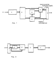
- FIG. 1 shows in a "block diagram" the individual steps of an exemplary embodiment for a coding method according to the invention.
- the (digital) data stream with a high data rate is buffered and "windowed" in an input buffer.
- Level control can also be carried out in this step. This step is essentially the same as for other coding methods.
- N real input values are transformed into the spectral range;
- the discrete Fourier transformation realized with FF transformation
- the cosine transformation or the TDAC transformation (DCT with cancellation of alias components) can be used.
- the coefficients which is also referred to as density storage, can be reduced in the usual way.
- the spectral coefficients are divided into groups of different widths (frequency groups) according to the "sensitivity curve" of the human ear.
- the bandwidth is smaller at low frequencies. This means that fewer frequency bands can be used with the same subjective coding quality than with an even distribution.
- the maximum amplitude is calculated and quantized logarithmically. These values are transmitted to the recipient as additional information.
- the bit allocation takes place.
- the bit allocation is based on the same formula as in the well-known ATC. However, the bit allocation is not carried out individually for each spectral value, but the spectral values of a frequency band are all assigned the same number of bits. The calculation no longer has to be carried out individually for 512 spectral values, for example, but only for 46 frequency groups, for example.
- an adapted minimum number of bits is also allocated to each frequency group, so that it is ensured that the quantization noise is masked (covered) by the useful signal.
- a further reduction in the computing time can be achieved in that "missing" or "leftover" bits are not allocated in an iterative algorithm as in the prior art, but rather, coming from high frequencies, at the next possible position. Although the distribution is not optimal as a result, a subjective deterioration in the coding result cannot be determined and the computing time is considerably reduced.
- the quantization takes place in step 5.
- the inventive formation of the "envelope" enables a considerably simplified quantization by means of a linear quantizer. From the quantized logarithmic maximum amplitude of a frequency band, an upper bound for the spectral values of this frequency band can be determined very easily, for example by accessing the table.
- step 6 a serial bit stream is finally generated in a "multiplexer", which can be transmitted or stored.
- step 6 is demultiplexed, then the bit allocation (5'), the reconstruction of the spectral values as a reverse operation to the quantizer (4 '), the reverse transformation (2') and then the corresponding windowing in an output buffer (1 ').
- the spectral values should be divided into three frequency groups (FG) and 28 bits should be available for coding.
- the DFT is chosen as the transformation.
- the spectral coefficient 8 is deleted.
- the respective log. quantized maximum value of the individual frequency groups is:
- bit allocation takes place. It must be taken into account here that the division into 7 coefficients takes place since the highest frequency is deleted.
- bit numbers have been assigned: thus fewer bits than are available overall (28). This means that 2 bits have to be distributed. For this purpose, high frequencies are used to test in which frequency group this is possible. This is possible for the first time in the 2.FG, so that you finally get:
- the decoding takes place accordingly, so that a detailed description can be omitted here.
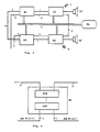
- FIG. 3 shows a multi-signal processor system which is designed for signal processing of audio-stereo signals without restricting the general inventive concept.
- the stereo channels are broken down into a left channel L and a right channel R already after the signal source.
- Each channel has digital signal processing modules M1, M2 or M3 and M4.
- a first communication channel 1 is provided for connecting the signal processing modules M1 ... M4 to the respectively adjacent module or the digital signal source for the respective stereo channel and corresponding subsequent units, such as loudspeakers LS. Since the communication signal 1 is used for signal processing in the manner of "macropipelining", the communication channel 1 is also referred to as a local communication channel.
- a slow communication channel 2 and a fast communication channel 3 are provided, each of which requires a global connection of all modules M1 ... M4.
- FIG. 4 shows an exemplary embodiment for realizing the slow communication channel 2.
- the modules M consist of a digital signal processor DSP and a microcontroller MCU.
- the microcontrollers of the individual modules are connected in series. The connection is established and interrupted again using a special software protocol.
- the slow global communication channel 2 is thus set up in the manner of a normal local network, with the difference that the path is not known to the local system and controls the establishment of the connection from outside no local arbitration takes place.
- slow communication channel 2 is used for system control and parameter adaptation.
- the fast global communication channel 3 provides all the data paths that are still required.
- the fast communication channel is realized by means of a so-called communication controller or communication linker KL and has priority over the slow communication channel 2.
- the individual modules are connected via a microprocessor-like bus.
- the individual modules are largely passive.
- the system is controlled by the higher-level "communication linker" KL.
- the system can therefore be compared to a master-slave system.
- the connection paths are only known to the higher-level controller KL.
- data exchange is requested by the individual sub-modules.
- the higher-level controller then establishes the connection.
- the communication controller essentially functions only as a switching node.
- Local data management is carried out by the sub-modules.
- a "block multiplex transmission is possible", i.e. data traffic is processed on different paths almost simultaneously.
- the data path distribution can be data-dependent, for example, a slight adaptation to the case of a stereo pair or two separate mono channels, a disturbed channel, etc. can take place. Furthermore, the data path distribution can be designed depending on the algorithm. This is the case, for example, if a coding method did not produce an acceptable result in the first run and has to be carried out again with changed parameters.
- system can be used not only for processing digitized audio signals, but also for processing any data signals, such as radar signals, etc.
- the external microcontroller MCU can also be omitted if the digital signal processor DSP used already has a slow communication controller, i.e. the required parts of the MCU are already integrated on the DSP chip.
- the slow communication channels can be connected in series or as a BUS.
- the multi-signal processor system according to the invention can not only be used for real-time implementation of the method described above, but of course also for the implementation of other methods, for example the method known under the name OCF, which is used, for example, in older PCT application DE87 / 00384 is described.
- the best possible output data set is provided which, since the approximation to the optimal final state takes place asymptotically, is the final result that would be obtained if the worst case scenario, i.e. 100% utilization of the digital signal processor DSP, which would allow any computing time, comes very close.
Landscapes
- Engineering & Computer Science (AREA)
- Physics & Mathematics (AREA)
- Acoustics & Sound (AREA)
- Multimedia (AREA)
- Signal Processing (AREA)
- Computational Linguistics (AREA)
- Audiology, Speech & Language Pathology (AREA)
- Human Computer Interaction (AREA)
- Health & Medical Sciences (AREA)
- Spectroscopy & Molecular Physics (AREA)
- Computer Networks & Wireless Communication (AREA)
- General Engineering & Computer Science (AREA)
- Compression, Expansion, Code Conversion, And Decoders (AREA)
- Transmission Systems Not Characterized By The Medium Used For Transmission (AREA)
- Electrophonic Musical Instruments (AREA)
Claims (10)
- Procédé de codage numérique adaptatif par transformées pour la transmission et/ou la mémorisation des signaux acoustiques et en particulier des signaux musicaux,
dans lequel sont transformés' N valeurs explorées dudit signal acoustique dans M coefficients spectraux qui, après un partage dans des groupes de fréquences, sont quantifiés et codés, la valeur quantifiée maximale de chaque groupe de fréquence étant utilisé pour définir la loi approximative du spectre,
caractérisé en ce qu'en codage la même nombre de bits est attribué à toues les valeurs d'un groupe de fréquences, qui dépendent de l'amplitude du coefficient spectral respectif, et
en ce qu'un nombre de bits minimal est attribué à chaque groupe de fréquences de façon que, du point de vue psychoacoustiques, le bruit de quantification soit masqué par le signal utile, en attribuant, si nécessaire, des autres bits in correspondance avec la valeur quantifiée maximale qui est présente dans ce groupe de fréquences. - Procédé selon la revendication 1,
caractérisé en ce que la valeur logarithmique de la valeur maximale de chaque groupe de fréquences subit une quantification linéaire. - Procédé selon la revendication 1 ou 2,
caractérisé en ce que la quantification est réalisée par multiplication et comparaison à une table mémorisée. - Procédé selon une quelconque des revendications 1 à 3,
caractérisé en ce que lesdits N valeurs explorées sont transformées dans M valeurs spectrales moyennent la méthode DFT, DCT ou TDAC. - Système multiproccsseur de signaux, comprenant plusieurs modules de traitement de signaux numériques (M1 ... M4) qui réalisent le procédé son une quelconque des revendications 1 à 4, dans lesquels est exécuté un courant de données, p.e. des audiosignaux numérisés, et comprenant une voie de communication locale (1) qui réalise la communication de données entre des modules voisins (M1 ... M4),
caractérisé en ce qu'au moins une voie de communication globale supplémentaire (2, 3) est prévue par laquelle sont faits l'observation du système, le contrôle du système, l'adaptation de paramètres, et/ou la communication de données globale. - Système multiprocesseur de signaux selon la revendication 5,
caractérisé en ce que deux voies de communication globales (2, 3) sont prévues dont une première voie de communication lente (2) assure le contrôle du système et l'adaptation des paramètres pendant qu'une deuxième voie de communication rapide (3) assure la communication de données. - Système multiprocesseur de signaux selon la revendication 6,
caractérisé en ce qu'un contrôleur de communication (KL) est prévu qui commande la communication de données aléatoire sur ladite voie de communication globale rapide (3). - Système multiprocesseur de signaux selon la revendication 7,
caractérisé en ce que ledit contrôleur de communication (KL) fonctionne en tant que centre de communication. - Système multiprocesseur de signaux selon la revendication 7 ou 8,
caractérisé en ce que ledit contrôleur de communication (KL) commande la distribution de données sur ladite voie de communication globale rapide (3) en fonction de données et/ou d'un algorithme. - Système multiprocesseur de signaux selon la quelconque des revendications 6 à 9,
caractérisé en ce que ladite voie de communication globale rapide (3) est prioritaire vis-a-vis ladite voie de communication globale lente (2).
Priority Applications (1)
| Application Number | Priority Date | Filing Date | Title |
|---|---|---|---|
| AT89901959T ATE90805T1 (de) | 1987-10-06 | 1988-10-06 | Digitales adaptives transformationscodierverfahren. |
Applications Claiming Priority (4)
| Application Number | Priority Date | Filing Date | Title |
|---|---|---|---|
| DE3733772 | 1987-10-06 | ||
| DE3733786 | 1987-10-06 | ||
| DE19873733786 DE3733786A1 (de) | 1987-10-06 | 1987-10-06 | Digitales adaptives transformationscodierverfahren |
| DE19873733772 DE3733772C2 (de) | 1987-10-06 | 1987-10-06 | Multi-Signalprozessorsystem |
Publications (2)
| Publication Number | Publication Date |
|---|---|
| EP0340301A1 EP0340301A1 (fr) | 1989-11-08 |
| EP0340301B1 true EP0340301B1 (fr) | 1993-06-16 |
Family
ID=25860534
Family Applications (1)
| Application Number | Title | Priority Date | Filing Date |
|---|---|---|---|
| EP89901959A Expired - Lifetime EP0340301B1 (fr) | 1987-10-06 | 1988-10-06 | Procede de codage numerique adaptatif par transformees |
Country Status (6)
| Country | Link |
|---|---|
| EP (1) | EP0340301B1 (fr) |
| JP (1) | JP2858122B2 (fr) |
| KR (1) | KR890702178A (fr) |
| AT (1) | ATE90805T1 (fr) |
| DE (1) | DE3881869D1 (fr) |
| WO (1) | WO1989003574A1 (fr) |
Cited By (1)
| Publication number | Priority date | Publication date | Assignee | Title |
|---|---|---|---|---|
| DE102015104775B3 (de) * | 2015-03-27 | 2016-08-04 | Technische Universität Braunschweig | Verfahren zur drahtlosen Datentübertragung sowie Datenübertragungseinrichtung und Computerprogramm |
Families Citing this family (7)
| Publication number | Priority date | Publication date | Assignee | Title |
|---|---|---|---|---|
| US5222189A (en) * | 1989-01-27 | 1993-06-22 | Dolby Laboratories Licensing Corporation | Low time-delay transform coder, decoder, and encoder/decoder for high-quality audio |
| US5752225A (en) * | 1989-01-27 | 1998-05-12 | Dolby Laboratories Licensing Corporation | Method and apparatus for split-band encoding and split-band decoding of audio information using adaptive bit allocation to adjacent subbands |
| WO1991014162A1 (fr) * | 1990-03-13 | 1991-09-19 | Ichikawa, Kozo | Procede et appareil de compression de signaux acoustiques |
| CA2090052C (fr) * | 1992-03-02 | 1998-11-24 | Anibal Joao De Sousa Ferreira | Methode et appareil de codage di signaux audio |
| JP3125543B2 (ja) * | 1993-11-29 | 2001-01-22 | ソニー株式会社 | 信号符号化方法及び装置、信号復号化方法及び装置、並びに記録媒体 |
| US7961507B2 (en) | 2008-03-11 | 2011-06-14 | Micron Technology, Inc. | Non-volatile memory with resistive access component |
| JP6256067B2 (ja) * | 2014-02-06 | 2018-01-10 | 株式会社ソシオネクスト | 半導体装置 |
Family Cites Families (8)
| Publication number | Priority date | Publication date | Assignee | Title |
|---|---|---|---|---|
| SE421151B (sv) * | 1979-01-02 | 1981-11-30 | Ibm Svenska Ab | Kommunikationsstyrenhet i ett databehandlingssystem |
| WO1981001066A1 (fr) * | 1979-10-11 | 1981-04-16 | Nanodata Computer Corp | Systeme de traitement de donnees |
| JPS57167100A (en) * | 1981-04-08 | 1982-10-14 | Nippon Electric Co | Voice coding/decoding system and apparatus provided therefor |
| JPS57204096A (en) * | 1981-06-09 | 1982-12-14 | Nippon Electric Co | Work recognizer |
| US4570220A (en) * | 1983-11-25 | 1986-02-11 | Intel Corporation | High speed parallel bus and data transfer method |
| JPS60200298A (ja) * | 1984-03-24 | 1985-10-09 | 株式会社東芝 | 適応型符号化装置 |
| WO1986003873A1 (fr) * | 1984-12-20 | 1986-07-03 | Gte Laboratories Incorporated | Procede et appareil de codage de la parole |
| DE3629434C2 (de) * | 1986-08-29 | 1994-07-28 | Karlheinz Dipl Ing Brandenburg | Digitales Codierverfahren |
-
1988
- 1988-10-06 AT AT89901959T patent/ATE90805T1/de not_active IP Right Cessation
- 1988-10-06 WO PCT/DE1988/000618 patent/WO1989003574A1/fr not_active Ceased
- 1988-10-06 KR KR1019890701020A patent/KR890702178A/ko not_active Withdrawn
- 1988-10-06 DE DE8989901959T patent/DE3881869D1/de not_active Expired - Lifetime
- 1988-10-06 JP JP63507841A patent/JP2858122B2/ja not_active Expired - Lifetime
- 1988-10-06 EP EP89901959A patent/EP0340301B1/fr not_active Expired - Lifetime
Non-Patent Citations (2)
| Title |
|---|
| ICASSP 82,IEEE International Conference on Acoustics,Speech and Signal Processing, 3-5. May 1987, Paris; volume 3, IEEE, (New York, US) G.J. Bosscha et al.:"DFT-vocoder using harmonic-sieve pitch extraction", pages 1952-1955, paragraph 2.2: "Approximation of the spectral envelope"; paragraph 2.3 "Coding" * |
| ICASSP 86, IEEE-IECEJ-ASJ International Conference of Acoustics, Speech, and Signal Processing, 7-11. April 1986, Tokyo, JP, VOLUME 4, ieee (NEW YORK, US) B. Mazor et al.: "Adaptive subbands excited transform (ASET) coding", pages 3075-3078, see page 3076, left-hand column, lines 5-32 * |
Cited By (1)
| Publication number | Priority date | Publication date | Assignee | Title |
|---|---|---|---|---|
| DE102015104775B3 (de) * | 2015-03-27 | 2016-08-04 | Technische Universität Braunschweig | Verfahren zur drahtlosen Datentübertragung sowie Datenübertragungseinrichtung und Computerprogramm |
Also Published As
| Publication number | Publication date |
|---|---|
| ATE90805T1 (de) | 1993-07-15 |
| DE3881869D1 (de) | 1993-07-22 |
| WO1989003574A1 (fr) | 1989-04-20 |
| JP2858122B2 (ja) | 1999-02-17 |
| JPH02501507A (ja) | 1990-05-24 |
| EP0340301A1 (fr) | 1989-11-08 |
| KR890702178A (ko) | 1989-12-23 |
Similar Documents
| Publication | Publication Date | Title |
|---|---|---|
| DE69116476T2 (de) | Digitaler Signalverschlüssler | |
| DE69219718T2 (de) | Digitales Datenkodierungs-und Dekodierungsgerät mit hoher Wirksamkeit | |
| DE60209888T2 (de) | Kodieren eines audiosignals | |
| DE69319494T2 (de) | Kodierungsvorrichtung für Audiosignalen und Verfahren dazu | |
| DE69401514T2 (de) | Vom rechenaufwand her effiziente adaptive bitzuteilung für kodierverfahren und kodiereinrichtung | |
| DE69333394T2 (de) | Hochwirksames Kodierverfahren und -gerät | |
| DE69225524T2 (de) | Einrichtung zur Orthogonaltransformationskodierung eines digitalen Audiosignals | |
| DE69333786T2 (de) | Verfahren zum Kodieren und Dekodieren von Audiodaten | |
| DE69107841T2 (de) | Transformationskodierer und -dekodierer mit adaptiver blocklänge, adaptiver transformation und adaptivem fenster für hochwertige tonsignale. | |
| DE69525836T2 (de) | Kodierung und dekodierung eines breitbandigen digitalen informationssignals | |
| DE3784120T2 (de) | Tabellengesteuerte dynamische bitverteilung in einem teilband-sprachkodierer mit veraenderlicher datenrate. | |
| DE3878017T2 (de) | System zur teilbandkodierung eines digitalen audiosignals. | |
| DE69232251T2 (de) | Digitaler Kodierer mit dynamischer Quantisierungsbitverteilung | |
| DE69323106T2 (de) | Verfahren und Vorrichtung für perceptuelles Kodieren von Audio-Signalen | |
| DE69924431T2 (de) | Vorrichtung und Verfahren zur dynamischen Bitverteilung für Audiokodierung | |
| EP0290581B1 (fr) | Procede de transmission de signaux audio numerises | |
| DE69326492T2 (de) | Verfahren zur Auswahl des Codier Modus für Stereo Audio-Signale unter Benutzung von Hörbarkeitsmodellen | |
| DE69230308T2 (de) | Transformationsverarbeitungsgerät und -verfahren und Medium zum Speichern komprimierter Digitaldaten | |
| DE2818052C2 (de) | Quantisierung eines Signals mit einem sich über ein gegebenes Frequenzband erstreckendem Spetkrum | |
| DE69023604T2 (de) | Digitalsignalkodiergerät. | |
| EP0277613B1 (fr) | Procédé de transmission de signal audio | |
| DE69428030T2 (de) | Digitales signalkodierungsgerät, dazugehöriges dekodiergerät und aufzeichnungsträger | |
| DE69320872T2 (de) | Kompression und Dehnung von digitalen Signalen | |
| DE19526366A1 (de) | Verfahren zur Redundanzreduktion bei der Codierung von mehrkanaligen Signalen und Vorrichtung zur Dekodierung von redundanzreduzierten, mehrkanaligen Signalen | |
| DE69015105T2 (de) | Kompressionseinrichtung für transformiertes, digitales Audiosignal mit adaptiver Quantisierung auf Grund eines psycho-akustischen Kriteriums. |
Legal Events
| Date | Code | Title | Description |
|---|---|---|---|
| PUAI | Public reference made under article 153(3) epc to a published international application that has entered the european phase |
Free format text: ORIGINAL CODE: 0009012 |
|
| AK | Designated contracting states |
Kind code of ref document: A1 Designated state(s): AT BE CH DE FR GB IT LI LU NL SE |
|
| 17P | Request for examination filed |
Effective date: 19891009 |
|
| 17Q | First examination report despatched |
Effective date: 19910507 |
|
| GRAA | (expected) grant |
Free format text: ORIGINAL CODE: 0009210 |
|
| AK | Designated contracting states |
Kind code of ref document: B1 Designated state(s): AT BE CH DE FR GB IT LI LU NL SE |
|
| REF | Corresponds to: |
Ref document number: 90805 Country of ref document: AT Date of ref document: 19930715 Kind code of ref document: T |
|
| REF | Corresponds to: |
Ref document number: 3881869 Country of ref document: DE Date of ref document: 19930722 |
|
| ITF | It: translation for a ep patent filed | ||
| ET | Fr: translation filed | ||
| GBT | Gb: translation of ep patent filed (gb section 77(6)(a)/1977) |
Effective date: 19931011 |
|
| EPTA | Lu: last paid annual fee | ||
| PLBE | No opposition filed within time limit |
Free format text: ORIGINAL CODE: 0009261 |
|
| STAA | Information on the status of an ep patent application or granted ep patent |
Free format text: STATUS: NO OPPOSITION FILED WITHIN TIME LIMIT |
|
| 26N | No opposition filed | ||
| EAL | Se: european patent in force in sweden |
Ref document number: 89901959.0 |
|
| REG | Reference to a national code |
Ref country code: GB Ref legal event code: IF02 |
|
| REG | Reference to a national code |
Ref country code: CH Ref legal event code: PFA Owner name: FRAUNHOFER-GESELLSCHAFT ZUR FOERDERUNG DER ANGEWA Free format text: FRAUNHOFER-GESELLSCHAFT ZUR FOERDERUNG DER ANGEWANDTEN FORSCHUNG E.V.#LEONRODSTRASSE 54#D-80636 MUENCHEN 19 (DE) -TRANSFER TO- FRAUNHOFER-GESELLSCHAFT ZUR FOERDERUNG DER ANGEWANDTEN FORSCHUNG E.V.#HANSASTRASSE 27 C#80686 MUENCHEN (DE) |
|
| PGFP | Annual fee paid to national office [announced via postgrant information from national office to epo] |
Ref country code: NL Payment date: 20071016 Year of fee payment: 20 Ref country code: LU Payment date: 20071023 Year of fee payment: 20 |
|
| PGFP | Annual fee paid to national office [announced via postgrant information from national office to epo] |
Ref country code: AT Payment date: 20071024 Year of fee payment: 20 Ref country code: IT Payment date: 20071026 Year of fee payment: 20 Ref country code: CH Payment date: 20071023 Year of fee payment: 20 |
|
| PGFP | Annual fee paid to national office [announced via postgrant information from national office to epo] |
Ref country code: BE Payment date: 20071022 Year of fee payment: 20 Ref country code: SE Payment date: 20071023 Year of fee payment: 20 |
|
| PGFP | Annual fee paid to national office [announced via postgrant information from national office to epo] |
Ref country code: GB Payment date: 20071022 Year of fee payment: 20 Ref country code: FR Payment date: 20071019 Year of fee payment: 20 |
|
| PGFP | Annual fee paid to national office [announced via postgrant information from national office to epo] |
Ref country code: DE Payment date: 20071217 Year of fee payment: 20 |
|
| REG | Reference to a national code |
Ref country code: CH Ref legal event code: PCAR Free format text: ALDO ROEMPLER PATENTANWALT;BRENDENWEG 11 POSTFACH 154;9424 RHEINECK (CH) |
|
| REG | Reference to a national code |
Ref country code: CH Ref legal event code: PL |
|
| REG | Reference to a national code |
Ref country code: GB Ref legal event code: PE20 Expiry date: 20081005 |
|
| BE20 | Be: patent expired |
Owner name: *FRAUNHOFER-GESELLSCHAFT ZUR FORDERUNG DER ANGEWAN Effective date: 20081006 |
|
| PG25 | Lapsed in a contracting state [announced via postgrant information from national office to epo] |
Ref country code: NL Free format text: LAPSE BECAUSE OF EXPIRATION OF PROTECTION Effective date: 20081006 |
|
| NLV7 | Nl: ceased due to reaching the maximum lifetime of a patent |
Effective date: 20081006 |
|
| EUG | Se: european patent has lapsed | ||
| PG25 | Lapsed in a contracting state [announced via postgrant information from national office to epo] |
Ref country code: GB Free format text: LAPSE BECAUSE OF EXPIRATION OF PROTECTION Effective date: 20081005 |