EP0340312A1 - Drahtverbindungsfertigstellungsdetektor - Google Patents
Drahtverbindungsfertigstellungsdetektor Download PDFInfo
- Publication number
- EP0340312A1 EP0340312A1 EP88909364A EP88909364A EP0340312A1 EP 0340312 A1 EP0340312 A1 EP 0340312A1 EP 88909364 A EP88909364 A EP 88909364A EP 88909364 A EP88909364 A EP 88909364A EP 0340312 A1 EP0340312 A1 EP 0340312A1
- Authority
- EP
- European Patent Office
- Prior art keywords
- wire
- extension
- roller
- rotary member
- disc
- Prior art date
- Legal status (The legal status is an assumption and is not a legal conclusion. Google has not performed a legal analysis and makes no representation as to the accuracy of the status listed.)
- Granted
Links
- 238000001514 detection method Methods 0.000 claims description 9
- 238000011144 upstream manufacturing Methods 0.000 claims 1
- 238000003754 machining Methods 0.000 description 9
- 239000007788 liquid Substances 0.000 description 4
- 230000002093 peripheral effect Effects 0.000 description 3
- 238000010586 diagram Methods 0.000 description 2
- 238000011084 recovery Methods 0.000 description 2
- 239000003990 capacitor Substances 0.000 description 1
- 238000003780 insertion Methods 0.000 description 1
- 230000037431 insertion Effects 0.000 description 1
- 238000000034 method Methods 0.000 description 1
- 230000001960 triggered effect Effects 0.000 description 1
Images
Classifications
-
- B—PERFORMING OPERATIONS; TRANSPORTING
- B23—MACHINE TOOLS; METAL-WORKING NOT OTHERWISE PROVIDED FOR
- B23H—WORKING OF METAL BY THE ACTION OF A HIGH CONCENTRATION OF ELECTRIC CURRENT ON A WORKPIECE USING AN ELECTRODE WHICH TAKES THE PLACE OF A TOOL; SUCH WORKING COMBINED WITH OTHER FORMS OF WORKING OF METAL
- B23H7/00—Processes or apparatus applicable to both electrical discharge machining and electrochemical machining
- B23H7/02—Wire-cutting
- B23H7/08—Wire electrodes
- B23H7/10—Supporting, winding or electrical connection of wire-electrode
Definitions
- the present invention relates to a wire-extension end detector for a wire-cut electric discharge machine, which is highly reliable in detecting action.
- An apparatus provided in a wire-cut electric discharge machine for carrying out an automatic extension of a wire, disconnected intentionally to allow a workpiece to be shifted to change a discharge machining portion thereof or disconnected accidentally during the discharge machining is disclosed in Japanese Patent Disclosure No. 62-44319, for example.
- a wire supplied through a wire passage of an upper wire guide arranged above a workpiece, is fed into a groove or hole of the workpiece while being restricted by a machining liquid jetted from a nozzle formed in the upper wire guide, and is then passed through a wire passage of a lower wire guide.
- the wire is fed to a conveyor device arranged under the lower wire guide and including a pair of belts pressed against each other, so that the wire is conveyed, while held between the belts, in between a wire drive roller and a pinch roller arranged downstream of the conveyor device.
- the wire extension is completed when the wire is held between the wire drive roller and the pinch roller.
- an electric power supplying section which is electrically connected to the wire becomes connected, through the wire, the electrically conductive outer peripheral wall of the wire drive roller, and an electrically conductive brush pressed against the outer wall of the wire drive roller, to an electric power supplied section which is connected to the brush.
- the resulting supply of electric power from the power supplying section to the power supplied section is detected by a suitable means as an end of wire extension.
- the prior art wire-extension end detector uses the brush pressed against the wire drive roller, and therefore is liable to suffer disconnection between the brush and the roller as the brush is worn away with long use, thus failing to detect the end of a wire extension.
- An object of the present invention is to provide an automatic wire-extension end detector for a wire-cut electric discharge machine, which does not use electrical components that mechanically contact one another, and thus is capable of highly reliable detection of the end of a wire extension.
- a wire-extension end detector of the present invention is provided in a wire-cut electric discharge machine which has a wire conveyor device including wire drive means for running a wire delivered by automatic wire extension means.
- the wire-extension end detector comprises: a rotary member arranged to face a wire travel path and rotatively driven by the wire which is driven to travel by the wire drive means; detection means arranged in a non-contact relation to the rotary member, for generating an output indicating that the rotary member is rotating, when the rotary member is rotated; and discrimination means responsive to an operation of the wire drive means, an operation of the automatic wire extension means, and to the output of the detection means.
- the discrimination means is operable to detect the end of a wire extension when an output of the detection means is generated before a predetermined time passes after the start of operation of the automatic wire extension means, during the operation of the wire drive means.
- the wire-extension end detector of the present invention is so arranged as to detect the end of a wire extension in a non-contact fashion at which the wire is brought to be driven to travel by the wire drive means, without using any electrical components that mechanically contact one another, and accordingly can reliably detect the end of the wire extension.
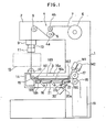
- a wire-cut electric discharge machine comprises a column 1 having a wire feed bobbin 6 arranged at an upper portion thereof.
- An upper arm 2 extending substantially horizontally from one end face of the column is provided with a braking device 4, which is composed of a pinch roller 4b and a tension brake roller 4a cooperating with the roller 4b to apply a tension force on a wire 7.
- the upper arm 2 is also provided with a guide roller 8 for guiding the wire 7, a U-V axis unit 9, and an upper wire guide 10 driven by the unit 9 to be movable within a horizontal plane.
- To the upper wire guide 10 is mounted an automatic wire extension means 11 of a conventionally known type.
- a workpiece 12 located between the opposed wire guides is placed on a work table (not shown) which is movable within a horizontal plane.
- the lower arm 3 is provided further with a guide block 14 and a guide roller 15 opposed to each other for cooperatively guiding the wire 7, and a conveyor means 16 arranged downstream of the roller 15.
- the conveyor means 16 comprises an upper conveyor 16a and a lower conveyor 16b movable toward and away from the upper conveyor 16a.
- the upper conveyor 16a includes a plurality of rollers (only two of them are illustrated with numerals 161 and 162) rotatably supported by the lower arm 3, and a belt 163 wound around these rollers.
- the roller 162 at the downstream end is coupled to a motor Ml.
- the lower conveyor 16b includes a plurality of rollers (only two of them are illustrated with numerals 165 and 166) around which a belt 164 is wound, and a pair of side plates (only one of them is illustrated with numeral 21) rotatably supporting the rollers.
- the lower conveyor is swingably supported by the lower arm 3 through a plurality of links 22 coupled at respective one end to the side plates and coupled at another end or an intermediate portion thereof to the lower arm 3.
- the link 22 at the downstream end is urged by a spring 23 in a direction along which the lower conveyor 16b is moved away from the upper conveyor 16a, and has an end coupled to the distal end of a piston rod 20a of an air cylinder 20.
- a wire drive roller 17 coupled to a motor M2, a pinch roller 18 pressed against the roller 17, and a wire recovery box 19.
- a wire-extension end detector is used with the automatic wire extension and conveyance apparatus composed of the aforementioned elements 4, 8-11, 13-18, 20-22, M1 and M2.
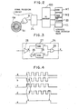
- the wire-extension end detector comprises, as shown in Fig. 2, a disc 4c secured to the tension brake roller 4a and having a black-and-while code pattern thereon, a photoelectric switch 5 opposed to the disc 4c and having a light projecting portion and a light receiving portion, a signal processing circuit 24 connected to the switch 5, and a numerical control apparatus 100 connected to the elements 11, 20, 24, M1 and M2.
- the signal processing circuit 24 comprises, as shown in Fig.
- an amplifier 25 having an input terminal connected to the output terminal of the photoelectric switch 5
- timers 27 and 28 having individual input terminals connected to the output terminal of the amplifier 25 directly and indirectly through an inverter 26, respectively
- an OR circuit 29 having input terminals connected to the respective output terminals of the timers.
- the timers each comprise a retriggerable one-shot multivibrator whose pulse width is variably adjustable in accordance with the speed of travel of the wire, for example.
- the air cylinder 20 and the motors M1 and M2 are actuated to move the lower conveyor 16b toward the upper conveyor 16a until the belts of these conveyors are in urging contact with each other, whereby the belts run, at the side of their opposed surfaces, from left to right in Fig. 1 with counterclockwise rotation of the roller 162.
- the wire 7 inserted into the wire passage of the lower wire guide 13 is guided between the belts by the guide block 14 and the guide roller 15.
- the wire 7 is conveyed while being held between the belts and finally has the leading end thereof held between the wire drive roller 17 and the pinch roller 18. Thereafter, with rotation of the roller 17, the wire 7 is conveyed while being held between the rollers 17 and 18.
- the tension brake roller 4a cooperating with the pinch roller 4b to hold the wire 7 in between, and thus the disc 4c secured to the roller 4a are rotated.
- the photoelectric switch 5 which projects light from its light projecting portion toward the disc 4c for reflection, receives light whose amount varies in accordance with the black-and-white pattern of the disc 4c, at its light receiving portion, and delivers a corresponding pulse train which is amplified by the amplifier 25 to obtain a pulse train a.
- the pulse train a is applied to the timer 27 and the inverter 26.
- the timers 27 and 28 are triggered, respectively, by the rise of each pulse of the pulse train a and the rise of each pulse of a pulse train b delivered from the inverter 26, and provide pulse trains c and having respective predetermined pulse widths, respectively.
- the pulse widths of the pulse trains c and d are set to values in accordance with the travel speed of the wire, more particularly, to values slightly larger than the half of the pulse width of the pulse train supplied from the photoelectric switch 5.
- the wire 7 is conveyed at a predetermined speed by the wire drive roller 17, at least one of the pulse trains c and d is H-level, and accordingly an output e of the OR circuit 29 to which both the pulse trains are applied maintains H-level indicative of a wire extended state.
- the numerical control apparatus 10 When the H-level output is received from the OR circuit 29 during a predetermined time after the start of the wire extension, the numerical control apparatus 10 renders the air cylinder 20 and the motor M1 inoperative. As a result, the lower conveyor 16b is moved away from the upper conveyor 16a by the force of the spring 23, and thus the belt 164 of the lower conveyor 3 is set apart from the wire 7.
- the belt 163 of the upper conveyor 16a is positioned such that its surface facing the wire 7 is spaced therefrom when the wire is tensed between the rollers 15 and 18, and therefore is also brought to a non-contact state with the wire 7. Thus, the belts 163 and 164 stop running. Thereafter, the wire 7 is conveyed by the wire drive roller 17 and the pinch roller 18 which are driven by the motor M2 continuously after the wire extension, and the wire 7 used for the discharge machining is deposited in the wire recovery box 19.
- the tension brake roller 4a and the disc 4c integral therewith are not rotated. Therefore, no pulse train is sent from the photoelectric switch 5, thus maintaining the output of the signal processing circuit 24 at L-level indicative of incompleteness of wire extension. If the output of the circuit 24 is still L-level when the predetermined time, which is set to a value longer than a normally required wire extension time, passes after the start of the wire extension, the numerical control apparatus 100 judges that the wire extension failed, and retries a wire extension in accordance with the aforementioned procedure.
- the embodiment described above uses the signal processing circuit 24 including two timers 27 and 28, but a circuit including one timer may alternatively be used.
- the width of the output pulse from the timer is set to a value larger than the output pulse width of the photoelectric switch 5.
- an R-C circuit may alternatively be used such that a capacitor, charged above a predetermined level by the H-level output of the amplifier 25, is discharged below the predetermined level through a resistor before a time slightly longer than the L-level time of the amplifier 25 passes after the inversion of the output level.
- completion of a wire extension is detected optically using the disc 4c rotatable with the tension brake roller 4a and having a black-and-white pattern thereon, and the photoelectric switch 5.
- Such detection may alternatively be effected magnetically or electrically.
Landscapes
- Chemical & Material Sciences (AREA)
- Chemical Kinetics & Catalysis (AREA)
- Electrochemistry (AREA)
- Engineering & Computer Science (AREA)
- Mechanical Engineering (AREA)
- Electrical Discharge Machining, Electrochemical Machining, And Combined Machining (AREA)
Applications Claiming Priority (2)
| Application Number | Priority Date | Filing Date | Title |
|---|---|---|---|
| JP269344/87 | 1987-10-27 | ||
| JP62269344A JPH01115520A (ja) | 1987-10-27 | 1987-10-27 | ワイヤ自動結線終了検出方式 |
Publications (3)
| Publication Number | Publication Date |
|---|---|
| EP0340312A1 true EP0340312A1 (de) | 1989-11-08 |
| EP0340312A4 EP0340312A4 (de) | 1989-12-18 |
| EP0340312B1 EP0340312B1 (de) | 1992-08-19 |
Family
ID=17471071
Family Applications (1)
| Application Number | Title | Priority Date | Filing Date |
|---|---|---|---|
| EP88909364A Expired - Lifetime EP0340312B1 (de) | 1987-10-27 | 1988-10-27 | Drahtverbindungsfertigstellungsdetektor |
Country Status (6)
| Country | Link |
|---|---|
| US (1) | US5013881A (de) |
| EP (1) | EP0340312B1 (de) |
| JP (1) | JPH01115520A (de) |
| KR (1) | KR890701269A (de) |
| DE (1) | DE3873909T2 (de) |
| WO (1) | WO1989003743A1 (de) |
Cited By (2)
| Publication number | Priority date | Publication date | Assignee | Title |
|---|---|---|---|---|
| DE4013432A1 (de) * | 1989-04-28 | 1990-10-31 | Mitsubishi Electric Corp | Vorrichtung zur zufuhr einer drahtelektrode bei einer elektroerosiv-bearbeitungseinheit |
| CN109514210A (zh) * | 2019-01-10 | 2019-03-26 | 江阴普洋法兰有限公司 | 一种大型双头连轴法兰的毛坯制作工艺及工装 |
Families Citing this family (6)
| Publication number | Priority date | Publication date | Assignee | Title |
|---|---|---|---|---|
| US5051410A (en) * | 1988-09-01 | 1991-09-24 | Massachusetts Institute Of Technology | Method and composition for enhancing the release of neurotransmitters |
| JP2616110B2 (ja) * | 1990-03-13 | 1997-06-04 | 三菱電機株式会社 | ワイヤ放電加工装置 |
| JP2006136986A (ja) * | 2004-11-12 | 2006-06-01 | Makino Milling Mach Co Ltd | ワイヤ放電加工機及びその自動結線方法 |
| JP4849810B2 (ja) * | 2005-03-08 | 2012-01-11 | 株式会社牧野フライス製作所 | ワイヤ放電加工機及びその自動結線方法 |
| JP5199447B1 (ja) * | 2011-12-09 | 2013-05-15 | ファナック株式会社 | 回転軸を備えたワイヤ放電加工機 |
| CN104790149B (zh) * | 2014-01-16 | 2018-03-20 | 福懋兴业股份有限公司 | 连续性纤维丝束的处理设备及方法 |
Family Cites Families (10)
| Publication number | Priority date | Publication date | Assignee | Title |
|---|---|---|---|---|
| US4513191A (en) * | 1980-05-13 | 1985-04-23 | Inoue-Japax Research Incorporated | Method of and apparatus for resetting a wire electrode in an operating setup on an electroerosion machine |
| JPS5783364A (en) * | 1980-11-10 | 1982-05-25 | Inoue Japax Res Inc | Wires setting device for wire type discharge processing machine |
| JPS57149126A (en) * | 1981-03-11 | 1982-09-14 | Mitsubishi Electric Corp | Wire electrode feeder of wire cut electric discharge machining device |
| JPS58177234A (ja) * | 1982-04-07 | 1983-10-17 | Mitsubishi Electric Corp | ワイヤカツト放電加工装置におけるワイヤ自動供給方法 |
| JPS58202724A (ja) * | 1982-05-06 | 1983-11-26 | Mitsubishi Electric Corp | ワイヤカツト放電加工装置におけるワイヤ自動供給装置 |
| JPS58188126U (ja) * | 1982-06-08 | 1983-12-14 | 株式会社井上ジャパックス研究所 | ワイヤカツト放電加工装置 |
| JPS6013286A (ja) * | 1983-07-04 | 1985-01-23 | 株式会社東芝 | 原子炉格納容器の支持装置 |
| JPS629827A (ja) * | 1985-07-04 | 1987-01-17 | Fanuc Ltd | ワイヤカツト放電加工方法と装置 |
| FR2588137B1 (fr) * | 1985-10-01 | 1988-01-08 | Jice Automat Soc | Dispositif de codage et de lecture pour des organes porteurs de pieces a diriger vers des postes de travail determines. |
| JPH0669651B2 (ja) * | 1985-11-20 | 1994-09-07 | 三菱電機株式会社 | ワイヤ自動供給装置 |
-
1987
- 1987-10-27 JP JP62269344A patent/JPH01115520A/ja active Pending
-
1988
- 1988-10-27 US US07/378,195 patent/US5013881A/en not_active Expired - Fee Related
- 1988-10-27 EP EP88909364A patent/EP0340312B1/de not_active Expired - Lifetime
- 1988-10-27 WO PCT/JP1988/001089 patent/WO1989003743A1/ja not_active Ceased
- 1988-10-27 DE DE8888909364T patent/DE3873909T2/de not_active Expired - Fee Related
-
1989
- 1989-04-24 KR KR1019890700714A patent/KR890701269A/ko not_active Ceased
Non-Patent Citations (1)
| Title |
|---|
| See references of WO8903743A1 * |
Cited By (2)
| Publication number | Priority date | Publication date | Assignee | Title |
|---|---|---|---|---|
| DE4013432A1 (de) * | 1989-04-28 | 1990-10-31 | Mitsubishi Electric Corp | Vorrichtung zur zufuhr einer drahtelektrode bei einer elektroerosiv-bearbeitungseinheit |
| CN109514210A (zh) * | 2019-01-10 | 2019-03-26 | 江阴普洋法兰有限公司 | 一种大型双头连轴法兰的毛坯制作工艺及工装 |
Also Published As
| Publication number | Publication date |
|---|---|
| WO1989003743A1 (fr) | 1989-05-05 |
| KR890701269A (ko) | 1989-12-19 |
| DE3873909T2 (de) | 1993-01-14 |
| EP0340312B1 (de) | 1992-08-19 |
| DE3873909D1 (de) | 1992-09-24 |
| JPH01115520A (ja) | 1989-05-08 |
| EP0340312A4 (de) | 1989-12-18 |
| US5013881A (en) | 1991-05-07 |
Similar Documents
| Publication | Publication Date | Title |
|---|---|---|
| EP0472412B1 (de) | Verfahren zur Zustandserfassung beim Schneiden einer Gummibahn mit eingebetteten parallelen Fäden | |
| EP0340312B1 (de) | Drahtverbindungsfertigstellungsdetektor | |
| US4620466A (en) | Cutting machine | |
| JPH02224926A (ja) | ワイヤ放電加工装置のワイヤ自動供給装置 | |
| US4814572A (en) | Apparatus for detecting completion of automatic wire setting | |
| JPS60162544A (ja) | ねじ転造機におけるねじのスベリ不良検出装置 | |
| EP0366812A1 (de) | Detektor für drahtbrüche | |
| ES455042A1 (es) | Procedimiento y dispositivo para conocer el trabajo defec- tuoso de aparatos de hilar en maquinas hiladoras con extremoabierto. | |
| JPS5833056B2 (ja) | 電気スパ−ク浸食切断装置の電極ワイヤ−位置ぎめ装置 | |
| EP0328682A1 (de) | Drahtzufuhr | |
| JP2812492B2 (ja) | ワイヤカット放電加工機においてワイヤ電極がワイヤ搬出側のワイヤガイド部を挿通したことを確認する方法および装置 | |
| KR100406146B1 (ko) | 와이어 톱의 와이어 탈선 검출장치 | |
| IT9020731A1 (it) | Macchina da taglio ad elettrodo a filo a scarica elettrica | |
| JPS63312025A (ja) | ワイヤ放電加工装置のワイヤ電極回収機構 | |
| KR920006507B1 (ko) | 와이어 방전 가공장치 | |
| JP2577579B2 (ja) | ワイヤ断線検出装置 | |
| JPS6342982Y2 (de) | ||
| JPH0471647B2 (de) | ||
| JP3744968B2 (ja) | ワイヤ放電加工機の自動ワイヤ供給装置 | |
| JPS5828427A (ja) | 放電切断機のワイヤに負荷をかける装置 | |
| JPS6263018A (ja) | ワイヤカツト放電加工機におけるワイヤ電極断線位置検出方法 | |
| JP3013904B2 (ja) | ワイヤ自動結線装置 | |
| JPH05305523A (ja) | ワイヤ放電加工機におけるワイヤ電極の自動結線装置 | |
| JPH02106226A (ja) | ワイヤ電極供給確認方法 | |
| JPH0632501A (ja) | 織布巻取り初期における布端巻付け不良検出装置 |
Legal Events
| Date | Code | Title | Description |
|---|---|---|---|
| PUAI | Public reference made under article 153(3) epc to a published international application that has entered the european phase |
Free format text: ORIGINAL CODE: 0009012 |
|
| 17P | Request for examination filed |
Effective date: 19890711 |
|
| AK | Designated contracting states |
Kind code of ref document: A1 Designated state(s): CH DE FR GB IT LI |
|
| A4 | Supplementary search report drawn up and despatched |
Effective date: 19891218 |
|
| 17Q | First examination report despatched |
Effective date: 19910506 |
|
| GRAA | (expected) grant |
Free format text: ORIGINAL CODE: 0009210 |
|
| AK | Designated contracting states |
Kind code of ref document: B1 Designated state(s): CH DE FR GB IT LI |
|
| PG25 | Lapsed in a contracting state [announced via postgrant information from national office to epo] |
Ref country code: FR Effective date: 19920819 Ref country code: IT Free format text: LAPSE BECAUSE OF FAILURE TO SUBMIT A TRANSLATION OF THE DESCRIPTION OR TO PAY THE FEE WITHIN THE PRE;WARNING: LAPSES OF ITALIAN PATENTS WITH EFFECTIVE DATE BEFORE 2007 MAY HAVE OCCURRED AT ANY TIME BEFORE 2007. THE CORRECT EFFECTIVE DATE MAY BE DIFFERENT FROM THE ONE RECORDED.SCRIBED TIME-LIMIT Effective date: 19920819 |
|
| REF | Corresponds to: |
Ref document number: 3873909 Country of ref document: DE Date of ref document: 19920924 |
|
| PG25 | Lapsed in a contracting state [announced via postgrant information from national office to epo] |
Ref country code: GB Effective date: 19921119 |
|
| EN | Fr: translation not filed | ||
| PLBE | No opposition filed within time limit |
Free format text: ORIGINAL CODE: 0009261 |
|
| STAA | Information on the status of an ep patent application or granted ep patent |
Free format text: STATUS: NO OPPOSITION FILED WITHIN TIME LIMIT |
|
| GBPC | Gb: european patent ceased through non-payment of renewal fee |
Effective date: 19921119 |
|
| 26N | No opposition filed | ||
| PGFP | Annual fee paid to national office [announced via postgrant information from national office to epo] |
Ref country code: DE Payment date: 19951026 Year of fee payment: 8 |
|
| PGFP | Annual fee paid to national office [announced via postgrant information from national office to epo] |
Ref country code: CH Payment date: 19951113 Year of fee payment: 8 |
|
| PG25 | Lapsed in a contracting state [announced via postgrant information from national office to epo] |
Ref country code: LI Effective date: 19961031 Ref country code: CH Effective date: 19961031 |
|
| REG | Reference to a national code |
Ref country code: CH Ref legal event code: PL |
|
| PG25 | Lapsed in a contracting state [announced via postgrant information from national office to epo] |
Ref country code: DE Effective date: 19970701 |