EP0340317A1 - Induktiver Wegaufnehmer - Google Patents
Induktiver Wegaufnehmer Download PDFInfo
- Publication number
- EP0340317A1 EP0340317A1 EP88106985A EP88106985A EP0340317A1 EP 0340317 A1 EP0340317 A1 EP 0340317A1 EP 88106985 A EP88106985 A EP 88106985A EP 88106985 A EP88106985 A EP 88106985A EP 0340317 A1 EP0340317 A1 EP 0340317A1
- Authority
- EP
- European Patent Office
- Prior art keywords
- coil
- induction
- coils
- core
- sensor according
- Prior art date
- Legal status (The legal status is an assumption and is not a legal conclusion. Google has not performed a legal analysis and makes no representation as to the accuracy of the status listed.)
- Granted
Links
- 230000001939 inductive effect Effects 0.000 title claims abstract description 7
- 230000006698 induction Effects 0.000 claims abstract description 73
- 239000000463 material Substances 0.000 claims abstract description 9
- 238000006073 displacement reaction Methods 0.000 claims description 25
- 238000007654 immersion Methods 0.000 claims description 4
- 238000004804 winding Methods 0.000 claims description 3
- 238000005259 measurement Methods 0.000 abstract description 4
- 238000010276 construction Methods 0.000 abstract 1
- 230000004907 flux Effects 0.000 description 10
- 210000003298 dental enamel Anatomy 0.000 description 2
- 238000004519 manufacturing process Methods 0.000 description 2
- 229910000831 Steel Inorganic materials 0.000 description 1
- 230000004323 axial length Effects 0.000 description 1
- 230000015572 biosynthetic process Effects 0.000 description 1
- 238000010586 diagram Methods 0.000 description 1
- 230000000694 effects Effects 0.000 description 1
- 238000009413 insulation Methods 0.000 description 1
- 230000000717 retained effect Effects 0.000 description 1
- 239000010959 steel Substances 0.000 description 1
- 238000007669 thermal treatment Methods 0.000 description 1
- 239000002699 waste material Substances 0.000 description 1
Images
Classifications
-
- G—PHYSICS
- G01—MEASURING; TESTING
- G01D—MEASURING NOT SPECIALLY ADAPTED FOR A SPECIFIC VARIABLE; ARRANGEMENTS FOR MEASURING TWO OR MORE VARIABLES NOT COVERED IN A SINGLE OTHER SUBCLASS; TARIFF METERING APPARATUS; MEASURING OR TESTING NOT OTHERWISE PROVIDED FOR
- G01D5/00—Mechanical means for transferring the output of a sensing member; Means for converting the output of a sensing member to another variable where the form or nature of the sensing member does not constrain the means for converting; Transducers not specially adapted for a specific variable
- G01D5/12—Mechanical means for transferring the output of a sensing member; Means for converting the output of a sensing member to another variable where the form or nature of the sensing member does not constrain the means for converting; Transducers not specially adapted for a specific variable using electric or magnetic means
- G01D5/14—Mechanical means for transferring the output of a sensing member; Means for converting the output of a sensing member to another variable where the form or nature of the sensing member does not constrain the means for converting; Transducers not specially adapted for a specific variable using electric or magnetic means influencing the magnitude of a current or voltage
- G01D5/20—Mechanical means for transferring the output of a sensing member; Means for converting the output of a sensing member to another variable where the form or nature of the sensing member does not constrain the means for converting; Transducers not specially adapted for a specific variable using electric or magnetic means influencing the magnitude of a current or voltage by varying inductance, e.g. by a movable armature
- G01D5/2006—Mechanical means for transferring the output of a sensing member; Means for converting the output of a sensing member to another variable where the form or nature of the sensing member does not constrain the means for converting; Transducers not specially adapted for a specific variable using electric or magnetic means influencing the magnitude of a current or voltage by varying inductance, e.g. by a movable armature by influencing the self-induction of one or more coils
- G01D5/2013—Mechanical means for transferring the output of a sensing member; Means for converting the output of a sensing member to another variable where the form or nature of the sensing member does not constrain the means for converting; Transducers not specially adapted for a specific variable using electric or magnetic means influencing the magnitude of a current or voltage by varying inductance, e.g. by a movable armature by influencing the self-induction of one or more coils by a movable ferromagnetic element, e.g. a core
-
- G—PHYSICS
- G01—MEASURING; TESTING
- G01D—MEASURING NOT SPECIALLY ADAPTED FOR A SPECIFIC VARIABLE; ARRANGEMENTS FOR MEASURING TWO OR MORE VARIABLES NOT COVERED IN A SINGLE OTHER SUBCLASS; TARIFF METERING APPARATUS; MEASURING OR TESTING NOT OTHERWISE PROVIDED FOR
- G01D5/00—Mechanical means for transferring the output of a sensing member; Means for converting the output of a sensing member to another variable where the form or nature of the sensing member does not constrain the means for converting; Transducers not specially adapted for a specific variable
- G01D5/12—Mechanical means for transferring the output of a sensing member; Means for converting the output of a sensing member to another variable where the form or nature of the sensing member does not constrain the means for converting; Transducers not specially adapted for a specific variable using electric or magnetic means
- G01D5/14—Mechanical means for transferring the output of a sensing member; Means for converting the output of a sensing member to another variable where the form or nature of the sensing member does not constrain the means for converting; Transducers not specially adapted for a specific variable using electric or magnetic means influencing the magnitude of a current or voltage
- G01D5/20—Mechanical means for transferring the output of a sensing member; Means for converting the output of a sensing member to another variable where the form or nature of the sensing member does not constrain the means for converting; Transducers not specially adapted for a specific variable using electric or magnetic means influencing the magnitude of a current or voltage by varying inductance, e.g. by a movable armature
- G01D5/22—Mechanical means for transferring the output of a sensing member; Means for converting the output of a sensing member to another variable where the form or nature of the sensing member does not constrain the means for converting; Transducers not specially adapted for a specific variable using electric or magnetic means influencing the magnitude of a current or voltage by varying inductance, e.g. by a movable armature differentially influencing two coils
Definitions
- the invention relates to an inductive displacement transducer with two coaxially arranged in a measuring bridge induction coils of the same induction direction, with axially movably mounted coil core made of magnetizable material depending on the path to be measured and with a third coil which is arranged and dimensioned so that you Magnetic field in an area of the transducer such a superposition of the magnetic field of an adjacent induction coil has the effect that the drop in induction at one end of the induction coil is canceled, the length of the coil core and its range of motion being dimensioned such that the coil core passes through in each of its positions the third coil projects through and the third coil is inserted into at least one of the two branches of the measuring bridge.
- Such a displacement sensor is known from DE-PS 35 28 811.
- the coil core projects into the interior of induction coils to different degrees in accordance with the path to be measured and consequently shifts the potential in the induction coils.
- a differential voltage which serves as a measure of the path to be measured, can be measured in the diagonal of an electrical measuring bridge. Since with induction coils the induction does not run linearly over the entire length of the coil, a compensation coil is provided in the known displacement sensor between two induction coils; in each of its positions, the coil core projects through the compensation coil into a part of each of the induction coils. With this configuration, a linearization of the measurement signal of the displacement transducer is achieved enough. Although the space requirement for the compensation coil between the two induction coils is negligible, the overall length, which is essentially determined by the arrangement of the two induction coils, is relatively large.
- the invention has for its object to provide an inductive displacement transducer, in which a linearization of the measurement signal is achieved with a compact design with simple and effective means.
- this object is achieved in a displacement transducer according to the preamble of claim 1 by the features specified in the characterizing part of the claim.
- the magnetic flux and the flux density values change in the third coil, as a result of which the linearity of the output signal is influenced. If the coil core is only slightly pushed into the first induction coil near its one end position, there is a greater magnetic flux or a greater flux density through the third coil and these adjacent components than in the case in which the coil core is almost close to the other end position fully inserted in the first induction coil; in the latter case there is a smaller flux or a smaller flux density in the third coil and adjacent components, since the second coil is now also effectively coupled into the magnetic circuit and has a considerable influence on the magnetic circuit.
- the change in the flow and thus the change in the magnetic resistance influences the linearization of the output signal of the displacement sensor.
- bundle the magnet field of the third coil and that of the second coil, the magnetic field of the first coil, as a result of which negligible leakage flux occurs at the end regions of the first coil and the inductive properties of the entire arrangement are linearized.
- the ratio of overall length to measuring path is thus improved to values close to 1. There is no additional space requirement in the radial direction.
- a displacement transducer which is designed to be economical to manufacture is obtained in one embodiment of the invention in which one of the coils adjacent to the first induction coil, in particular the third coil acting as a compensation coil, is designed as a double coil.
- the two sub-coils of the third coil are each connected in series with one of the further induction coils in one branch of an electrical AC half-bridge. It is advantageous here that the bridge equilibrium is ensured by inserting a partial coil into the respective measuring bridge branch without an additional compensation resistor being required.
- a parallel wire winding is expedient for this coil.
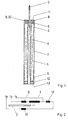
- the inductive displacement sensor has an induction coil 1, in the interior of which a coil core 2 made of magnetizable material is slidably mounted along the coil axis.
- the coil core 2 is connected via a connecting linkage 3 to a component whose displacement path is to be measured.
- the induction coil 1 is wound on a coil carrier tube 4 made of non-magnetizable material. At the axial ends of the induction coil 1, a ring element 5 or 6 made of plastic is arranged. The induction coil 1 is accommodated in a jacket tube 7 made of magnetizable material, in the exemplary embodiment a steel tube.
- a compensation coil 8 composed of two partial coils 9 and 10 is arranged inside the jacket tube 7 on the immersion side of the coil core 2 adjacent to the ring element 5 and coaxially with the induction coil 1.
- the coil 8 is designed as a double coil with a parallel wire winding and is penetrated by an extension of the coil carrier tube 4.
- the insulations of the parallel wires are connected to one another, for example, by thermal treatment, so that the two parallel wires form a unitary structure (baked enamel double coil).
- an annular disk 11 made of magnetizable material is arranged, which delimits the cavity between the coil carrier tube 4 and the jacket tube 7 on this end face.
- the induction coil 12 is designed as a baked enamel coil and is penetrated by an extension of the coil carrier tube 4.
- annular disc 13 made of magnetizable material is arranged, which closes the cavity between the coil carrier tube 4 and jacket tube 7 on the second end face.
- the axial extent of the induction coil 1 is many times greater than that of the coil 8 or the partial coils 9 and 10 and the coil 12, which have approximately the same axial extent.
- the coil core 2 projects through the third coil 8 into the first coil 1 in each of its positions.
- the displacement path of the end of the coil core 2 lies completely within the induction coil 1.
- All coils 1, 9, 10 and 12 have the same induction directions in the illustrated embodiment. However, it can also be provided that the direction of induction of the third coil 8 is selected opposite to the direction of induction of the first and second induction coils 1 and 12, respectively.
- the compensation coil 8 is arranged with each of its partial coils 9 and 10 in one branch of a half bridge. Accordingly, the induction coils 1 and 9 are in one branch of a half-bridge and in the other
- Branch of the half-bridge arranged the induction coils 10 and 12.
- the supplementary half bridge is located in the measuring amplifier used for the measurement.
- the half-bridge is supplied with a carrier frequency voltage U B , the output voltage U A is tapped.
- the formation of the compensation coil 8 as a double coil, each consisting of partial coils arranged in a bridge branch, has the advantage that the bridge balance is retained without compensation resistors or only minimal compensation resistors being required.
- the coils according to the invention Due to the arrangements, configurations and mutual coordination of the coils according to the invention, namely in particular a very long induction coil 1 in comparison to the induction coils 8 and 12 for measuring the distance by displacement of the coil core 2 within this induction coil 1, the coil 8 acting as a compensation coil on the immersion side of the coil core 2 and the induction coil 12 acting as a compensation coil at the other end of the induction coil 1, as well as the design and arrangement of the coil core 2, linearization of the sensor characteristic curve is achieved with a small axial length.
- the linearization can also be influenced by the arrangement and design of the ring disks 11 and 13 and the ring elements 5 and 6.
- the compensation coils 8 and 12 cause such a superposition of the magnetic field of the adjacent induction coil 1 in the relevant area of the transducer that the waste the induction at the ends of the induction coil is canceled.
- Induction coil 1 2 ⁇ 1 800 turns, width 460 mm Coil 9 and coil 10: each 600 turns wound in parallel, width 4 mm Coil 12: 350 turns, width 4 mm, displacement: 400 mm, total length 483 mm.
- the magnetic flux and the flux density values change in the ring disk 11 and the coil 8 and thus influence the magnitude of the linearity error. Changes in the inductance curve result in changes in the flux curve, which leads to changes in linearity.
- the end of the coil core 2 is in one end position close to the upper end of the induction coil 1 within the same, as shown in FIG. 1; in the other end position it is located near the lower end of the induction coil 1 within it.
- the inductance changes in the induction coil 1, which leads to different output signals.
- the third coil 8 is designed as a single coil and the second coil 12 as a double coil; In this embodiment, too, it can be provided that the induction direction of the third coil 8 is selected to be the same as or opposite to the induction direction of the other two coils 1 and 12.
Landscapes
- Physics & Mathematics (AREA)
- General Physics & Mathematics (AREA)
- Measurement Of Length, Angles, Or The Like Using Electric Or Magnetic Means (AREA)
- Transmission And Conversion Of Sensor Element Output (AREA)
Abstract
Description
- Die Erfindung bezieht sich auf einen induktiven Wegaufnehmer mit zwei koaxial und in einer Meßbrücke angeordneten Induktionsspulen gleicher Induktionsrichtung, mit in Abhängigkeit von dem zu messenden Weg axial beweglich gelagertem Spulenkern aus magnetisierbarem Material und mit einer dritten Spule, die so angeordnet und bemessen ist, daß ihr Magnetfeld in einem Bereich des Aufnehmers eine solche Überlagerung des Magnetfeldes einer benachbarten Induktionsspule bewirkt, daß dadurch der Abfall der Induktion an einem Ende der Induktionsspule aufgehoben wird, wobei die Länge des Spulenkerns und dessen Bewegungsbereich so bemessen sind, daß der Spulenkern in jeder seiner Stellungen durch die dritte Spule hindurchragt und wobei die dritte Spule in zumindest einen der beiden Zweige der Meßbrücke eingefügt ist.
- Ein derartige Wegaufnehmer ist aus der DE-PS 35 28 811 bekannt. Bei dem bekannten Wegaufnehmer ragt der Spulenkern entsprechend dem zu messenden Weg in unterschiedlichem Maß in das Innere von Induktionsspulen und verschiebt demzufolge das Potential in den Induktionsspulen. In der Diagonalen einer elektrischen Meßbrücke ist eine Differenzspannung, die als Maß für den zu messenden Weg dient, meßbar. Da bei Induktionsspulen die Induktion nicht über die gesamte Spulenlänge linear verläuft, ist bei dem bekannten Wegaufnehmer zwischen zwei Induktionsspulen eine Kompensationsspule vorgesehen; der Spulenkern ragt in jeder seiner Stellungen durch die Kompensationsspule hindurch in ein Teil jeder der Induktionsspulen. Mit dieser Ausgestaltung wird eine Linearisierung des Meßsignals des Wegaufnehmers er reicht. Zwar ist der Raumbedarf für die Kompensationsspule zwischen den beiden Induktionsspulen vernachlässigbar, jedoch ist die Baulänge insgesamt, die im wesentlichen durch die Anordnung der beiden Induktionsspulen bestimmt wird, verhältnismäßig groß.
- Der Erfindung liegt die Aufgabe zugrunde, einen induktiven Wegaufnehmer zu schaffen, bei dem mit einfachen und wirksamen Mitteln eine Linearisierung des Meßsignals bei kompakter Bauweise erzielt wird.
- Erfindungsgemäß wird diese Aufgabe bei einem Wegaufnehmer nach dem Oberbegriff des Patentanspruchs 1 durch die im kennzeichnenden Anspruchsteil angegebenen Merkmale erreicht.
- Mit der Erfindung wird nicht nur die Baulänge des Wegaufnehmers verringert, sondern darüberhinaus das Verhältnis von Baulänge zu Meßweg entscheidend verbessert. Je nach Stellung des Spulenkerns ändert sich in der dritten Spule der magnetische Fluß und die Flußdichtewerte, wodurch die Linearität des Ausgangssignals beeinflußt wird. Ist der Spulenkern nahe seiner einen Endstellung nur wenig in die erste Induktionsspule eingeschoben, so liegt ein größerer magnetischer Fluß bzw. eine größere Flußdichte durch die dritte Spule und dieser benachbarte Bauteile vor als in dem Fall, in dem der Spulenkern sich nahe der anderen Endstellung fast vollständig eingeschoben in der ersten Induktionsspule befindet; in letzterem Fall liegt ein kleinerer Fluß bzw. eine kleinere Flußdichte in der dritten Spule und benachbarten Bauteilen vor, da nun auch die zweite Spule wirksam in den Magnetkreis eingekoppelt ist und den Magnetkreis beträchtlich beeinflußt. Die Änderung des Flusses und damit die Änderung des magnetischen Widerstandes beeinflußt die Linearisierung des Ausgangssignals des Wegaufnehmers. Zusätzlich bündeln das Magnet feld der dritten Spule und das der zweiten Spule das Magnetfeld der ersten Spule, wodurch vernachlässigbarer Streufluß an den Endbereichen der ersten Spule auftritt und die induktiven Eigenschaften der gesamten Anordnung linearisiert werden. Bei dem erfindungsgemäßen Wegaufnehmer wird damit das Verhältnis von Baulänge zu Meßweg auf Werte nahe 1 verbessert. Ein zusätzlicher Raumbedarf in radialer Richtung besteht nicht.
- Einen fertigungsgünstig ausgebildeten Wegaufnehmer erhält man bei einer Ausgestaltung der Erfindung, bei der eine der der ersten Induktionsspule benachbarten Spulen, insbesondere die als Kompensationsspule wirkende dritte Spule als Doppelspule ausgebildet ist. Die beiden Teilspulen der dritten Spule sind jeweils in Reihe mit einer der weiteren Induktionsspulen in jeweils einen Zweig einer elektrischen Wechselstrom-Halbbrücke geschaltet. Vorteilhaft ist dabei, daß durch Einfügen einer Teilspule in den jeweiligen Meßbrückenzweig das Brücken-Gleichgewicht gewährleistet ist, ohne daß ein zusätzlicher Ausgleichswiderstand erforderlich ist. Zweckmäßig ist bei einer Ausführung als Doppelspule eine Paralleldrahtwicklung für diese Spule.
- Vorteilhaft in Hinblick auf die Fertigung ist eine Ausgestaltung der Erfindung, bei der die Breite der zweiten und dritten Spule in axialer Richtung in der gleichen Größenordnung liegt.
- Eine Verwendung des Wegaufnehmers auch in aggressiven Medien ist sichergestellt mit einer Ausgestaltung, bei der die Spulen und Ringelemente im abgedichteten Hohlraum zwischen einem Spulenträgerrohr, einem Mantelrohr sowie den Ringscheiben angeordnet sind.
- Ein Ausführungsbeispiel der Erfindung ist in der Zeichnung schematisch dargestellt. Es zeigen:
- Fig. 1: den Wegaufnehmer im Längsschnitt,
- Fig. 2: das Schaltbild des Wegaufnehmers.
- Der induktive Wegaufnehmer weist eine Induktionsspule 1 auf, in deren Inneren ein Spulenkern 2 aus magnetisierbarem Material längs der Spulenachse verschieblich gelagert ist. Der Spulenkern 2 ist über ein Verbindungsgestänge 3 mit einem Bauteil verbunden, dessen Verschiebungsweg gemessen werden soll.
- Die Induktionsspule 1 ist auf ein Spulenträgerrohr 4 aus nicht magnetisierbarem Werkstoff gewickelt. An den axialen Enden der Induktionsspule 1 ist jeweils ein Ringelement 5 bzw. 6 aus Kunststoff angeordnet. Die Induktionsspule 1 ist in einem Mantelrohr 7 aus magnetisierbarem Werkstoff, im Ausführungsbeispiel ein Stahlrohr, aufgenommen.
- Innerhalb des Mantelrohrs 7 ist an der Eintauchseite des Spulenkerns 2 benachbart zum Ringelement 5 und koaxial zur Induktionsspule 1 eine Kompensationsspule 8 aus zwei Teilspulen 9 und 10 angeordnet. Die Spule 8 ist als Doppelspule mit einer Paralleldrahtwicklung ausgebildet und wird von einem Fortsatz des Spulenträgerrohres 4 durchsetzt. Die Isolierungen der parallelen Drähte sind beispielsweise durch thermische Behandlung miteinander verbunden, so daß die beiden parallelen Drähte ein einheitliches Gebilde ergeben (Backlack-Doppelspule). Am Ende des Spulenträgerrohres 4 und des Mantelrohres 7 ist eine Ringscheibe 11 aus magnetisierbarem Werkstoff angeordnet, die den Hohlraum zwischen dem Spulenträgerrohr 4 und dem Mantelrohr 7 an dieser Stirnseite begrenzt.
- Innerhalb des Rohres 7 ist am anderen Ende benachbart zum Ringelement 6 und koaxial zur Induktionsspule 1 eine weitere, als Kompensationsspule wirkende Induk tionsspule 12 angeordnet. Die Induktionsspule 12 ist als Backlack-Spule ausgebildet und wird von einem Fortsatz des Spulenträgerrohres 4 durchsetzt. Am Ende des Spulenträgerrohres 4 und des Mantelrohres 7 ist eine Ringscheibe 13 aus magnetisierbarem Material angeordnet, die den Hohlraum zwischen Spulenträgerrohr 4 und Mantelrohr 7 an der zweiten Stirnseite abschließt.
- Die axiale Erstreckung der Induktionsspule 1 ist vielfach größer als die der Spule 8 bzw. der Teilspulen 9 und 10 und der Spule 12, welche in etwa gleiche axiale Erstreckung aufweisen. Der Spulenkern 2 ragt in jeder seiner Stellungen durch die dritte Spule 8 hindurch in die erste Spule 1 hinein. Der Verschiebeweg des Endes des Spulenkerns 2 liegt vollständig innerhalb der Induktionsspule 1.
- Alle Spulen 1, 9, 10 und 12 weisen im dargestellten Ausführungsbeispiel gleiche Induktionsrichtungen auf. Es kann jedoch auch vorgesehen werden, daß die Induktionsrichtung der dritten Spule 8 entgegengesetzt zu der Induktionsrichtung der ersten und zweiten Induktionsspule 1 bzw. 12 gewählt wird. Die Spulen 1, 9, 10 ind, wie aus Fig. 2 ersichtlich, in einer Meßbrücke angeordnet. Die Kompensationsspule 8 ist mit jeder ihrer Teilspulen 9 bzw. 10 in je einem Zweig einer Halbbrücke angeordnet. In einem Zweig einer Halbbrücke sind demnach die Induktionsspulen 1 und 9, im anderen
- Zweig der Halbbrücke die Induktionsspulen 10 und 12 angeordnet. Die Ergänzungshalbbrücke befindet sich in dem zur Messung verwendeten Meßverstärker. Versorgt wird die Halbbrücke mit einer Trägerfrequenzspannung UB, abgegriffen wird die Ausgangsspannung UA.
- Die Ausbildung der Kompensations-Spule 8 als Doppelspule aus jeweils in einem Brückenzweig angeordneten Teilspulen hat den Vorteil, daß das Brückengleichgewicht erhalten bleibt, ohne daß Ausgleichswiderstände oder nur geringe Ausgleichswiderstände erforderlich sind.
- Durch die erfindungsgemäßen Anordnungen, Ausgestaltungen und gegenseitige Abstimmung der Spulen, nämlich insbesondere eine im Vergleich zu den Induktionsspulen 8 und 12 sehr lange Induktionsspule 1 zur Wegmessung durch Verschiebung des Spulenkerns 2 innerhalb dieser Induktionsspule 1, die als Kompensationsspule wirkende Spule 8 auf der Eintauchseite des Spulenkerns 2 sowie die als Kompensationsspule wirkende Induktionsspule 12 am anderen Ende der Induktionsspule 1 sowie Ausgestaltung und Anordnung des Spulenkerns 2 wird eine Linearisierung der Aufnehmerkennlinie bei kleiner axialer Baulänge erreicht. Die Linearisierung kann ferner noch beeinflußt werden durch die Anordnung und Ausgestaltung der Ringscheiben 11 und 13 sowie der Ringelemente 5 und 6. Die Kompensationsspulen 8 und 12 bewirken in dem betreffenden Bereich des Aufnehmers eine solche Überlagerung des Magnetfeldes der benachbarten Induktionsspule 1, daß dadurch der Abfall der Induktion an den Enden der Induktionsspule aufgehoben wird.
- Bewährt hat sich ein Ausführungsbeispiel mit folgenden Daten:
Induktionsspule 1: 2 × 1 800 Windungen, Breite 460 mm
Spule 9 und Spule 10: jeweils 600 Windungen parallel gewickelt, Breite 4 mm
Spule 12: 350 Windungen, Breite 4 mm Verschiebeweg: 400 mm, Gesamtbaulänge 483 mm. - Je nach Stellung des Kerns ändern sich in der Ringscheibe 11 und der Spule 8 der magnetische Fluß und die Flußdichtewerte und beeinflussen so die Größe des Linearitätsfehlers. Aus Änderungen des Induktivitätsverlaufs ergeben sich Änderungen des Flußverlaufs, was zu Linearitätsänderungen führt.
- In Endstellungen der Verschiebebewegung befindet sich das Ende des Spulenkerns 2 in der einen Endstellung nahe dem bezüglich der Darstellung in Fig. 1 oberen Ende der Induktionsspule 1 innerhalb derselben; in der anderen Endstellung befindet es sich nahe dem unteren Ende der Induktionsspule 1 innerhalb derselben. Je nach Stellung des Spulenkerns 2 ändert sich in der Induktionsspule 1 die Induktivität, was zu unterschiedlichen Ausgangssignalen führt.
- Nicht näher dargestellt ist eine Ausführungsform der Erfindung, bei der die dritte Spule 8 als Einfachspule und die zweite Spule 12 als Doppelspule ausgebildet sind; auch bei dieser Ausführungsform kann vorgesehen werden, daß die Induktionsrichtung der dritten Spule 8 gleich oder entgegengesetzt zur Induktionsrichtung der beiden anderen Spulen 1 und 12 gewählt wird.
Claims (11)
Priority Applications (2)
| Application Number | Priority Date | Filing Date | Title |
|---|---|---|---|
| EP19880106985 EP0340317B1 (de) | 1988-04-30 | 1988-04-30 | Induktiver Wegaufnehmer |
| DE8888106985T DE3871522D1 (de) | 1988-04-30 | 1988-04-30 | Induktiver wegaufnehmer. |
Applications Claiming Priority (1)
| Application Number | Priority Date | Filing Date | Title |
|---|---|---|---|
| EP19880106985 EP0340317B1 (de) | 1988-04-30 | 1988-04-30 | Induktiver Wegaufnehmer |
Publications (2)
| Publication Number | Publication Date |
|---|---|
| EP0340317A1 true EP0340317A1 (de) | 1989-11-08 |
| EP0340317B1 EP0340317B1 (de) | 1992-05-27 |
Family
ID=8198937
Family Applications (1)
| Application Number | Title | Priority Date | Filing Date |
|---|---|---|---|
| EP19880106985 Expired - Lifetime EP0340317B1 (de) | 1988-04-30 | 1988-04-30 | Induktiver Wegaufnehmer |
Country Status (2)
| Country | Link |
|---|---|
| EP (1) | EP0340317B1 (de) |
| DE (1) | DE3871522D1 (de) |
Cited By (3)
| Publication number | Priority date | Publication date | Assignee | Title |
|---|---|---|---|---|
| WO1992021002A1 (en) * | 1991-05-17 | 1992-11-26 | Radiodetection Limited | Inductive displacement sensors |
| EP2211149A1 (de) * | 2008-07-22 | 2010-07-28 | BALLUFF GmbH | Weg-/Positionsmessvorrichtung |
| DE102011115030A1 (de) * | 2011-10-07 | 2013-04-11 | Bürkert Werke GmbH | Berührungslos arbeitender Wegmesssensor und Verfahren zur berührungslosen Wegstreckenmessung |
Citations (5)
| Publication number | Priority date | Publication date | Assignee | Title |
|---|---|---|---|---|
| GB900549A (en) * | 1959-07-08 | 1962-07-04 | Boulton Aircraft Ltd | Improvements in or relating to electro-mechanical transducers |
| GB2089511A (en) * | 1977-11-02 | 1982-06-23 | Pneumo Corp | Displacement to phase transducers |
| FR2509371A1 (fr) * | 1981-07-10 | 1983-01-14 | Lucas Ind Plc | Transducteur inductif lineaire |
| US4623840A (en) * | 1983-07-05 | 1986-11-18 | K.K. Tokyo Koki Seizosho | Actuator |
| DE3528811A1 (de) * | 1985-08-10 | 1987-03-12 | Hottinger Messtechnik Baldwin | Induktiver wegaufnehmer |
-
1988
- 1988-04-30 EP EP19880106985 patent/EP0340317B1/de not_active Expired - Lifetime
- 1988-04-30 DE DE8888106985T patent/DE3871522D1/de not_active Expired - Lifetime
Patent Citations (5)
| Publication number | Priority date | Publication date | Assignee | Title |
|---|---|---|---|---|
| GB900549A (en) * | 1959-07-08 | 1962-07-04 | Boulton Aircraft Ltd | Improvements in or relating to electro-mechanical transducers |
| GB2089511A (en) * | 1977-11-02 | 1982-06-23 | Pneumo Corp | Displacement to phase transducers |
| FR2509371A1 (fr) * | 1981-07-10 | 1983-01-14 | Lucas Ind Plc | Transducteur inductif lineaire |
| US4623840A (en) * | 1983-07-05 | 1986-11-18 | K.K. Tokyo Koki Seizosho | Actuator |
| DE3528811A1 (de) * | 1985-08-10 | 1987-03-12 | Hottinger Messtechnik Baldwin | Induktiver wegaufnehmer |
Cited By (6)
| Publication number | Priority date | Publication date | Assignee | Title |
|---|---|---|---|---|
| WO1992021002A1 (en) * | 1991-05-17 | 1992-11-26 | Radiodetection Limited | Inductive displacement sensors |
| US5521494A (en) * | 1991-05-17 | 1996-05-28 | Radiodetection Limited | Inductive displacement sensor including an autotransformer and an inductance effecting means extending between 90 and 180 electrical degrees |
| EP2211149A1 (de) * | 2008-07-22 | 2010-07-28 | BALLUFF GmbH | Weg-/Positionsmessvorrichtung |
| DE102011115030A1 (de) * | 2011-10-07 | 2013-04-11 | Bürkert Werke GmbH | Berührungslos arbeitender Wegmesssensor und Verfahren zur berührungslosen Wegstreckenmessung |
| US9052178B2 (en) | 2011-10-07 | 2015-06-09 | Burkert Werke Gmbh | Contactless distance measuring sensor and method for contactless distance measurement |
| DE102011115030B4 (de) * | 2011-10-07 | 2021-07-01 | Bürkert Werke GmbH | Berührungslos arbeitender Wegmesssensor und Verfahren zur berührungslosen Wegstreckenmessung |
Also Published As
| Publication number | Publication date |
|---|---|
| EP0340317B1 (de) | 1992-05-27 |
| DE3871522D1 (de) | 1992-07-02 |
Similar Documents
| Publication | Publication Date | Title |
|---|---|---|
| DE2511683C3 (de) | Induktiver Stellungsgeber | |
| EP0990123B1 (de) | Wirbelstromsensor | |
| DE60130700T2 (de) | Induktiver Positionsgeber | |
| EP0693673B1 (de) | Magnetischer Wegsensor | |
| DE68918549T2 (de) | Verschiebungsmessapparat. | |
| DE4113745C2 (de) | Induktiver Stellungsgeber | |
| EP0557608A1 (de) | Spulenaufbau | |
| DE3914787A1 (de) | Induktiv arbeitender positionssensor | |
| DE10022082C1 (de) | Induktiver Messumformer | |
| DE2918483C2 (de) | Meßwandler zum potentialfreien Messen von Strömen oder Spannungen | |
| DE2536931C2 (de) | Magnetoresistiver Abtastkopf | |
| DE2923644A1 (de) | Positionsfuehler | |
| DE10027095A1 (de) | Drehmomentdetektoranordnung | |
| EP4189330B1 (de) | Positionssensor zum bestimmen der position einer ventilstange eines stellventils | |
| EP0340317B1 (de) | Induktiver Wegaufnehmer | |
| EP0797078B1 (de) | Induktiver Drehwinkelsensor | |
| DE2117611A1 (de) | Veränderbare Induktivität | |
| DE3528811C2 (de) | ||
| EP1496339B1 (de) | Induktiver Drehwinkelsensor | |
| DE102011010682B3 (de) | Spulenanordnung und Sensor | |
| DE19718150C2 (de) | Induktiver Wegaufnehmer | |
| DE4406417A1 (de) | Einrichtung zum Messen eines Weges oder eines Winkels | |
| DE19632211A1 (de) | Wegsensor | |
| WO2004003479A2 (de) | Sensorspule und wegmesssensor | |
| DE1299430B (de) | Induktiver Weggeber |
Legal Events
| Date | Code | Title | Description |
|---|---|---|---|
| PUAI | Public reference made under article 153(3) epc to a published international application that has entered the european phase |
Free format text: ORIGINAL CODE: 0009012 |
|
| 17P | Request for examination filed |
Effective date: 19890203 |
|
| AK | Designated contracting states |
Kind code of ref document: A1 Designated state(s): AT BE CH DE ES FR GB GR IT LI LU NL SE |
|
| RBV | Designated contracting states (corrected) |
Designated state(s): DE FR GB |
|
| 17Q | First examination report despatched |
Effective date: 19910108 |
|
| GRAA | (expected) grant |
Free format text: ORIGINAL CODE: 0009210 |
|
| AK | Designated contracting states |
Kind code of ref document: B1 Designated state(s): DE FR GB |
|
| REF | Corresponds to: |
Ref document number: 3871522 Country of ref document: DE Date of ref document: 19920702 |
|
| ET | Fr: translation filed | ||
| GBT | Gb: translation of ep patent filed (gb section 77(6)(a)/1977) | ||
| PGFP | Annual fee paid to national office [announced via postgrant information from national office to epo] |
Ref country code: FR Payment date: 19930310 Year of fee payment: 6 |
|
| PGFP | Annual fee paid to national office [announced via postgrant information from national office to epo] |
Ref country code: GB Payment date: 19930316 Year of fee payment: 6 |
|
| PLBE | No opposition filed within time limit |
Free format text: ORIGINAL CODE: 0009261 |
|
| STAA | Information on the status of an ep patent application or granted ep patent |
Free format text: STATUS: NO OPPOSITION FILED WITHIN TIME LIMIT |
|
| 26N | No opposition filed | ||
| PG25 | Lapsed in a contracting state [announced via postgrant information from national office to epo] |
Ref country code: GB Effective date: 19940430 |
|
| PGFP | Annual fee paid to national office [announced via postgrant information from national office to epo] |
Ref country code: DE Payment date: 19940929 Year of fee payment: 7 |
|
| PG25 | Lapsed in a contracting state [announced via postgrant information from national office to epo] |
Ref country code: FR Effective date: 19941229 |
|
| GBPC | Gb: european patent ceased through non-payment of renewal fee |
Effective date: 19940430 |
|
| REG | Reference to a national code |
Ref country code: FR Ref legal event code: ST |
|
| PG25 | Lapsed in a contracting state [announced via postgrant information from national office to epo] |
Ref country code: DE Effective date: 19960103 |