EP0340365A2 - Bohrlochkopfgehäuse und Schulter zum Setzen - Google Patents
Bohrlochkopfgehäuse und Schulter zum Setzen Download PDFInfo
- Publication number
- EP0340365A2 EP0340365A2 EP88311106A EP88311106A EP0340365A2 EP 0340365 A2 EP0340365 A2 EP 0340365A2 EP 88311106 A EP88311106 A EP 88311106A EP 88311106 A EP88311106 A EP 88311106A EP 0340365 A2 EP0340365 A2 EP 0340365A2
- Authority
- EP
- European Patent Office
- Prior art keywords
- housing
- high strength
- ring
- segments
- well
- Prior art date
- Legal status (The legal status is an assumption and is not a legal conclusion. Google has not performed a legal analysis and makes no representation as to the accuracy of the status listed.)
- Granted
Links
Images


Classifications
-
- E—FIXED CONSTRUCTIONS
- E21—EARTH OR ROCK DRILLING; MINING
- E21B—EARTH OR ROCK DRILLING; OBTAINING OIL, GAS, WATER, SOLUBLE OR MELTABLE MATERIALS OR A SLURRY OF MINERALS FROM WELLS
- E21B33/00—Sealing or packing boreholes or wells
- E21B33/02—Surface sealing or packing
- E21B33/03—Well heads; Setting-up thereof
- E21B33/04—Casing heads; Suspending casings or tubings in well heads
Definitions
- U. S. Patent No. 4,528,738 discloses one hanger structure which is intended to support extremely heavy loads by utilizing an upper and a lower landing ring which coact with each other and with grooves in the wall of the housing against which they are set to distribute the load being supported over a greater area and thus reduces the individual stress in the housing support structure.
- U. S. Patent No. 4,595,063 provides the support of a plurality of concentric casing strings directly and totally and independently of all other strings and hangers by a plurality of load ring slips that are components of a packoff assembly.
- U. S. Patent No. 4,615,544 discloses a subsea wellhead system including a breech block connection in which the bearing area of the breech block teeth is greater than the bearing area of the housing seat for the casing hanger.
- the present invention provides an improved well landing seat which will support extremely heavy casing loads but has only a relatively small surface.
- the improved structure includes the housing, a high strength landing seat ring, and means supporting said landing seat ring in said housing for supporting hangers within the housing.
- the high strength landing seat ring is retained and supported between the housing and a housing ring which are in threaded engagement with each other and secure said landing seat ring in its desired position.
- the landing seat ring which is of a high strength material is formed radially outward within insert segments which are supported in an internal cavity within the housing and the forming of the seat ring secures the seat ring and the insert segments securely within said internal cavity.
- the landing seat ring which is of a high strength material is segmented and positioned within an annular cavity within the housing and a ring is pressure formed radially outward within the landing seat ring to secure the landing seat ring within the annular cavity.
- An object of the present invention is to provide an improved housing with a high strength landing seat ring which will withstand extremely high loading but which is not correspondingly expensive nor complicated.
- Another object of the present invention is to provide an improved housing with a high strength landing seat ring which will support extremely high loads and provides a bypass means for circulation which does not weaken the hanger.
- Well structure 10 illustrated in FIGURE 1 includes well housing body 12, housing ring 14 which is threaded into the portion of body 12 at a position such that its upper end 16 is spaced a sufficient distance below downwardly facing shoulder 18 on the interior of body 12 to provide internal annular recess 20 in which seat insert ring 22 is positioned.
- the threaded connection between body 12 and housing ring 14 provides the means by which the seat insert ring 22 may be installed and retained within the internal annular recess 20.
- housing ring 14 is threaded therein and tightened to securely engage seat insert ring 22 in its desired position within internal annular recess 20.
- Seat insert ring 22 includes high strength ring 24 which includes ports 26 extending radially therethrough and communicating with axially extending external slots 28 and flow bypass ring 30 which is positioned above ring 22 and coacts therewith.
- Flow bypass ring 30 includes annular outer recess 32 and axially extending slots 34.
- High strength ring 24 includes lower surface 36 which engages the upper end 16 of housing ring 14 and upper surface 38 which engages lower surface 40 of flow bypass ring 30.
- Flow bypass ring 30 also includes upper surface 42 which is slightly spaced apart from downwardly facing shoulder 18 of housing body 12.
- Hanger 44 is shown positioned within housing body 12 and has its high strength landing shoulder ring 46 which is secured to its exterior by ring 48 below downwardly facing hanger shoulder 50 landed with its tapered landing surface 52 engaging tapered landing surface 54 of high strength insert landing ring 24. It is preferred that landing ring 24 and landing shoulder ring 46 be made from a suitable alloy to have a yield strength of approximately 130,000 psi and that flow bypass ring 30 have a yield strength of approximately 60,000 psi. Well housing body 12, housing ring 14 and hanger 44 are preferred to be of a suitable material to have a yield strength of approximately 85,000 psi.
- the modified form of the invention shown in FIGURES 2 and 3 includes well housing 60 which includes internal annular recess 62 having lower upwardly facing shoulder 64 and upper downwardly facing shoulder 66.
- Insert seat ring 68 includes insert segments 70 and high strength seat ring 72 which has its original outer diameter sufficient small to allow it to be inserted into the interior of well housing 60 and be positioned immediately inward of recesses 74 in insert seat ring segments 70. With the components in this position, high strength seat ring 72 is formed radially outwardly into recesses 74 so that segments 70 and seat ring 72 are secured within recess 62 as shown in FIGURE 3.
- ports 76 extend radially through the lower portion of segments 70 and communicate with axially extending slots 78. Slots 78 communicate with the interior of housing 60 above seat ring 72.
- Seat ring 72 includes tapered landing shoulder 80 on its upper inner surface.
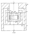
- Well structure 90 shown in FIGURE 4 includes housing 92 having internal recess 94 and flowby passages 96.
- High strength seat member 98 is divided into segments 100 which are positioned within recess 94 and locking ring 102 is formed into recesses 104 on the interior of segments 100 after the segments 100 have been positioned within housing recess 94. This is done by utilizing a non-high strength material for ring 102 so that it may be readily formed radially outward.
- High strength seat member 98 provides tapered landing shoulder 106 on which a hanger (not shown) may land.
- the material used for the high strength landing seat insert be of a high strength steel alloy which has the desired yield strength as set forth above and care should be taken to use materials which also function in the environment of the well bore.
- tool steel having the desired yield may be used provided that the well does not produce sulfur compounds such as hydrogen sulfide or sulfur dioxide.
- a corrosion resistant alloy be used such as a suitable Inconel alloy.
- the present invention provides a building block approach to solve the problem of the limited projected landing shoulder bearing area and spreads the shoulder load over much larger areas in the housing so that the loads are acceptable for the materials of the housing.
- differing loads can be accommodated merely by upgrading the material of the insert.
- This provides a single passive load shoulder that functions every time and eliminates complicated load sharing mechanisms.
Landscapes
- Life Sciences & Earth Sciences (AREA)
- Engineering & Computer Science (AREA)
- Geology (AREA)
- Mining & Mineral Resources (AREA)
- Physics & Mathematics (AREA)
- Environmental & Geological Engineering (AREA)
- Fluid Mechanics (AREA)
- General Life Sciences & Earth Sciences (AREA)
- Geochemistry & Mineralogy (AREA)
- Earth Drilling (AREA)
- Clamps And Clips (AREA)
- Pens And Brushes (AREA)
- Bridges Or Land Bridges (AREA)
- Supply Devices, Intensifiers, Converters, And Telemotors (AREA)
- Excavating Of Shafts Or Tunnels (AREA)
- Vehicle Body Suspensions (AREA)
- Massaging Devices (AREA)
- Drilling And Boring (AREA)
- Dowels (AREA)
- Chair Legs, Seat Parts, And Backrests (AREA)
- Saccharide Compounds (AREA)
- Optical Communication System (AREA)
Priority Applications (1)
| Application Number | Priority Date | Filing Date | Title |
|---|---|---|---|
| AT88311106T ATE93002T1 (de) | 1988-04-28 | 1988-11-24 | Bohrlochkopfgehaeuse und schulter zum setzen. |
Applications Claiming Priority (2)
| Application Number | Priority Date | Filing Date | Title |
|---|---|---|---|
| US187383 | 1988-04-28 | ||
| US07/187,383 US4826216A (en) | 1988-04-28 | 1988-04-28 | Well housing and landing shoulder |
Publications (3)
| Publication Number | Publication Date |
|---|---|
| EP0340365A2 true EP0340365A2 (de) | 1989-11-08 |
| EP0340365A3 EP0340365A3 (en) | 1990-06-20 |
| EP0340365B1 EP0340365B1 (de) | 1993-08-11 |
Family
ID=22688753
Family Applications (1)
| Application Number | Title | Priority Date | Filing Date |
|---|---|---|---|
| EP88311106A Expired - Lifetime EP0340365B1 (de) | 1988-04-28 | 1988-11-24 | Bohrlochkopfgehäuse und Schulter zum Setzen |
Country Status (10)
| Country | Link |
|---|---|
| US (1) | US4826216A (de) |
| EP (1) | EP0340365B1 (de) |
| JP (1) | JP2753006B2 (de) |
| AT (1) | ATE93002T1 (de) |
| AU (1) | AU627172B2 (de) |
| BR (1) | BR8901755A (de) |
| CA (1) | CA1317873C (de) |
| DE (1) | DE3883218T2 (de) |
| MX (1) | MX166358B (de) |
| NO (1) | NO302193B1 (de) |
Families Citing this family (3)
| Publication number | Priority date | Publication date | Assignee | Title |
|---|---|---|---|---|
| US4919460A (en) * | 1989-02-06 | 1990-04-24 | Vetco Gray Inc. | Wellhead casing hanger support mechanism |
| US5327966A (en) * | 1993-05-26 | 1994-07-12 | Dril-Quip, Inc. | Wellhead equipment |
| US5813470A (en) * | 1996-11-14 | 1998-09-29 | Abb Vetco Gray Inc. | Means for relieving load on stacked casing hangers |
Family Cites Families (10)
| Publication number | Priority date | Publication date | Assignee | Title |
|---|---|---|---|---|
| GB975209A (en) * | 1962-10-26 | 1964-11-11 | Otis Eng Co | Well head assembly |
| US3405956A (en) * | 1966-03-22 | 1968-10-15 | Gray Tool Co | Apparatus for mechanically keying parts to one another |
| US3438653A (en) * | 1966-10-14 | 1969-04-15 | Rockwell Mfg Co | Wellhead |
| US3902473A (en) * | 1972-05-03 | 1975-09-02 | Skuttle Mfg Co | Mobile or modular home humidifier |
| US3902743A (en) * | 1973-12-03 | 1975-09-02 | Fmc Corp | Full opening wellhead with retractile seat |
| US4528738A (en) * | 1981-10-29 | 1985-07-16 | Armco Inc. | Dual ring casing hanger |
| US4615544A (en) * | 1982-02-16 | 1986-10-07 | Smith International, Inc. | Subsea wellhead system |
| US4465133A (en) * | 1982-09-15 | 1984-08-14 | Combustion Engineering, Inc. | Casing hanger collet |
| US4595063A (en) * | 1983-09-26 | 1986-06-17 | Fmc Corporation | Subsea casing hanger suspension system |
| US4577686A (en) * | 1984-04-26 | 1986-03-25 | Vetco Offshore, Inc. | Mudline support hanger assembly |
-
1988
- 1988-04-28 US US07/187,383 patent/US4826216A/en not_active Expired - Lifetime
- 1988-11-17 CA CA000583340A patent/CA1317873C/en not_active Expired - Fee Related
- 1988-11-24 DE DE88311106T patent/DE3883218T2/de not_active Expired - Fee Related
- 1988-11-24 AT AT88311106T patent/ATE93002T1/de not_active IP Right Cessation
- 1988-11-24 EP EP88311106A patent/EP0340365B1/de not_active Expired - Lifetime
- 1988-12-02 JP JP63305888A patent/JP2753006B2/ja not_active Expired - Fee Related
-
1989
- 1989-01-23 MX MX014631A patent/MX166358B/es unknown
- 1989-02-07 NO NO890498A patent/NO302193B1/no not_active IP Right Cessation
- 1989-04-13 BR BR898901755A patent/BR8901755A/pt not_active IP Right Cessation
- 1989-04-24 AU AU33379/89A patent/AU627172B2/en not_active Ceased
Also Published As
| Publication number | Publication date |
|---|---|
| NO302193B1 (no) | 1998-02-02 |
| NO890498D0 (no) | 1989-02-07 |
| JP2753006B2 (ja) | 1998-05-18 |
| EP0340365B1 (de) | 1993-08-11 |
| MX166358B (es) | 1993-01-04 |
| BR8901755A (pt) | 1989-11-28 |
| JPH01275893A (ja) | 1989-11-06 |
| CA1317873C (en) | 1993-05-18 |
| US4826216A (en) | 1989-05-02 |
| AU627172B2 (en) | 1992-08-20 |
| ATE93002T1 (de) | 1993-08-15 |
| DE3883218T2 (de) | 1993-11-25 |
| DE3883218D1 (de) | 1993-09-16 |
| EP0340365A3 (en) | 1990-06-20 |
| NO890498L (no) | 1989-10-30 |
| AU3337989A (en) | 1989-11-02 |
Similar Documents
| Publication | Publication Date | Title |
|---|---|---|
| US4886121A (en) | Universal flexbowl wellhead and well completion method | |
| US7861789B2 (en) | Metal-to-metal seal for bridging hanger or tieback connection | |
| US6012519A (en) | Full bore tubing hanger system | |
| CA2060008C (en) | Tubing connector | |
| US4932472A (en) | Packoff with flexible section for casing hanger | |
| US5725056A (en) | Wellhead assembly with removable bowl adapter | |
| US20080093067A1 (en) | Wellhead isolation tool and method of fracturing a well | |
| US5279369A (en) | Tieback receptacle with upward and downward facing funnel sections | |
| US12006792B2 (en) | Snub friendly wellhead hanger | |
| EP0382677B1 (de) | Stützeinrichtung für Futterrohrhänger | |
| US4911244A (en) | Marine casing suspension apparatus | |
| GB2410514A (en) | Wellhead casing hanger | |
| US5094297A (en) | Casing weight set seal ring | |
| WO2018071446A1 (en) | One-trip hydraulic tool and hanger | |
| US3334923A (en) | Pipe handling mechanism | |
| US3311168A (en) | Well head assembly with means for effecting a preloaded seal | |
| EP0089798B1 (de) | Verrohrungsaufhängung | |
| US4826216A (en) | Well housing and landing shoulder | |
| US20020121368A1 (en) | Casing hanger system with capture feature | |
| US4515400A (en) | Wellhead assembly | |
| CA1127963A (en) | Vertically moored platform casing tieback | |
| US5341885A (en) | Internal tubing hanger lockdown | |
| US5865255A (en) | Full bore nipple and associated lock mandrel therefor | |
| EP0378040B1 (de) | Ein- und Ausbauwerkzeuge für Futterrohraufhänger | |
| CA1149735A (en) | Seal assembly releasing tool |
Legal Events
| Date | Code | Title | Description |
|---|---|---|---|
| PUAI | Public reference made under article 153(3) epc to a published international application that has entered the european phase |
Free format text: ORIGINAL CODE: 0009012 |
|
| AK | Designated contracting states |
Kind code of ref document: A2 Designated state(s): AT DE FR GB NL |
|
| PUAL | Search report despatched |
Free format text: ORIGINAL CODE: 0009013 |
|
| AK | Designated contracting states |
Kind code of ref document: A3 Designated state(s): AT DE FR GB NL |
|
| 17P | Request for examination filed |
Effective date: 19901122 |
|
| 17Q | First examination report despatched |
Effective date: 19920130 |
|
| RAP1 | Party data changed (applicant data changed or rights of an application transferred) |
Owner name: COOPER INDUSTRIES INC. |
|
| GRAA | (expected) grant |
Free format text: ORIGINAL CODE: 0009210 |
|
| AK | Designated contracting states |
Kind code of ref document: B1 Designated state(s): AT DE FR GB NL |
|
| REF | Corresponds to: |
Ref document number: 93002 Country of ref document: AT Date of ref document: 19930815 Kind code of ref document: T |
|
| REF | Corresponds to: |
Ref document number: 3883218 Country of ref document: DE Date of ref document: 19930916 |
|
| ET | Fr: translation filed | ||
| PLBE | No opposition filed within time limit |
Free format text: ORIGINAL CODE: 0009261 |
|
| STAA | Information on the status of an ep patent application or granted ep patent |
Free format text: STATUS: NO OPPOSITION FILED WITHIN TIME LIMIT |
|
| 26N | No opposition filed | ||
| PGFP | Annual fee paid to national office [announced via postgrant information from national office to epo] |
Ref country code: AT Payment date: 19951023 Year of fee payment: 8 |
|
| REG | Reference to a national code |
Ref country code: GB Ref legal event code: 732E |
|
| PG25 | Lapsed in a contracting state [announced via postgrant information from national office to epo] |
Ref country code: AT Effective date: 19961124 |
|
| PGFP | Annual fee paid to national office [announced via postgrant information from national office to epo] |
Ref country code: DE Payment date: 19971127 Year of fee payment: 10 |
|
| PG25 | Lapsed in a contracting state [announced via postgrant information from national office to epo] |
Ref country code: DE Free format text: LAPSE BECAUSE OF NON-PAYMENT OF DUE FEES Effective date: 19990901 |
|
| REG | Reference to a national code |
Ref country code: GB Ref legal event code: IF02 |
|
| PGFP | Annual fee paid to national office [announced via postgrant information from national office to epo] |
Ref country code: NL Payment date: 20021011 Year of fee payment: 15 |
|
| PG25 | Lapsed in a contracting state [announced via postgrant information from national office to epo] |
Ref country code: NL Free format text: LAPSE BECAUSE OF NON-PAYMENT OF DUE FEES Effective date: 20040601 |
|
| NLV4 | Nl: lapsed or anulled due to non-payment of the annual fee |
Effective date: 20040601 |
|
| PGFP | Annual fee paid to national office [announced via postgrant information from national office to epo] |
Ref country code: FR Payment date: 20071105 Year of fee payment: 20 Ref country code: GB Payment date: 20071005 Year of fee payment: 20 |
|
| REG | Reference to a national code |
Ref country code: GB Ref legal event code: PE20 Expiry date: 20081123 |
|
| PG25 | Lapsed in a contracting state [announced via postgrant information from national office to epo] |
Ref country code: GB Free format text: LAPSE BECAUSE OF EXPIRATION OF PROTECTION Effective date: 20081123 |