EP0340367B1 - Système d'alimentation du moule dans une fonderie - Google Patents
Système d'alimentation du moule dans une fonderie Download PDFInfo
- Publication number
- EP0340367B1 EP0340367B1 EP19880401113 EP88401113A EP0340367B1 EP 0340367 B1 EP0340367 B1 EP 0340367B1 EP 19880401113 EP19880401113 EP 19880401113 EP 88401113 A EP88401113 A EP 88401113A EP 0340367 B1 EP0340367 B1 EP 0340367B1
- Authority
- EP
- European Patent Office
- Prior art keywords
- skin
- conduit
- strainer
- restraining
- cavity
- Prior art date
- Legal status (The legal status is an assumption and is not a legal conclusion. Google has not performed a legal analysis and makes no representation as to the accuracy of the status listed.)
- Expired
Links
- 230000000452 restraining effect Effects 0.000 claims 26
- 239000002184 metal Substances 0.000 claims 13
- 230000000903 blocking effect Effects 0.000 claims 7
- 238000005266 casting Methods 0.000 claims 6
- 239000004606 Fillers/Extenders Substances 0.000 claims 4
- 239000000203 mixture Substances 0.000 claims 4
- 239000011819 refractory material Substances 0.000 claims 4
- 230000000694 effects Effects 0.000 claims 3
- 230000003628 erosive effect Effects 0.000 claims 3
- 230000005484 gravity Effects 0.000 claims 3
- 239000000463 material Substances 0.000 claims 2
- 230000013011 mating Effects 0.000 claims 1
Images






Classifications
-
- B—PERFORMING OPERATIONS; TRANSPORTING
- B22—CASTING; POWDER METALLURGY
- B22C—FOUNDRY MOULDING
- B22C9/00—Moulds or cores; Moulding processes
- B22C9/08—Features with respect to supply of molten metal, e.g. ingates, circular gates, skim gates
Definitions
- the invention relates to a gravity poured foundry mold having a gating system according to the first portion of claim 1.
- the flow of metal in a gravity poured mold is controlled by a gating system so as to produce one or more castings.
- the gating system if properly designed, promotes good directional solidification of the casting or castings produced with that mold.
- Such molds may be made, for example, of sand, of graphite, or of a metallic-based material. They also may be based on any other material or combination thereof, so long as the metal being poured is compatible with the refractoriness of those materials and with the refractoriness of other materials used in the mold.
- Said US patent discloses a gravity poured foundry mold having a gating system and at least one complete mold casting cavity, in which said gating system establishing necessary flow paths between an open outside of the mold and said cavity and comprising at least one conduit forming one of said flow paths, said conduit being open on opposite ends thereof and extending directly from an outer surface of said mold to a surface of said cavity, said conduit comprising means for receiving molten metal and guiding said molten metal directly toward said cavity such that, during pouring, all molten metal passing through said conduit flows directly toward said cavity, and said gating system further comprising straining means interposed between said conduit and said cavity.
- Figure 1 shows a mold in its pouring position comprising one mold casting cavity 1, and an embodiment of a skin-strainer 2 located somewhere along the top 3 of the mold casting cavity surface and preferably being located at those points requiring a traditional riser or feeder.
- a conduit 5 which, in the illustrated embodiment, is a sprue-feeder extending to the top surface 4 of the mold.
- the sprue-feeder 5 communicates with mold casting cavity 1 through apertures 6 in skin-strainer 2, the apertures 6 collectively comprising the total passage cross-sectional area of the skin-strainer.
- a skin-strainer 2 may be located along the bottom or side surfaces of the mold casting cavity, the most natural and advantageous location is the surface of the casting cavity 1 which is on top when the mold is in pouring position.
- the skin-strainer 2 is firmly held in position at the lower end of the sprue-feeder 5 using retaining means 7 embedded in the top of part 8 of the mold.
- the top of part 8 of the mold is made of bonded sand
- the skin-strainer 2 is ceramic
- the retaining means 7 is metallic.
- Other materials may be used, provided the refractoriness of those materials is compatible with the temperature of the metal being poured.
- the apertures 6 may advantageously have tapered side walls.
- a mold having a gating system comprising one or more skin-strainers 2 generally allows for the production of good quality castings at a lower cost than other traditional gating systems.
- choosing the size of the apertures 6 and the total passage cross-sectional area of the skin-strainer presents a conflict.
- the apertures must be sufficiently small to allow for easy choking of the sprue-feeder during pouring and to avoid the passing of melt inclusions through the apertures 6 into the mold casting cavity.
- the passage area must be large enough to allow not only for good filling of the cavity but also, and when necessary, for good feeding of the casting during its solidification.
- the invention relates to a gravity poured foundry mold as disclosed in the above mentioned prior art and characterized in that :
- the current application discloses three generic types of restraining means for assisting the choking of the conduit 5 by restraining the flow of metal through the total cross-sectional passage area at at least one point between the outside surface of the mold and the mold casting cavity.
- the restaint is temporary and promotes the choking of the conduit during pouring.
- some structural means are provided for assuring proper feeding of the casting.
- the restraining means may take the generic forms of a cover, a restraining floating piece, and a non-floating restraining piece. Each of these generic types of restraining means may be used by itself or in combination with the others, and more than one restraining floating piece and non-floating restraining piece may be used in association with the same skin-strainer.
- the cover comprises at least a main body and a handle, the main body being insertable into the conduit and having a bottom surface configured to close off, at least partially, the total flow area available for the passage of molten metal from the conduit 5 into the cavity 1.
- the combined effects of the diminished flow area and the volume of the cover facilitate the choking of the conduit 5.
- the handle is used to remove the cover from the conduit 5, thereby permitting the flow of molten metal into the mold casting cavity 1 through an increased flow area.
- the conduit may be kept choked by increasing, as necessary, the flow rate of metal being poured up to the moment that the mold casting cavity is full.
- Restraining floating pieces also may be used in order to temporarily restrict the available flow area from the conduit into the cavity.
- the restraining floating pieces may be used instead of a cover or, in the alternative, may be used together with a cover.
- One or more restraining floating pieces are initially disposed in the aperture means between the conduit and the cavity.
- a restraining floating piece does not completely block the flow area of any given aperture.
- the restraining floating piece will float, thereby restoring the original open area of the aperture in which the piece had been disposed, such that the entire original area is available for proper feeding of the casting.
- the restraining floating piece When one or more restraining floating pieces is used simultaneously with a cover, the restraining floating piece may be disposed in an aperture covered by the cover or in an aperture not covered by the cover, or a restraining floating piece may be disposed in both such locations.
- the casting surface i.e., the surface of the mold casting cavity
- Similar modifications may be made when also using the restraining means according to the current invention. Examples of such modifications are illustrated in Figures 2 and 3.
- Figure 2 shows a skin-strainer 2 located along a modified mold casting cavity surface 9, which defines a volume modification 10 of the mold casting cavity 1.
- the volume modification extends upwardly.
- Figure 3 shows a similar volume modification which extends sideways.
- the advantages achieved by using restraining means according to the current invention may be realized in the absence of a skin-strainer.
- the use of the restraining means makes the application of a skin-strainer and its advantages more universal within foundry molding practice.
- a "metal” is a pure metal or an alloy.
- a "melt” is a batch of molten metal.
- a “casting” is a metal object cast to a desired shape by pouring or injecting, or both, liquid metal into a mold, as distinct from a metal object shaped by a mechanical process.
- a “gravity mold” is any foundry mold designed to be filled with molten metal only under the effect of gravity. Most usually, once the different parts of a gravity mold are made, the position in which the mold is closed, i.e., the position in which the different parts of the mold are assembled, is the same position in which the mold is poured. Nevertheless, and as is well known, a gravity mold may also be closed in one position and then rotated into a different pouring position.
- An “inclusion” is a particle of impurity, usually non-metallic and not dissolved in the molten metal.
- An impurity is generally lighter than the metal and is desirably separated from the metal before the metal reaches the mold casting cavity.
- a "sprue” is the first conduit, usually vertical in the case of a traditional gravity mold, through which the metal enters the mold.
- a “riser” or “feeder” is a reservoir connected to the casting so as to provide liquid metal to the casting during solidifcation, to offset shrinkage which takes place when the casting solidifies.
- “Fettling”, also called “foundry finishing operation” or just “finishing” is the process of removing the complete gating system and flashes from the casting after the mold is poured and shaked out, and the carrying out of any necessary operation such that the casting is dimensioned and shaped in accordance with a casting drawing, sample, pattern or any agreement with the customer ordering the casting.
- the "mold casting cavity” is the empty part of the mold which corresponds to the complete casting to be produced within that mold, the casting shape being defined in accordance with a sample, a casting drawing, a pattern or any other procedure.
- a modification of the casting surface, and consequently of the casting and of the corresponding mold casting cavity may be introduced in the foundry for different reasons. Such modifications may be such as either are accepted by the casting customer or eliminated by the foundry at the fettling stage or later at the machine shop.
- the correspondingly modified mold casting cavity is the one described in the disclosure and claims herein by the phrase "mold casting cavity" or just "cavity".
- a "sprue-feeder” is a conduit acting both as a sprue and as a feeder. Previously, a sprue-feeder has been considered unsuitable for producing a good quality casting. However, a good quality casting may be made using a sprue-feeder as disclosed herein.
- treating system includes the traditional complete assembly of sprues, runners, ingates, vents, flow-offs, feeders and the like necessary to pour and produce a good casting.
- Restraining means is means cooperating with an opening to restrain (i.e., to block or restrict) flow through an opening, and comprising one or more elements distinct from the material in which the opening is found.
- the degree of restraint may be total or less than total.
- a “skin-strainer” is a straining means which includes a skin-strainer as disclosed herein and as disclosed generically and in several specific forms in U.S. Patent 4,154,289. In that U.S. patent, the skin-strainer is identified in the several views by any of reference numerals 20, 34 and 35.
- Feeing is the effect produced by a feeder.
- Directional solidification describes the solidification of molten metal in a mold casting cavity such that feeding metal is always available for that portion of the casting that is just solidifying.
- Refractoriness is the ability of a material to withstand high temperatures as, for example, contact with molten metal.
- the refractoriness of a material is a relative term and depends upon the metal being melted and poured to produce castings, as different foundry metals melt at temperatures over a widely varying range.
- Refractory materials When a metal having a low melting point is being poured, a wide variety of materials exhibit refractoriness, including other metals having higher melting points. As the melting point of the metal being poured increases, the range of materials exhibiting refractoriness is reduced and may ultimately include only some metals properly protected with an adequate refractory wash or one of those materials usually referred to as "refractory materials" or just ceramics, including all solid industrial materials that are neither metallic nor organic, which are highly heat resistant and have low thermal conductivity, whether in a granulated or powdered form. Refractory materials may be given many different shapes by using a bond that may be mechanical, physical, chemical, sintered, a combination of the above, or any other type of bond.
- a skin-strainer cover including a body 11, the bottom surface of the body 11 being in contact with the top surface of skin-strainer 2 so as to block a fraction of the total cross-sectional passage area formed by the apertures of the skin-strainer. Apertures 12 are covered by the skin-strainer cover, while additional apertures 6 are not covered by the skin-strainer cover.
- the skin-strainer cover body 11 may advantageously be made of a refractory material.
- a handling means is partially embedded in the body 11 and comprises an anchoring form 13, a connecting bar 14 and a handle 15.
- the handling means can be made by forging, welding or any other suitable and known procedure.
- an enlargement 16 may be formed in sprue-feeder 5 to provide an additional volume than would otherwise be provided by the lesser diameter of the lower portion of the sprue-feeder. Also, such an enlargement 16 makes it easier to choke sprue-feeder 5.
- molten metal is poured either into the enlargement 16, or directly into sprue-feeder 5, quickly enough to choke the sprue-feeder.
- the first metal begins to pass through apertures 6 into cavity 1.
- the skin-strainer cover is lifted and removed from the sprue-feeder.
- pouring is increased in order to keep the sprue-feeder 5 choked.
- the pouring continues until the molten metal starts rising, thereby indicating that the mold casting cavity is full. Pouring is then stopped.
- the necessary difference of metal is added.
- venting of the cavity 1 cannot be accomplished properly through the choked sprue-feeder 5. Therefore, any known venting method should be used such that the gases in the mold casting cavity 1 are pushed outside while the molten metal is rising in the cavity.
- Figure 5 shows a second embodiment of a skin-strainer cover which provides improved mating between skin-strainer cover body 11 and skin-strainer 2.
- the bottom surface of the skin-strainer cover body 11 is provided with a plurality of plug-like penetrations 17 which fit within those apertures 12 of the skin-strainer which are blocked by the skin-strainer cover.
- the shape of the apertures of the skin-strainer 2 may be modified to promote the mating of the surfaces, for example, by modifying the taper of the apertures 12 or defining any other suitable shape for the apertures 12.
- Figure 6 illustrates a third embodiment in which the upper surface of the skin-strainer 2 does not contact the bottom surface of the skin-strainer body 11.
- This embodiment illustrates the fact that, with well-fitting penetrations 17, it no longer is necessary to have such contact between the upper surface of the skin-strainer 2 and the lower surface of the body 11.
- the downward force applied on the skin-strainer cover 11 and against the skin-strainer 2 must balance the upward force on the skin-strainer cover resulting from the molten metal until the moment that the skin-strainer cover is lifted.
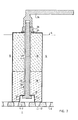
- Figure 7 illustrates a fourth embodiment of a skin-strainer cover according to the invention in which the skin-strainer cover is formed of standardized parts.
- the body of the skin-strainer cover comprises at least a bottom standard part 18 and, if required by the length of the sprue-feeder 5, also by one or more auxiliary cover extension parts 19.
- a longitudinal passage 20 is formed in the bottom standard part 18 and communicates with a recess 21 formed at the bottom of the bottom standard part 18.
- Anchoring form 13 of a standardized connecting bar 22 is disposed in recess 21.
- the standard connecting bar 22 passes through the passage 20 and through corresponding passages 23 of any auxiliary cover standard extension parts 19 that may be present.
- a standardized handle 24 is connected to the standardized connecting bar 22 as, for example, by using a threaded fastener.
- the threaded fastener may be formed by a thread at the upper end of the standardized connecting bar 22, a washer 25 and a nut 26, this threaded fastener additionally permitting the tightening of the entire skin-strainer cover as a whole.
- the anchoring form 13 may be square or hexagonal in cross-section, and recess 21 may desirably be large enough to permit the introduction into recess 21 of a tube wrench for facilitating the tightening of the skin-strainer cover as a hole. Following the assembly of the skin-strainer cover, and if recess 21 is larger than necessary for accommodating the anchoring form 13, the recess 21 may be filled with a refractory mix 27 so as to avoid contact between the molten metal and the anchoring form 13 during the stage when the skin-strainer cover is lifted upwardly within the sprue-feeder 5.
- the bottom standard part 18 and auxiliary extension standard parts 19 may be made of any suitable refractory material, applying any known manufacturing procedure for making parts with such materials.
- the metallic standard parts also may be made by known procedures.
- the skin-strainer cover may be held in place against the skin-strainer 2 during pouring by hand and lifted at the right moment during pouring.
- it may be easier or even necessary to provide other means for lifting to assure both proper initial holding in place during pouring and the subsequent lifting operation.
- the skin-strainer cover is in contact with the molten metal for a comparatively short time, usually a matter of seconds. Accordingly, if the body of the skin-strainer cover is made of a material with a sufficiently high degree of refractoriness, the cover typically will be reusable for the pouring of several or even many molds.
- the total passage cross-sectional area of the skin-strainer should be at least the minimum necessary both for adequate filling of the cavity 1 during pouring and also for adequate feeding of the casting following pouring.
- one or more restraining floating pieces, or one or more non-floating restraining pieces, or both are employed as restraining means.
- Such restraining means partially block the apertures in which they are disposed, thereby creating a restricted cross-sectional passage area presented by the assembly of the skin-strainer and the restraining pieces disposed therein. Accordingly, the total passage cross-sectional area of the skin-strainer 2 itself, considered alone, will be greater than the minimum necessary for adequate filling of the cavity 1.
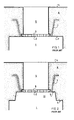
- Figures 8A and 8B respectively show vertical and horizontal cross-sections of restraining floating piece 28 according to the current invention.
- the restraining floating piece 28 is disposed in aperture 6 of skin-strainer 2 and has a lower surface 30, an upper surface 31 and an external lateral surface 32.
- Passage 29, formed in the restraining floating piece communicates sprue-feeder 5 with mold casting cavity 1. Because of the presence of passage 29, the restraining floating piece only partially blocks the aperture 6 of skin-strainer 2.
- the restraining floating piece is shown slightly elevated above its actual position during pouring, at which time lateral surface 32 contacts the lateral wall of aperture 6.
- surface 30 will be lower than lower surface 33 of skin-strainer 2
- surface 31 of the restraining floating piece will be higher than upper surface 34 of skin-strainer 2.
- Recesses 35 are formed around the lower portion of the restraining floating piece and are interrupted by tooth-like projections 37, hereinafter called teeth.
- the radially-outer surfaces of the teeth 37 are coincident with the lateral surface 32 of the restraining floating piece and therefore also contact the wall of the aperture 6.
- three such teeth 37 are provided.
- the upper surfaces 36 of the recesses 35 are disposed at a level above that of lower surface 33 of skin-strainer 2 and lower than that of upper surface 34 of skin-strainer 2 when the restraining floating piece is in its pouring position.
- the aperture 6 is shown as circular, the restraining floating piece 28 is generally annular, and the bottom surface 33 of skin-strainer 2 is flat.
- the restraining floating piece serves to restrict the area of apertures 6, reducing the now available cross-sectional area to that created by passage 29.
- the restraining floating piece 28 floats, thereby increasing the effective cross-sectional area that is now available for feeding of the casting.
- restraining floating piece 28 The ability of restraining floating piece 28 to float depends upon a number of factors including the weight of the restraining floating piece, the buoyant force acting on the restraining floating piece that results from the weight of the molten metal displaced thereby under the Pascal principle, and the fact that a portion of surface 32 is in contact with wall 6 and therefore is not initially available for being urged upwardly by molten metal in the cavity 1 after the cavity 1 is filled.
- the level of surface 36 may be made as near as possible to that of surface 34, the number of teeth 37 may be made as few as possible, the slope of the wall of aperture 6 may be as nearly vertical as possible, the level of surface 30 may be as low as necessary or as permitted by the mold casting cavity 1, and the level of surface 31 may be as high as necessary.
- the weight of the restraining floating piece will be a function of its composition.
- Figures 9A and 9B respectively show vertical and horizontal cross-sections of a second embodiment of a restraining floating piece according to the current invention.
- the restraining floating piece is configured such that a number of passages 38 are formed when the piece is inserted into the aperture 6, the passages extending along the entire height of the external surface 32 of the restraining floating piece, the passages communicating the sprue-feeder 5 and the cavity 1.
- the restraining floating piece is shown slightly elevated above its pouring position for purposes of illustration.
- Bottom surface 30 of the restraining floating piece is disposed at a level below that of bottom surface 33 of skin-strainer 2.
- Upper surface 31 of the restraining floating piece is shown disposed at a level above that of top surface 34 of skin-strainer 2, but it may be desirable for surface 31 and surface 34 to be coincident, depending upon any desired degree of blockage that may be provided by a cover, if a cover is used to cover that particular restraining floating piece.
- Figures 10A and 10B respectively show vertical and horizontal cross-sections of a third embodiment of a restraining floating piece according to the current invention. Also shown is a second embodiment of a skin-strainer.
- the restricted passage cross-sectional area of the aperture 6 is provided by grooves 39 formed in the sidewall of the skin-strainer aperture, passing entirely through the thickness of the skin-strainer. Accordingly, no passages need be incorporated into the construction of the restraining floating piece itself.
- the restraining floating piece is shown for purposes of illustration elevated somewhat above its position for pouring. In the pouring position, the bottom surface 30 of the restraining floating piece is at a level below the bottom surface 33 of skin-strainer 2, and surface 31 is disposed at a level lower than that of surface 34.
- Figure 11 illustrates the use of two restraining floating pieces in combination with a skin-strainer cover.
- any number of restraining floating pieces may be used, and more than one embodiment may be used at the same time.
- the restraining floating pieces may be used without the assistance of a skin-strainer cover.
- a restraining floating piece 40 disposed in an aperture 12 which is covered by the skin-strainer cover body 11 and a restraining floating piece 28 disposed in an aperture 6 of skin-strainer 2 which is not covered by skin-strainer cover body 11.
- Pieces 28 and 40 are shown as modifications of the embodiment of Figures 8A and 8B.
- Piece 28 is modified by raising its lower surface 30 above the bottom surface 33 of the skin-strainer, whereas the piece 40 is modified such that its upper surface 31 is below the level of top surface 34 of skin-strainer 2.
- passage 29 of piece 28 will be available for communicating sprue-feeder 5 with cavity 1 immediately upon the initiation of pouring, whereas passage 29 of piece 40 will not be available for such communication until the skin-strainer cover is lifted.
- the upper surface 31 of the one or more restraining floating pieces disposed in the apertures 12 covered by the skin-strainer may also be disposed at the level of top surface 34 of the skin-strainer or even above the level of surface 34 of the skin-strainer so long as the bottom of the skin-strainer cover body 11 is effective to cover the holes 29.
- the upper surfaces 31 of the restraining floating pieces disposed in the apertures 12 may lie in a common plane with the bottom of the cover body 11.
- Figure 12 illustrates an alternative in which the available volume in sprue-feeder 5 is increased by decreasing the size of skin-strainer cover body 11 without decreasing the number of apertures that are covered by the body 11.
- restraining floating pieces 40 are disposed with their upper surfaces 31 even with surface 34, and the size of the body 11 is just sufficient to block the passages 29.
- FIG 11 there is shown a modification of the restraining floating pieces in which the bottom surfaces 30 thereof are disposed at a level above that of bottom surface 33 of skin-strainer 2.
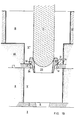
- Figure 13 shows a fifth embodiment of a cover body 11, in the form of a skin-plug, a third embodiment of a skin-strainer 2, and a fourth embodiment of a restraining floating piece.
- the skin-strainer 2 has a single aperture 12 which receives restraining floating piece 40.
- recesses 35 are interrupted by teeth 37, but upper surfaces 36 of the recesses are inclined for somewhat increasing the volume of the restraining floating piece and its floatability.
- the restraining floating piece is illustrated somewhat elevated above its position for pouring. In the pouring position, lateral surface 32 contacts the wall of aperture 12.
- a laterally-extending expansion 41 having a lower surface 42 disposed at a level above the upper surface 34 of skin-strainer 2.
- Surface 41 enhances the floatability of restraining floating piece 40 by providing an additional surface on which may act the metalstatic pressure of molten metal in sprue-feeder 5.
- Restraining floating piece 40 is provided with a passage 29, a portion of which is spherical and has a radius R as shown.
- the remainder of the passage 29 may advantageously be conic, as shown at 44.
- the skin-strainer cover comprises a skin-strainer cover body 11, bottom 45 of which is spherical and has a radius r which is as close as practical to the radius R in order to obtain good mating of surfaces 43 and 45.
- the center of curvature C of the radii R and r may be disposed at a level above that of upper surface 31 of the restraining floating piece.
- Figure 13 Also shown in Figure 13, and further complementing the mold, is an optional sprue-feeder extender 46 for increasing the height of the sprue-feeder above the top surface 4 of the mold, when desired.
- Figure 13 further shows an optional sprue-feeder expander 47 for increasing the volume of available molten metal in the sprue-feeder, when desired.
- sprue-feeder extender 46 and sprue-feeder expander 47 may be made integrally as one piece, or sprue-feeder expander 47 may be placed directly on the top surface 4 of the mold when the sprue-feeder extender 46 is not desired.
- Known foundry practice may be used to ensure that the various contacting surfaces of the mold, extender 46 and expander 47 are properly sealed in order to avoid leakage of molten metal.
- Modifications of the restraining floating piece 40 also are possible. For example, surface 42 may be lowered and made to rest on surface 34 whenever needed to avoid a wedge effect between the surface of aperture 12 of the skin-strainer 2 and the lateral surface 32 of the restraining floating piece 40. This modification may be accomplished without loosing the floatability of the restraining floating piece 40 by making appropriate adjustments of its dimensions.
- the skin-strainer cover body 11 completely blocks the passage 29. Accordingly, no molten metal passes into the mold casting cavity 1 before the skin-strainer cover is lifted.
- This embodiment makes it quite easy for pourers of lower skill to accomplish choking of sprue-feeder 5. It also provides a container of sufficient size that it may be filled, even before lifting of the skin-strainer cover, with a volume of metal that is sufficient to fill the mold casting cavity 1, the other parts of the gating system such as ventings or traditional feeders, and the sprue-feeder 5 itself with the necessary amount of metal for filling the cavity and feeding the corresponding casting. A mark may be placed before pouring on the sprue-feeder expander 47 for indicating a level corresponding to that volume.
- the skin-strainer cover removed and the cavity 1 filled, the metalstatic pressure of the molten metal acts on surfaces 30, a portion of surface 32, and on the walls of recesses 35 to produce a net upward balance of forces, thereby causing the restraining float piece 40 to float.
- the piece 40 when it floats, also automatically protects, to some degree, the upper surface of the molten metal in the sprue-feeder 5.
- the exit of the restraining floating piece 40 from the aperture 12 restores the original total passage cross-sectional area of the skin-strainer for proper feeding of the mold casting cavity 1 from the sprue-feeder 5.
- the cavity 1 can be filled without additional human intervention, an important advantage in assuring proper operation.
- this embodiment of a skin-strainer cover body 11 may be just called a skin-plug, inasmuch as it comprises a plug placed near the level of the skin of the casting.
- the embodiment of Figure 13 may be used without the skin-strainer cover, provided that the passage 29 and sprue-feeder 5 are such that the sprue-feeder may be choked easily.
- the spherical surface 43 of the restraining floating piece is not necessary and may be replaced if desired by an extension of the conic surface 44.
- sprue-feeder expander 47 typically will be eliminated.
- the sprue-feeder extender 46 may be kept up if necessary for proper feeding of the mold casting cavity 1.
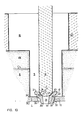
- Figure 14 shows a fourth embodiment of a skin-strainer and a fifth embodiment of a restraining floating piece.
- the embodiment is similar to that of Figure 13, except that the lateral wall of restraining floating piece 40 comprises a spherical segment 48 and a conic section 49, and the wall of aperture 12 of the skin-strainer is correspondingly formed with a spherical segment 50 and a conic segment 51.
- the various embodiments disclosed herein may be made of standardized parts which are usable in various combinations, thereby increasing the versatility of the system.
- the cover of the embodiments of Figures 13 and 14 may be made of standardized parts and constructed similarly to the cover illustrated in Figure 7, such that the skin-strainer cover body 11 becomes a skin-strainer cover standard bottom part 18.
- Figure 14 has been further simplified by not showing any necessary skin-strainer retaining means 7 as shown in Figures 1-3.
- Figure 14 provides even further versatility with standardized parts, arising from the spherical nature of the matings both between skin-plug 18 and restraining floating piece 40, and between restraining floating piece 40 and skin-strainer 2.
- restraining floating piece 40 be used alone or in combination with a skin-plug as shown in Figure 14, but the skin-strainer 2 may be used in combination with the skin-plug 18 without the interposition of a restraining floating piece 40.
- a larger skin-plug 18 will be used having a greater radius of curvature r, such that the surface 45 will mate properly with spherical surface 50 on skin-strainer 2.
- Figure 15 shows a sixth embodiment of a cover, a sixth embodiment of a restraining floating piece, a further overall embodiment according to the current invention which is made possible when the top of part 8 of the mold is made of a material such as a sand mold aggregate.
- a skin-strainer is not present, but a strainer means is provided in the form of sprue-feeder collar 52 defining a sprue-feeder restricted passage 53, the sprue-feeder collar 52 being formed as part of the top part 8.
- the aperture formed by restricted passage 53 will be larger than an aperture available in a skin strainer. Accordingly, the restraining floating piece must be correspondingly larger, but is still provided with a lateral surface having a spherical segment 48 and a conic segment 49.
- the sprue-feeder collar 52 is substantially thicker than skin-strainer 2 and is provided with a spherical surface 54 and a conic surface 55.
- the lateral dimension of the sprue-feeder 5 also is larger. It terminates in a sloping surface 56 which is connected to a lateral wall of the sprue-feeder 5 at a radius 57 for avoiding a sharp corner.
- Collar 52 is formed of a material much less resistant to the forces it will encounter than prefabricated skin-strainer 2 which, depending upon its size and on the metal poured, is typically made of ceramic, metal or a combination of the two. Accordingly, in the embodiment of Figure 15, the collar 52 must be made sufficiently resistant and therefore is thicker than a skin-strainer and is provided with slope 56 and radius 57. However, the thicker sprue-feeder collar 52 is less advantageous for proper feeding of the casting once the mold is poured and the metal still liquid. To compensate, the aperture 53 is typically larger than that found in an embodiment such as Figure 14.
- the size of the sprue-feeder 5 also is increased in order that the metal in aperture 53 solidifies later than that part of the casting which must be fed by sprue-feeder 5. It should be noted that the provision of a larger aperture 53 and larger sprue-feeder 5 imply that more molten metal must be used and more fettling work must be done.
- the strength of collar 52 may be increased, although not easily, by using an adequate metallic reinforcing armature which can be made following known practices in the foundry molding art.
- the restraining floating piece may be used without the skin-plug, or a larger skin plug may be used without a restraining floating piece.
- FIG. 15 Also shown in Figure 15 is the presence of one or more optional channels 45′ on the bottom 45 of the skin-plug.
- This embodiment may also be used in Figure 14.
- the channel or channels 45′ allow for some molten metal to pass form the sprue-feeder 5 into the cavity 1 from the start of pouring but before the cover is lifted.
- the channel or channels 45′ are not so large as to hinder adequate choking of the sprue-feeder.
- channels 45′ are possible.
- they may be formed in surfaces 43, 50 or 54 in Figures 14 and 15.
- the restraining floating piece should be made of any material having an adequate refractoriness and a lower density than the molten metal being poured, so that the restrainng floating piece can withstand the impact of the molten metal, erosion, temperature, the weight of the skin-strainer cover if used, and the like, and also such that the piece may float once the mold casting cavity is full.
- a restraining floating piece will be made of a sintered refractory material.
- the sprue-feeder extender 46 and sprue-feeder expander 47 may be made of any material whose refractoriness and resistance are compatible with such applications.
- sprue-feeder extender 46 will be made of bonded molding sand, and may advantageously be used in combination with exothermic materials for that part of the extender which will remain in contact with the metal after the mold is poured.
- Sprue-feeder exapnder 47 is preferably made of sintered refractory material. Because the amount of time it will remain in contact with the molten metal will typically be very short, the expander may be reused many times.
- a characteristic of a restraining floating piece is that it floats free of an aperture in which it is disposed once its restraining function is over, thereby enlarging the effective area available for feeding the casting.
- a-restraining piece which does not float but remains disposed in an aperture, yet nevertheless enhances feeding.
- Such a piece will be called a non-floating restraining piece. If the piece 28 illustrated in Figures 8A and 8B were made, for example, of a material sufficiently dense that it will not float, the piece will become a non-floating restraining piece. As will be described later, additional modification may be made to the embodiment shown in Figures 8A and 8B to further assist in the prevention of floating.
- recesses 35 will fill with molten metal and form a hot reservoir or heat source around passage 29.
- the reservoir 35 is thermally-adjacent the passage 29, by which it is meant that the composition and structure of the non-floating restraining piece is such that the hot metal in reservoir 35 is effective to keep the metal hot in passage 29.
- the heat source in recess 35 achieves the desired effect that molten metal in passage 29 remains liquid for a longer period of time and, consequently, the ability of passage 29 to feed the casting is enhanced. With this enhancing, passage 29 tends to be equivalent to a substantially larger passage and closer to the aperture 6.
- the passage 29 still retains its other advantages of facilitating choking of the sprue-feeder during pouring and further provides for easier fettling (for example, the type of metal and casting shape may allow for a sprue-feeder that can be knocked off more easily).
- Additional modificatins that may be made to the structures shown in Figures 8A and 8B to diminish the capacity for floating or otherwise improving the operation of the non-floating restraining piece include enlarging the recesses 35 inwardly toward passage 29 (which also increases the heat source), dimensioning the overall height of the piece 28 such that the passage 29 is shortened, adjusting the slopes of the wall of aperture 6 and of surface 32, eliminating the teeth 37 (which also increases the heat source), and providing a fresh refractory wash on surface 32 and on the wall of skin-strainer aperture 6 between the surface 32 and the wall of aperture 6 in order to cause surface 32 and the wall to stick together.
- the various embodiments according to the current invention may be standardized, thereby greatly enhancing the ease of use, accuracy and confidence with which they may be used.
- standardization there may be made available to foundries variously sized, prefabricated, interchangeable and correlated skin-strainers, restraining floating pieces, non-floating restraining pieces and covers, thereby making available corresponding elements that adequately match with each other.
- the prefabrication and standardization also may be extended to any auxiliary means or element necessary or useful for making easier the application of those restraining means already described, or any other.
- Such standardization could mean establishing: first, a unique pattern or perhaps several patterns of matching shapes between the restraining elements, which patterns could be similar to those disclosed herein or any other; second, a unique pattern or perhaps several patterns of open area shapes for the skin-strainers and the restraining pieces; third, elements permitting adequate variation of pouring rates, i.e., of open areas; and fourth, suitable sets of different sizes of, for example, skin-strainers, restraining pieces and covers. Most such patterns will be adequate for pouring any kind of metal, but some could be specialized for example for pouring steels and irons, some others for pouring aluminum alloys in particular or non-ferrous alloys in general.
- the standardization also could include a consideration of using several different materials in manufacturing the various elements.
- All of the skin-strainer covers considered in the standardization could be configured such that any skin-strainer cover of the set may be used with a corresponding skin-strainer or with a corresponding interposed restraining piece.
- FIG. 16 Shown in Figure 16 is a collar edge 58 which is standardized, prefabricated and typically made of ceramic. Collar edge 58 has an aperture 53, the sidewall of which comprises spherical segment 54 and conic segment 55 which generally follow and correspond to the same surfaces of collar 52 as shown in Figure 15. Also as shown, the collar edge 58 contains upper and lower surfaces that match with surfaces 3 and 56, forming extensions of those surfaces. Collar edge 58 has an outside back surface 59 adequate to firmly connect and support the collar edge 58 to the remaining part of the collar 52.
- the collar edge 58 may be placed around the pattern for the passage 53 and underneath the pattern for the sprue-feeder 5. Molding sand will then be rammed against the casting pattern, against the collar edge 58 and against the pattern for the sprue-feeder 5.
- the collar edge 58 presents surfaces 54 and 55 that are harder and smoother than the corresponding surfaces illustrated in Figure 15, it will assure a more accurate matching with any restraining means as, for example, a skin-plug, a restraining floating piece, a non-floating restraining piece, and the like.
- the gating system described in this specification is advantageously compatible with the performance of in-mold metallurgical treatments.
- Such treatments involve the use of one or several metallurgical treatment products which must be in contact with the molten metal shortly before the molten metal reaches the mold casting cavity. It is known in the art to place such products somewhere in the filling section of a traditional gating system, usually formed by the assembly of sprues, channels and ingates, in such a way that the molten metal is automatically treated as it flows toward the mold casting cavity.
- such a metallurgical treatment product or products may easily be placed on surfaces 34 or 31, or in sprue-feeder enlargement 16 on the top surface of sprue-feeder extension 46 or in a lateral chamber specially formed off of sprue-feeder 5 during the molding stage, either in the top part 8 of the mold or in sprue-feeder extender 46, or in several or all of such locations, or in any other location.
- sprue-feeder 5 overlaps the mold casting cavity contour surface such that the sprue-feeder intersects the cavity 1 at an edge of the cavity and a portion of the cross-section of the sprue-feeder 5 communicates with the cavity 1 through an opening 53, the remainder of the cross-section of the sprue-feeder 5 being disposed in the mold beyond the cavity.
- Numeral 60 is that part of the sprue-feeder lateral wall which is in front of the cavity, and 61 is the rest of that lateral wall. There is thereby formed a partial bottom of the conduit which extends from the opening to sidewall 61 of the conduit. The level of the partial bottom immediately adjacent the opening is no lower than the level of the top 3 of the cavity surface.
- the level of bottom 64 at least where that bottom is adjacent to the opening 53, is elevated above the level of the top 3 of the mold casting cavity by a distance 63, which nevertheless can be made as small as desired. Therefore, the distance 63 corresponds to the vertical dimension of an aperture 53 (or an aperture 12 in the preceding embodiments), communicating sprue-feeder 5 and mold casting cavity 1 through a single aperture. In such a case, a collar with a height equivalent to distance 63 is naturally formed.
- a skin-strainer also may be used having a thickness corresponding to the distance 63 for further reducing contact of the sprue-feeder with the cavity.
- a restraining means such as a cover 11, as shown, or a restraining floating piece or any other restraining means may be used by resting the restraining means at least partly on surfaces 64 and 60 and, if desired, allowing a portion of it to protrude into mold casting cavity 1 (not shown).
- Figure 17 allows for good feeding once the mold is full, because the distance 63 can be made quite short or even reduced to zero, although good feeding is somewhat impaired by the fact that the communication between the cavity 1 and the sprue-feeder 5 is not at the center of the sprue-feeder.
- the improvement of Figure 18 may be used according to which a depression 65 is formed in the bottom of the sprue-feeder 5, thereby creating a wall 66, and by additionally creating a portion of a collar 52, or both.
- the wall 66 and collar 52 become hotter in the case of Figure 18 than in the case of similar mold parts of Figure 17 due to the presence of molten metal in depression 65 and over collar 52, thereby improving the feeding action.
- FIG 19 there is shown one example of a generic case in which a sprue-feeder terminates at a skin-strainer 2 having one or plural apertures (or, in the alternative, at a collar 52, or still without any straining means at all and in which straining means 2′ are disposed at one or even several additional locations along the length of the sprue-feeder.
- One such possible additional upstream location is the top surface 4 of the mold, as shown in Figure 19.
- Surface 4 may be considered in this regard as analogous to the mold casting cavity surface to which the skin-strainer or collar concepts also can be applied, and consequently, the concept of restraining means.
- the sprue-feeder is separated into two parts 5′ and 5 ⁇ by a second strainer 2′ located at surface 4, sprue-feeder part 5′ being located adjacent cavity 1 and sprue-feeder part 5 ⁇ being disposed above strainer 2′.
- the strainer 2′ is shown in combination with a further embodiment of a restraining floating piece 40 and a cover 11.
- restraining floating piece 40 is shown elevated slightly above the position at which it will reside during pouring. This embodiment of restraining floating piece 40 has some variations of shape when compared with that of Figure 13. Before pouring, surface 42 will rest on surface 34 for supporting the restraining floating piece 40.
- a collar 52 may be used instead of strainer 2′, or at the same location of strainer 2′ there may also be used a combination of straining means with a cover without the interposition of any restraining floating piece.
- the open area of skin-strainer 2 should be less than the open area of restraining floating piece 40 such that, once cover 11 is lifted during pouring, the sprue-feeder lower part 5′ will be choked, and so creating an advantage in terms of increased casting soundness of a second straining effect while filling of cavity 1 is taking place.
- the open area of skin-strainer 2 may be reduced by using some restraining means, for example, a restraining floating piece, which could consequently allow for a smaller effective open area of the restraining floating piece associated with strainer 2′.
- the open area may also be reduced by using at least one blind restraining floating piece.
- the section 5 ⁇ may have a somewhat greater cross-sectional area than the section 5′, and strainer 2′ may just stand on surface 4 of top part 8 of the mold, presenting a contour size within the limit of such increased cross-section.
- strainer 2′ could float as well if its floatability is defined in terms similar to those used for floating pieces already defined.
- a restraining means may be associated with straining means within a sprue-feeder conduit at a location independent of the mold casting cavity surface.
- non-metallic casting materials such as polymers have been and are being developed, and their study is being included in programs of metallurgical engineering. Foundry technology can be applied to those materials, and foundry vocabulary can be used by extension or analogy when referring to them.
- the invention herein disclosed also can be applied to such non-metallic casting materials, either to control only the cavity filling or to control both the cavity filling and the corresponding casting feeding, whether or not the material exhibits solidification shrinkage.
- Figure 20 shows an additional embodiment of a restraining floating piece according to the current invention.
- Restraining floating piece 67 is a blind restraining floating piece, so-called because neither the piece nor the aperture 6 in which the piece is disposed provides a passage communicating sprue-feeder 5 with cavity 1 while the piece remains disposed in the aperture.
- This embodiment is generally useful and possible with skin-strainers having more than one aperture, to still allow for filling. No molten metal passes from sprue-feeder 5 to cavity 1 through the corresponding aperture until the piece 67 floats upon the filling of cavity 1 through at least one additional aperture.
- the embodiment shown in Figure 20 is like that shown in Figures 8A and 8B, except that there is no passage 29.
- the embodiment of Figure 20 is representative only, and a blind restraining floating piece may be created, for example, by modifying any other embodiment of a restraining floating piece to remove the various forms of passages from sprue-feeder 5 to cavity 1.
- porous ceramic is available and that, when in contact with molten metal, such porous ceramic allows for the molten metal to go through the porous material, which material can be called metal-permeable material, it is possible to take advantage of this property for designing and manufacturing restraining means according to the current invention.
- restraining means will restrain the flow of metal toward the cavity but will not block it completely.
- a blind restraining floating piece like or similar to the one shown in Figure 20 is made of a porous ceramic material, it will not be blind any more. It will, instead, allow molten metal to pass toward the cavity and still, if conveniently shaped, it will float once the cavity is full.
- Such a piece can be used in combination with straining means presenting only one aperture.
- straining means presenting only one aperture.
- restraining means is a foraminous sheet made of a refractory material.
- a foraminous sheet made of a refractory material.
- Such a sheet may be made of a metallic mesh, fiberglass mesh, carbon fiber mesh, standard open materials such as perforated metal plate, expanded metal or the like, and all refractory materials which are bought off the shelf in sheets, rolls and the like. It is intended to include all thin flexible sheets that are permeable to molten metal and made of a refractory material, it being understood that refractoriness is a relative term as previously defined.
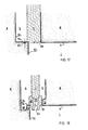
- Such sheets 68 can be used as shown in Figures 21 and 22.
- sheet 68 is placed on upper surface 34 of skin-strainer 2 in order that the combination of skin-strainer and its associated retaining means (the retaining means not being shown for the sake of simplicity) support the sheet 68.
- the sheet 68 covers the skin-strainer and extends beyond the sides of conduit 5, remaining partly pressed against the material of mold 8.
- Skin-strainer 2 is shown with one aperture 6, but it may be provided with a plurality of apertures.
- Aperture 6 is shown with a reversed taper when compared with the taper of aperture 6 in, for example, Figure 1, assuming that the mold casting cavity surface 3 is conventionally modified following the skin-strainer 2 central profile.
- sheet 68 restrains the open area of skin-strainer 2, thereby easing the choking of sprue-feeder 5, allowing filling of the cavity because of the metal permeability of the sheet 68, and feeding, when necessary, the corresponding casting because the thinness of the sheet 68 allows for the material of the sheet 68 to rapidly reach the temperature of the molten metal. Accordingly, the material of the sheet 68 does not promote early solidification and therefore does not block feeding toward the casting cavity.
- Such additional restraining means may naturally be called a restraining sheet 68.
- Figure 22 is identical to Figure 21 with the exception that the restraining sheet 68 rests freely on surface 34 of skin-strainer 2 and within the limit of the contour of conduit 5.
- the restraining sheet 68 can be more or less flexible, it can be advantageous in some cases to consider the simultaneous use of more than one layer, for example two superposed layers, placing a less flexible sheet directly on the skin-trainer and another more flexible sheet having better restraining quality on the top of it.
- restraining means reinforcing the effect of straining means such as skin-strainers, collars or the like, can be embodied by using materials permeable to molten metal, wether they are porous ceramics, thin flexible foraminous sheets of refractory materials, or the like.
- a feeding requirement will be present together with choking and filling though, sometimes, it might not be mandatory. For example, and as is well known in foundry practice, it could be so because the thinness of the casting promotes a rapid solidification, because the feeding is assured from another part of the casting through a traditional riser, because the feeding requirement is eliminated by the presence of chilling procedures, and the like.
- Figure 20 which and as already explained in this specification is used with a strainer having at least two apertures, corresponds to a system presenting two different open areas: one for choking and filling and the other for feeding. It could also correspond to a system presenting three different open areas by associating a cover to the strainer open area not blocked by blind restraining floating means: one area for choking (which eventually can be zero), a bigger one for filling and the biggest for feeding.
- the open area required for feeding is greater or even in some cases much greater than the area that is required for filling and, in turn, that the open area required for filling is greater or even much greater than the area required for choking.
- the present gating system being very compact, on one side, nevertheless still allows quite easily and efficiently, by the other, to adapt to any required diversity of consecutive open areas.
Landscapes
- Engineering & Computer Science (AREA)
- Mechanical Engineering (AREA)
- Molds, Cores, And Manufacturing Methods Thereof (AREA)
- Mold Materials And Core Materials (AREA)
- Casting Devices For Molds (AREA)
Claims (37)
- Moule de fonderie à coulée par gravité ayant un système d'alimentation et au moins une cavité pour la coulée entière du moule, dans lequel :- ledit système d'alimentation établissant nécessairement les chemins d'écoulement entre une ouverture vers l'extérieur du moule et ladite cavité 1 et comprenant au moins un conduit (5) formant un desdits chemins d'écoulement, ledit conduit étant ouvert à ses extrémités opposées et s'étendant directement d'une surface extérieure dudit moule à une surface de ladite cavité, ledit conduit comprenant des moyens pour recevoir le métal fondu et guider ledit métal fondu directement vers ladite cavité de telle sorte que, pendant la coulée, tout le métal passant par ledit conduit s'écoule directement vers ladite cavité, et- ledit système d'alimentation comprenant, en outre, des moyens de filtre interposés entre ledit conduit et ladite cavité,
caractérisé en ce que :- ladite cavité de coulée est distincte dudit système d'alimentation, correspond à une coulée intégrale qui doit être produite par ledit moule et est disposée à l'intérieur et forme une partie dudit moule ;- lesdits moyens de filtre (2) sont prévus avec des systèmes d'ouverture (12) formant une surface transversale totale de passage desdits moyens de filtre et s'étendant à travers lesdits moyens à partir dudit conduit vers ladite cavité etdes moyens de retenue (11,18,19,28,40,67,68) sont prévus qui sont distincts dudit moule et desdits moyens de filtre, pour bloquer, au moins partiellement, l'écoulement du métal fondu à travers lesdits systèmes d'ouverture pendant la coulée, lesdits moyens de retenue comprenant ainsi des moyens,, facilitant en premier lieu l'engorgement dudit conduit (5) pendant la coulée et assurant également la condition adéquate pour, en second lieu, remplir la cavité et troisièmement, et si nécessaire, pour alimenter également la coulée formée dans ladite cavité, à travers lesdits systèmes d'ouverture et après que ladite cavité a été remplie. - Dispositif selon la revendication 1, caractérisé en ce que ledit conduit comprend une descente de coulée (5), ledit moule comprend un dispositif d'allongement de descente de coulée (46, 47), ledit conduit passant à travers ledit dispositif d'allongement de descente de coulée et ayant à l'intérieur sensiblement la même surface transversale que celle dudit conduit (5) au niveau dudit filtre de peau (2).
- Dispositif selon la revendication 2, caractérisé en ce que ledit moule comprend de plus un dispositif d'élargissement de descente de coulée, ledit conduit (5) passant à travers ledit dispositif d'élargissement de descente de coulée et ayant à l'intérieur une surface transversale sensiblement plus grande que la section transversale dudit conduit au niveau du filtre de peau (2).
- Dispositif selon la revendication 1, caractérisé en ce que ledit conduit comprend une descente de coulée (5), ledit moule comprend en outre un dispositif d'élargissement de descente de coulée (46), ledit conduit passant à travers ledit dispositif d'élargissement de descente de coulée et ayant à l'intérieur une surface transversale plus grande que la section transversale dudit conduit au niveau dudit filtre de peau.
- Dispositif selon la revendication 1, caractérisé en ce que lesdits moyens de retenue comprennent au moins une pièce flottante de retenue (28) de composition et de forme telle qu'elle flottera quand ladite cavité (1) est pleine, ladite pièce flottante de retenue étant disposée dans une ouverture (6) dudit filtre de peau et obturant partiellement mais pas complètement ladite ouverture, formant de ce fait une surface de passage transversale réduite (29) présentée par l'assemblage de ladite pièce flottante de retenue et dudit filtre de peau (2), ladite pièce flottante de retenue étant supportée de sorte qu'elle est libre de flotter quand ladite cavité est pleine, augmentant de ce fait la surface transversale effective qui est disponible pour alimenter la coulée à travers l'ouverture dans laquelle ladite pièce flottante de retenue a été disposée, ladite pièce flottante de retenue étant capable de résister aux effets de température, de choc, de pression et d'érosion résultant de la coulée du métal fondu.
- Dispositif selon la revendication 5, caractérisé en ce que lesdits moyens de retenue comprennent de plus des moyens de couvercle (11) disposés dans ledit conduit pour obturer temporairement et davantage au moins une partie de ladite surface transversale réduite de passage (29) présentée par l'assemblage dudit filtre de peau (2) et de ladite pièce flottante de retenue (28).
- Dispositif selon la revendication 6, caractérisé en ce que les moyens de couvercle (11) sont disposés en contact avec ledit filtre de peau (2) et obturent une pluralité de ses ouvertures (12).
- Dispositif selon la revendication 6, caractérisé en ce que lesdits moyens de couvercle (11) sont disposés en contact avec ladite pièce flottante de retenue (28).
- Dispositif selon la revendication 8, caractérisé en ce que ladite pièce flottante de retenue possède un passage (29) formé à l'intérieur faisant communiquer ledit conduit (5) et ladite cavité (1) et formant au moins une partie de ladite surface transversale réduite de passage dudit assemblage du filtre de peau et de ladite pièce flottante de retenue, lesdits moyens de couvercle (11) comprenant des moyens pour fermer au moins partiellement ledit passage dans ladite pièce flottante de retenue.
- Dispositif selon la revendication 9, caractérisé en ce que lesdits systèmes d'ouverture du filtre de peau (2) comprennent une seule ouverture, lesdits moyens de couvercle étant reçus dans ledit passage de ladite pièce flottante de retenue.
- Dispositif selon la revendication 10 caractérisé en ce que lesdits moyens de couvercle (11) sont reçus dans dans ledit passage de ladite pièce flottante de retenue de telle sorte que au moins un canal soit formé entre eux faisant communiquer ledit conduit et ladite cavité.
- Dispositif selon la revendication 1, caractérisé en ce que lesdits moyens de retenue comprennent au moins une pièce non flottante (28) possédant une composition et une forme telle qu'elle ne flottera pas quand la cavité est pleine, ladite pièce non flottante étant disposée dans une ouverture dudit filtre de peau et obturant partiellement mais non complètement ladite ouverture, formant de ce fait une surface transversale réduite de passage présentée par l'assemblage de ladite pièce non flottante et dudit filtre de peau, ladite pièce non flottante comprenant un évidement (35) disposé de sorte qu'il se remplira de métal fondu, ledit évidement comprenant des moyens pour établir une source de chaleur de métal chaud adjacente thermiquement au métal de ladite surface transversale réduite de passage (29) dudit assemblage pour augmenter la capacité d'alimentation de ladite surface transversale réduite de passage.
- Dispositif selon la revendication 12, caractérisé en ce que les moyens de retenue comprennent de plus des moyens de couvercle (11) disposés dans ledit conduit pour obturer temporairement et davantage au moins une partie de ladite section transversale réduite de passage présentée par l'assemblage dudit filtre de peau et de ladite pièce non-flottante.
- Dispositif selon la revendication 13, caractérisé en ce que lesdits moyens de couvercle sont disposés en contact avec ledit filtre de peau (2) et obturent une pluralité de ses ouvertures (12).
- Dispositif selon la revendication 13, caractérisé en ce que lesdits moyens de couvercle sont disposés en contact avec ladite pièce non flottante.
- Dispositif selon la revendication 15, caractérisé en ce que ladite pièce non flottante possède un passage forme à l'intérieur faisant communiquer ledit conduit (5) et ladite cavité (1) et formant au moins une partie de ladite surface transversale réduite de passage dudit assemblage, lesdits moyens de couvercle (11) comprenant des moyens pour obturer au moins partiellement ledit passage dans ladite pièce non flottante.
- Dispositif selon la revendication 16, caractérisé en ce que lesdits systèmes d'ouverture du filtre de peau (2) comprennent une seule ouverture, lesdits moyens de couvercle étant reçus dans ledit passage de ladite pièce non flottante.
- Dispositif selon la revendication 17, caractérisé en ce que lesdits moyens de couvercle sont reçus dans ledit passage de ladite pièce non flottante de telle sorte qu'au moins un canal soit formé entre eux faisant communiquer ledit conduit et ladite cavité.
- Dispositif selon la revendication 1, caractérisé en ce que lesdits moyens de retenue comprennent lesdits moyens de couvercle (11) disposés en contact avec ledit filtre de peau (2) pour obturer temporairement au moins une partie de ladite surface transversale totale de passage dudit filtre de peau.
- Dispositif selon la revendication 19, caractérisé en ce que lesdits moyens de couvercle (11) comprennent au moins une surface de repère coopérant avec une paroi latérale (32) desdits systèmes d'ouverture (12) dudit filtre de peau pour garder lesdits moyens de couvercle en place pendant le remplissage.
- Dispositif selon la revendication 20, caractérisé en ce que lesdits moyens de couvercle comprennent de plus :- un corps standard et préfabriqué (18) réalisé en matériau réfractaire, au moins une dite surface de repère étant formée dessus, il existe un évidement sur le côté de dessous dudit corps et un trou s'étendant selon la longueur dudit corps et faisant communiquer avec ledit évidement ;- une barra métallique auxiliaire standard comme préfabriquée (22) comportant une tête à une de ses extrémités et un raccord à son autre extrémité, ladite barre étant disposée dans ledit trou de telle sorte que ladite tête est disposée dans ledit évidement ;- des moyens de serrage standard et préfabriqués (13) fixant ladite barre audit corps, dans lesquels ladite barre comprend des moyens de levage ; et- un mélange auxilaire réfractaire (27) remplissant l'espace restant dans ledit évidement recouvrant si nécessaire ladite tête de ladite barre et ajusté au contour externe dudit corps.
- Dispositif selon la revendication 21, caractérisé en ce que lesdits moyens de couvercle comprennent en outre, au moins une extension de couvercle auxiliaire standard et préfabriquée (19) réalisée en un matériau réfractaire et comportant un trou s'étendant le long de sa longueur, ladite barre métallique s'étendant à travers ledit trou de l'extension.
- Dispositif selon la revendication 20, caractérisé en ce que lesdits systèmes d'ouverture de filtre de peau comprennent une seule ouverture (12), ladite surface de repère desdits moyens de couvercle y étant disposée à l'intérieur.
- Dispositif selon la revendication 23, caractérisé en ce que la surface repère (15) s'adaptant à une paroi de ladite ouverture de telle sorte qu'au moins un canal soit formé entre elles faisant communiquer ledit conduit et ladite cavité.
- Dispositif selon les revendications 5, 12 ou 19, caractérisé en ce que lesdits moyens de retenue comprennent au moins une pièce flottante aveugle (67) de composition et de forme telle qu'elle flottera quand ladite cavité est pleine et des moyens supportant ladite pièce flottante aveugle de telle sorte qu'elle ne se déplacera pas sensiblement lors de la coulée initiale de métal fondu dans ledit conduit mais est libre de flotter quand ladite cavité est pleine, permettant de ce fait l'alimentation de la coulée à travers l'ouverture qui a été obturée par ladite pièce flottante aveugle, ladite pièce flottante aveugle étant capable de résister aux effets de température, de choc, de pression et d'érosion résultant de la coulée de métal fondu.
- Dispositif selon la revendication 1, caractérisé en ce qu'il comprend un produit de traitement métallurgique disposé dans ledit conduit (5), ledit produit comprenant des moyens pour traiter le métal fondu dans ledit conduit.
- Moule de fonderie à coulée par gravité selon les revendications 1-26, caractérisé en ce que ledit système d'alimentation comprend un collier (52) formé intégralement du matériau dudit moule et interposé entre ledit conduit et ladite cavité, une ouverture existant pour faire communiquer ledit conduit et ladite cavité à la position dudit collier.
- Dispositif selon la revendication 27, caractérisé en ce qu'il comprend une pièce d'insertion en bordure de collier distincte dudit moule et desdits moyens de retenue, ledit collier (52) supportant la pièce d'insertion en bordure de collier, ladite ouverture passant à travers ladite pièce d'insertion en bordure de collier.
- Dispositif selon la revendication 27, caractérisé en ce que le conduit comprend une descente de coulée, ledit moule comprenant un dispositif d'extension de descente de coulée, ledit conduit passant à travers ledit dispositif d'extension de descente de coulée (46) et y possédant à l'intérieur sensiblement la même surface transversale que la surface transversale dudit conduit au niveau du collier.
- Dispositif selon la revendication 29, caractérisé en ce que ledit moule comprend de plus un dispositif d'élargissement de descente de coulée (47), ledit conduit passant à travers ledit dispositif d'élargissement de descente de coulée et y comportant à l'intérieur une surface transversale sensiblement plus grande que la surface transversale dudit conduit au niveau dudit collier.
- Dispositif selon la revendication 27, caractérisé en ce que ledit conduit comprend une descente de coulée, ledit moule comprend en outre un dispositif d'élargissement de descente de coulée et y comportant à l'intérieur une surface transversale sensiblement plus grande que la surface transversale dudit conduit au niveau dudit collier.
- Dispositif selon la revendication 27, caractérisé en ce qu'il comprend un produit de traitement métallurgique disposé dans ledit conduit, ledit produit comrenant des moyens pour traiter le métal fondu dans ledit conduit.
- Moule de fonderie à coulée par gravité selon les revendications 1-32, caractérisé en ce qu'un des moyens de retenue est interposé le long de la longueur dudit conduit.
- Dispositif selon l'une quelconque des revendications 1 ou 27, caractérisé en ce que lesdits moyens de retenue comprennent une plaque mince foraminée (68) réalisée en matériau réfractaire.
- Dispositif selon l'une quelconque des revendications 1 ou 27, caractérisé en ce que lesdits moyens de retenue comprennent un matériau réfractaire foraminé.
- Dispositif selon l'une quelconque des revendications 1 ou 27, caractérisé en ce que lesdits moyens de retenue sont réalisés en un matériau capable de résister aux effets de température, de choc, de pression et d'érosion résultant de la coulée du métal fondu.
- Dispositif selon l'une quelconque des revendications 1 ou 27, caractérisé en ce que lesdits moyens de retenue comprennent des éléments standardisés préfabriqués.
Priority Applications (3)
| Application Number | Priority Date | Filing Date | Title |
|---|---|---|---|
| EP19880401113 EP0340367B1 (fr) | 1988-05-06 | 1988-05-06 | Système d'alimentation du moule dans une fonderie |
| DE19883872873 DE3872873T2 (de) | 1988-05-06 | 1988-05-06 | Giesserei-anschnitt-system. |
| ES88401113T ES2034299T3 (es) | 1988-05-06 | 1988-05-06 | Sistema de llenado de molde de fundicion. |
Applications Claiming Priority (1)
| Application Number | Priority Date | Filing Date | Title |
|---|---|---|---|
| EP19880401113 EP0340367B1 (fr) | 1988-05-06 | 1988-05-06 | Système d'alimentation du moule dans une fonderie |
Publications (2)
| Publication Number | Publication Date |
|---|---|
| EP0340367A1 EP0340367A1 (fr) | 1989-11-08 |
| EP0340367B1 true EP0340367B1 (fr) | 1992-07-15 |
Family
ID=8200386
Family Applications (1)
| Application Number | Title | Priority Date | Filing Date |
|---|---|---|---|
| EP19880401113 Expired EP0340367B1 (fr) | 1988-05-06 | 1988-05-06 | Système d'alimentation du moule dans une fonderie |
Country Status (3)
| Country | Link |
|---|---|
| EP (1) | EP0340367B1 (fr) |
| DE (1) | DE3872873T2 (fr) |
| ES (1) | ES2034299T3 (fr) |
Families Citing this family (4)
| Publication number | Priority date | Publication date | Assignee | Title |
|---|---|---|---|---|
| CN112719221B (zh) * | 2020-12-29 | 2025-02-18 | 太原科技大学 | 一种可变径浇口装置 |
| CN112935191B (zh) * | 2021-01-28 | 2023-03-03 | 共享装备股份有限公司 | 一种出气冒口 |
| CN113857434B (zh) * | 2021-10-26 | 2025-04-11 | 宜宾普什联动科技有限公司 | 金属阻隔片浇口盆装置 |
| CN116237493B (zh) * | 2023-02-27 | 2025-11-07 | 山西平阳重工机械有限责任公司 | 薄壁壳体的防变形制造方法 |
Family Cites Families (3)
| Publication number | Priority date | Publication date | Assignee | Title |
|---|---|---|---|---|
| US3831662A (en) * | 1972-12-22 | 1974-08-27 | Caterpillar Tractor Co | Casting mold with constricting device |
| US4154289A (en) * | 1976-04-06 | 1979-05-15 | Marie-Therese Simian | Gating system |
| GB2047139B (en) * | 1979-04-20 | 1983-05-18 | Jeanneret M | Mould gating system |
-
1988
- 1988-05-06 DE DE19883872873 patent/DE3872873T2/de not_active Expired - Fee Related
- 1988-05-06 ES ES88401113T patent/ES2034299T3/es not_active Expired - Lifetime
- 1988-05-06 EP EP19880401113 patent/EP0340367B1/fr not_active Expired
Also Published As
| Publication number | Publication date |
|---|---|
| DE3872873D1 (de) | 1992-08-20 |
| ES2034299T3 (es) | 1993-04-01 |
| DE3872873T2 (de) | 1993-03-04 |
| EP0340367A1 (fr) | 1989-11-08 |
Similar Documents
| Publication | Publication Date | Title |
|---|---|---|
| EP0327226B1 (fr) | Moules pour la coulée de métaux comportant des manchons pourvus d'un filtre | |
| US4154289A (en) | Gating system | |
| US6289969B1 (en) | Metal casting | |
| EP0738192B1 (fr) | Procede et materiel permettant d'alimenter des cavites de retrait dans les moulages en metal | |
| GB2183517A (en) | Casting using a lost pattern in the mould | |
| US4907640A (en) | Foundry gating system | |
| GB2200311A (en) | Molten metal discharging device | |
| CA1061985A (fr) | Machine de moulage pour anodes | |
| EP0340367A1 (fr) | Système d'alimentation du moule dans une fonderie | |
| US4749022A (en) | Foundry gating system | |
| AU594504B2 (en) | Feeder sleeves | |
| US6845810B2 (en) | Lost-foam casting apparatus for improved recycling of sprue-metal | |
| US6446698B1 (en) | Investment casting with exothermic material | |
| US3831662A (en) | Casting mold with constricting device | |
| US4802527A (en) | Apparatus for casting molten metal | |
| USRE31972E (en) | Casting mold with constricting device | |
| EP0246817A2 (fr) | Brique réfractaire creuse et procédé de coulée de métaux | |
| GB2047139A (en) | A mould gating system | |
| JP3386794B2 (ja) | 冶金用溶湯用の容器 | |
| CA1304560C (fr) | Tubes d'alimentation | |
| US6528010B2 (en) | Molten metal handling vessel | |
| JPH01293938A (ja) | 鋳造用ゲート装置 | |
| KR102294056B1 (ko) | 용기, 용기 처리 방법 및 용융물 처리 방법 | |
| CA1304559C (fr) | Moules pour moulage de metaux; tubes renfermant les filtres correspondants | |
| WO1979000795A1 (fr) | Membre formant ouverture pour modeles gazeifiables |
Legal Events
| Date | Code | Title | Description |
|---|---|---|---|
| PUAI | Public reference made under article 153(3) epc to a published international application that has entered the european phase |
Free format text: ORIGINAL CODE: 0009012 |
|
| AK | Designated contracting states |
Kind code of ref document: A1 Designated state(s): DE ES FR GB IT |
|
| 17P | Request for examination filed |
Effective date: 19900417 |
|
| 17Q | First examination report despatched |
Effective date: 19910117 |
|
| GRAA | (expected) grant |
Free format text: ORIGINAL CODE: 0009210 |
|
| AK | Designated contracting states |
Kind code of ref document: B1 Designated state(s): DE ES FR GB IT |
|
| PG25 | Lapsed in a contracting state [announced via postgrant information from national office to epo] |
Ref country code: IT Free format text: LAPSE BECAUSE OF FAILURE TO SUBMIT A TRANSLATION OF THE DESCRIPTION OR TO PAY THE FEE WITHIN THE PRE;WARNING: LAPSES OF ITALIAN PATENTS WITH EFFECTIVE DATE BEFORE 2007 MAY HAVE OCCURRED AT ANY TIME BEFORE 2007. THE CORRECT EFFECTIVE DATE MAY BE DIFFERENT FROM THE ONE RECORDED.SCRIBED TIME-LIMIT Effective date: 19920715 |
|
| REF | Corresponds to: |
Ref document number: 3872873 Country of ref document: DE Date of ref document: 19920820 |
|
| ET | Fr: translation filed | ||
| REG | Reference to a national code |
Ref country code: ES Ref legal event code: FG2A Ref document number: 2034299 Country of ref document: ES Kind code of ref document: T3 |
|
| PLBE | No opposition filed within time limit |
Free format text: ORIGINAL CODE: 0009261 |
|
| STAA | Information on the status of an ep patent application or granted ep patent |
Free format text: STATUS: NO OPPOSITION FILED WITHIN TIME LIMIT |
|
| 26N | No opposition filed | ||
| PGFP | Annual fee paid to national office [announced via postgrant information from national office to epo] |
Ref country code: GB Payment date: 19970428 Year of fee payment: 10 |
|
| PGFP | Annual fee paid to national office [announced via postgrant information from national office to epo] |
Ref country code: DE Payment date: 19970509 Year of fee payment: 10 |
|
| PGFP | Annual fee paid to national office [announced via postgrant information from national office to epo] |
Ref country code: FR Payment date: 19970513 Year of fee payment: 10 |
|
| PGFP | Annual fee paid to national office [announced via postgrant information from national office to epo] |
Ref country code: ES Payment date: 19970528 Year of fee payment: 10 |
|
| PG25 | Lapsed in a contracting state [announced via postgrant information from national office to epo] |
Ref country code: GB Free format text: LAPSE BECAUSE OF NON-PAYMENT OF DUE FEES Effective date: 19980506 |
|
| PG25 | Lapsed in a contracting state [announced via postgrant information from national office to epo] |
Ref country code: ES Free format text: LAPSE BECAUSE OF NON-PAYMENT OF DUE FEES Effective date: 19980507 |
|
| PG25 | Lapsed in a contracting state [announced via postgrant information from national office to epo] |
Ref country code: FR Free format text: LAPSE BECAUSE OF NON-PAYMENT OF DUE FEES Effective date: 19980531 |
|
| GBPC | Gb: european patent ceased through non-payment of renewal fee |
Effective date: 19980506 |
|
| PG25 | Lapsed in a contracting state [announced via postgrant information from national office to epo] |
Ref country code: DE Free format text: LAPSE BECAUSE OF NON-PAYMENT OF DUE FEES Effective date: 19990302 |
|
| REG | Reference to a national code |
Ref country code: FR Ref legal event code: ST |
|
| REG | Reference to a national code |
Ref country code: ES Ref legal event code: FD2A Effective date: 20000503 |