EP0340385B1 - Aufblasbare Dichtung - Google Patents
Aufblasbare Dichtung Download PDFInfo
- Publication number
- EP0340385B1 EP0340385B1 EP89100857A EP89100857A EP0340385B1 EP 0340385 B1 EP0340385 B1 EP 0340385B1 EP 89100857 A EP89100857 A EP 89100857A EP 89100857 A EP89100857 A EP 89100857A EP 0340385 B1 EP0340385 B1 EP 0340385B1
- Authority
- EP
- European Patent Office
- Prior art keywords
- sealing element
- slot
- region
- sealing
- mouth
- Prior art date
- Legal status (The legal status is an assumption and is not a legal conclusion. Google has not performed a legal analysis and makes no representation as to the accuracy of the status listed.)
- Expired - Lifetime
Links
- 238000007789 sealing Methods 0.000 title claims abstract description 63
- 239000011796 hollow space material Substances 0.000 claims 1
- 230000000694 effects Effects 0.000 description 4
- 230000009969 flowable effect Effects 0.000 description 4
- 230000000295 complement effect Effects 0.000 description 2
- 238000010168 coupling process Methods 0.000 description 2
- 230000001154 acute effect Effects 0.000 description 1
- 238000009792 diffusion process Methods 0.000 description 1
- 230000005489 elastic deformation Effects 0.000 description 1
- 239000013013 elastic material Substances 0.000 description 1
- 238000004519 manufacturing process Methods 0.000 description 1
- 238000003825 pressing Methods 0.000 description 1
- 238000009420 retrofitting Methods 0.000 description 1
- 230000003068 static effect Effects 0.000 description 1
Images
Classifications
-
- F—MECHANICAL ENGINEERING; LIGHTING; HEATING; WEAPONS; BLASTING
- F16—ENGINEERING ELEMENTS AND UNITS; GENERAL MEASURES FOR PRODUCING AND MAINTAINING EFFECTIVE FUNCTIONING OF MACHINES OR INSTALLATIONS; THERMAL INSULATION IN GENERAL
- F16J—PISTONS; CYLINDERS; SEALINGS
- F16J15/00—Sealings
- F16J15/46—Sealings with packing ring expanded or pressed into place by fluid pressure, e.g. inflatable packings
-
- F—MECHANICAL ENGINEERING; LIGHTING; HEATING; WEAPONS; BLASTING
- F16—ENGINEERING ELEMENTS AND UNITS; GENERAL MEASURES FOR PRODUCING AND MAINTAINING EFFECTIVE FUNCTIONING OF MACHINES OR INSTALLATIONS; THERMAL INSULATION IN GENERAL
- F16L—PIPES; JOINTS OR FITTINGS FOR PIPES; SUPPORTS FOR PIPES, CABLES OR PROTECTIVE TUBING; MEANS FOR THERMAL INSULATION IN GENERAL
- F16L17/00—Joints with packing adapted to sealing by fluid pressure
- F16L17/10—Joints with packing adapted to sealing by fluid pressure the packing being sealed by the pressure of a fluid other than the fluid in or surrounding the pipe
Definitions
- the invention relates to an inflatable seal according to the preamble of claim 1.
- Such a seal is known from FR-A-1 310 018. It has a balanced contact pressure of the sealing surface on the component to be sealed. However, the service life of corresponding seals is unsatisfactory.
- the invention has for its object to develop a seal of the type mentioned in such a way that there is a significantly improved service life with a balanced contact pressure of the sealing surface.
- the sealing element is provided with mutually facing, second strips arranged in the region of the bottom of the groove, which are at a distance from one another. In this way, a special permanent and excellent sealing of the cavity enclosed by the elastic sealing element and the groove is obtained.
- the sealing element can have a mirror-inverted profile.
- the sealing element should also have a wall thickness at the thinnest point in the area behind its sealing surface, which is about 3 - 5 times as large as the distance between the first strips. Furthermore, a plurality of sealing lips extending parallel to the sealing element can be provided in the area of the sealing surface, which increases the sealing effect. Two of these sealing lips should be as close as possible to the adjacent first strips in order to prevent the occurrence of a tilting moment in the sealing element during its pressurization.
- the sealing element is provided at least in the region of the bottom and in the region of the side surfaces of the groove with two sealing lips each extending parallel to its longitudinal direction. Production-related surface unevenness of the sealing element and / or the groove can thereby be bridged, whereby it is of crucial importance that the individual sealing lips complement each other in their effect through their series connection within the sealing gap.
- the support surfaces forming part of the lateral wall of the groove and the direction of movement of the sealing element that results when the cavity is pressurized can enclose an acute angle, expediently such an angle between 55 and 80 °.
- the expansion of the sealing element that results when the cavity is pressurized is in one such cases not only limited to the cross-sectional area behind its sealing surface, but in a uniform manner to almost the entirety of the profile, which is essentially of the same wall thickness at all points.
- the specific cross-sectional load is accordingly significantly reduced.
- the sealing surface can be pressed against the opposite component with an arbitrarily high force depending on the pressure of the flowable medium fed into the cavity.
- the sealing effect achieved in relation to the same can thereby be controlled in a sensitive manner.
- the seal is particularly suitable for use in sealing between butt-jointed ends of pipes. However, it can also be used for sealing shafts or in the area of straight gaps.
- the groove 3 is narrowed in the region of its mouth on the inside and outside in a mirror-image manner by the first strips 8, which engage behind the sealing element 4 on both sides of the sealing surface 7 with wedge-shaped inclined support surfaces 9.
- the support surfaces 9 enclose an angle of 60 ° with the direction of movement that results when the interior 5 is pressurized.
- the sealing element consists of rubber-elastic material with a hardness of 55 Shore A. It is provided with second strips 11, which are formed in one piece and are arranged in the region of the bottom 10 of the groove 3 and face one another and have a spacing B from one another. In the space formed by the distance B, the supply opening 6 opens, through which pressurized, flowable medium can be fed into the cavity 5 and removed therefrom.
- the sealing element in the area of the base 10 and in the area of the side surfaces 12 of the groove 3 each have two sealing lips 13 which extend parallel to its longitudinal direction and which provide a good seal of the sealing element with respect to the walls of the groove.
- the individual sealing lips are arranged in a series connection in the overall resulting sealing gap. They can therefore complement each other in their effect.
- the sealing element of the seal shown has the shape shown in the uninflated state.
- a prestressed, flowable medium is fed into the interior 5, an elastic deformation results, which results in the sealing surface 7 being pressed against the component 2 to be sealed. Almost all of its side and end wall components are included in the associated deformations of the sealing element.
- the sealing element of the seal according to the invention When not in use, the sealing element of the seal according to the invention is protected in an excellent manner by its sealing surface 7, rigid, protruding, first strips 8 of one component 1. Use under rough operating conditions is therefore possible without any problems.
Landscapes
- Engineering & Computer Science (AREA)
- General Engineering & Computer Science (AREA)
- Physics & Mathematics (AREA)
- Fluid Mechanics (AREA)
- Mechanical Engineering (AREA)
- Architecture (AREA)
- Sealing Devices (AREA)
- Materials For Medical Uses (AREA)
- Gasket Seals (AREA)
- Specific Sealing Or Ventilating Devices For Doors And Windows (AREA)
Description
- Die Erfindung betrifft eine aufblasbare Dichtung nach dem Oberbegriff von Anspruch 1.
- Eine solche Dichtung ist aus der FR-A-1 310 018 bekannt. Sie weist eine ausgeglichene Anpressung der Dichtfläche an das abzudichtende Bauteil auf. Die Gebrauchsdauer entsprechender Dichtungen ist jedoch wenig befriedigend.
- Der Erfindung liegt die Aufgabe zugrunde, eine Dichtung der eingangs genannten Art derart weiter zu entwickeln, daß sich bei ausgeglichener Anpressung der Dichtfläche eine deutlich verbesserte Gebrauchsdauer ergibt.
- Diese Aufgabe wird erfindungsgemäß bei einer Dichtung der eingangs genannten Art mit den kennzeichnenden Merkmalen von Anspruch 1 gelöst. Auf vorteilhafte Ausgestaltungen nehmen die Unteransprüche bezug.
- Bei der erfindungsgemäßen Dichtung ist das Dichtelement mit im Bereich des Bodens der Nut angeordneten, einander zugewandten, zweiten Leisten versehen, die einen Abstand voneinander haben. Hierdurch wird eine besondere dauerhafte und ausgezeichnete Abdichtung des von dem elastischen Dichtelement und der Nut umschlossenen Hohlraums erhalten.
- Das Dichtelement kann ein spiegelbildlich gestaltetes Profil aufweisen.
- Die Gefahr eines Verlustes des Dichtelements bei einer Druckbeaufschlagung des Innenraumes in Fällen, in denen das abzudichtende Bauteil nicht verfügbar ist, wird dadurch reduziert. Um dennoch eine ausreichende Elastizität und Dauerhaltbarkeit zu erreichen, sollte das Dichtelement darüber hinaus im Bereich rückwärtig seiner Dichtfläche an der dünnsten Stelle eine Wandstärke haben, die etwa 3 - 5 mal so groß ist wie der gegenseitige Abstand der ersten Leisten. Desweiteren können im Bereich der Dichtfläche mehrere, sich parallel zu dem Dichtelement erstreckende Dichtlippen vorgesehen sein, was die Abdichtwirkung erhöht. Zwei dieser Dichtlippen sollten dabei den beiderseits benachbarten ersten Leisten möglichst dicht benachbart sein um das Auftreten eines Kippmoments in dem Dichtelement während seiner Druckbeaufschlagung zu verhindern.
- Nach einer anderen Ausgestaltung ist es vorgesehen, daß das Dichtelement wenigstens im Bereich des Bodens und im Bereich der Seitenflächen der Nut mit jeweils zwei sich parallel zu seiner Längsrichtung erstreckenden Dichtlippen versehen ist. Herstellungsbedingte Oberflächenunebenheiten des Dichtelementes und/oder der Nut lassen sich hierdurch überbrücken, wobei es von entscheidender Bedeutung ist, daß die einzelnen Dichtlippen durch ihre Reihenschaltung innerhalb des Dichtspaltes einander in ihrer Wirkung ergänzen.
- In den Hohlraum der Dichtung wird regulär nur während der bestimmungsgemäßen Verwendung und nur in dem erforderlichen Maße vorgespanntes, fließfähiges Medium eingespeist. Hiedurch wird eine ausgeglichene Anpreßung der Dichtfläche an das abzudichtende Bauteil bewirkt, wodurch die diffusionsbedingten Verluste an vorgespanntem Medium nicht störend in Erscheinung treten. Sie werden in Abhängigkeit von den Erfordernissen jeweils ersetzt.
- Die einen Bestandteil der seitlichen Wandung der Nut bildenden Stützflächen und die sich bei einer Druckbeaufschlagung des Hohlraumes ergebende Bewegungsrichtung des Dichtelements können einen spitzen Winkel einschließen, zweckmäßig einen solchen zwischen 55 und 80°.Die sich bei Druckbeaufschlagung des Hohlraumes ergebende Dehnung des Dichtelementes ist in einem solchen Falle nicht nur auf den hinter dessen Dichtfläche liegenden Querschnittsbereich beschränkt, sondern in einer gleichmäßigen Weise auf nahezu die Gesamtheit des Profils, welches im wesentlichen an allen Stellen von übereinstimmender Wandstärke ist. Die spezifische Querschnittsbelastung ist dementsprechend deutlich reduziert.
- Bei der Dichtung läßt sich die Dichtfläche in Abhängigkeit von dem Druck des in den Hohlraum eingespeisten, fließfähigen Mediums mit einer beliebig hohen Kraft an das gegenüberliegende Bauteil anpressen. Die gegenüber demselben erzielte Abdichtwirkung läßt sich hierdurch auf feinfühlige Weise steuern.
- Die Dichtung eignet sich durch ihre spezielle Gestaltung insbesondere zur Verwendung bei der Abdichtung zwischen stumpf aufeinander stoßende Enden von Rohren. Eine Verwendung bei der Abdichtung von Wellen oder im Bereich von gradlinig verlaufenden Spalten ist jedoch ebenfalls möglich.
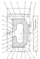
- Der Gegenstand der Erfindung wird nachfolgend anhand der in der Anlage beigefügten Zeichnung weiter verdeutlicht. Diese nimmt bezug auf die gegenseitige Abdichtung der Stirnflächen zweier stumpf aufeinander stoßender Rohre. In der einen ist die umlaufende Nut 3 vorgesehen, welche in Richtung der anderen Stirnfläche geöffnet ist.
- Die Nut 3 ist im Bereich ihrer Mündung innen- und außenseitig in spiegelbildlicher Weise verengt durch die ersten Leisten 8, welche das Dichtelement 4 beiderseits der Dichtfläche 7 mit keilförmig geneigten Stützflächen 9 hintergreifen. Die Stützflächen 9 schließen mit der sich bei einer Druckbeaufschlagung des Innenraumes 5 ergebenden Bewegungsrichtung einen Winkel von 60° ein.
- Das Dichtelement besteht aus gummielastischen Werkstoff einer Härte von 55 Shore A. Es ist mit einstückig angeformten, im Bereich des Bodens 10 der Nut 3 angeordnet, einander zugewandten, zweiten Leisten 11 versehen, die einen Abstand B voneinander haben. In den durch den Abstand B gebildeten Zwischenraum mündet die Versorgungsöffnung 6, durch welche druckbeaufschlagtes, fließfähiges Medium in den Hohlraum 5 einspeisbar und aus demselben entfernbar ist.
- Desweiteren weist das Dichtelement im Bereich des Bodens 10 und im Bereich der Seitenflächen 12 der Nut 3 jeweils zwei sich parallel zu seiner Längsrichtung erstreckende Dichtlippen 13 auf, die eine gute Abdichtung des Dichtelementes gegenüber den Wandungen der Nut bewirken. Die einzelnen Dichtlippen sind in dem sich insgesamt ergebenden Dichtspalt in einer Reihenschaltung angeordnet. Sie vermögen daher einander in ihrer Wirkung zu ergänzen.
- Das Dichtelement der gezeigten Dichtung hat im nicht aufgeblähten Zustand die dargestellte Form. Bei einer Einspeisung eines vorgespannten, fließfähigen Mediums in den Innenraum 5 ergibt sich eine elastische Deformierung, welche eine Anpreßung der Dichtfläche 7 an das abzudichtende Bauteil 2 zur Folge hat. In die zugehörigen Deformierungen des Dichtelementes sind nahezu dessen gesamte Seiten- und Stirnwandungsbestandteile mit einbezogen.
- Bei Anwendung der in der Zeichnung gezeigten Proportionen ist bei den üblichen Versorgungsdrücken in Druckluftnetzen, diese betragen etwa 6 bar (kp/cm²) eine Schädigung oder ein Verlust des Dichtelementes 4 bei einer Druckbeaufschlagung des Hohlraumes 5 auch dann nicht zu befürchten, wenn das abzudichtende Bauteil 2, beispielsweise in Ermangelung eines vorausgegangenen Kupplungsvorganges, nicht verfügbar ist. In diesem Falle ist nämlich die sich ergebende Haftreibung insbesondere im Bereich der Dichtlippen 13 derart groß, daß das Dichtelement 4 in zuverlässiger Weise festgehalten wird. Nach Entlastung des Innenraumes 5 und nachgeholtem Kupplungsvorgang läßt sich daher auch in einem solchen Falle die erfindungsgemäße Dichtung ohne weiteres entsprechend den Erfordernissen aktivieren.
- Das Dichtelement der erfindungsgemäßen Dichtung ist bei Nichtgebrauch in einer ausgezeichneten Weise durch seine Dichtfläche 7 in Bewegungsrichtung überragenden, unnachgiebigen, ersten Leisten 8 des einen Bauteils 1 geschützt. Eine Verwendung unter rauhen Betriebsbedingungen ist daher problemlos möglich.
Claims (3)
- Aufblasbare Dichtung für den Spalt zwischen zwei sich parallel zueinander erstreckenden, unnachgiebigen Bauteilen (1,2) umfassend eine U-förmig in Richtung des Spaltes geöffnete Nut (3), in einem der Bauteile (1,2), ein in der Nut (3) gelagertes, gummielastisches Dichtelement (4) von entgegengesetzt U-förmigem Profil sowie eine in den von der Nut (3) und dem Dichtelement (4) umschlossenen Hohlraum (5) mündende Versorgungsöffnung (6), wobei das Dichtelement (4) im Bereich der Mündung der Nut mit einer Dichtfläche (7) versehen ist, wobei das Dichtelement (4) beweglich in der Nut (3) gelagert ist, wobei die Nut (3) im Bereich der Mündung durch beiderseitige, einander zugewandte, erste Leisten (8) verengt ist, die das Dichtelement (4) im Bereich der Mündung mit Stützflächen (9) hintergreifen und wobei die ersten Leisten (8) im Bereich der Mündung einen Abstand voneinander haben, der drei bis fünf mal so groß ist wie die Dicke der dünnsten Stelle der Wandung des Dichtelementes im Bereich der Mündung, dadurch gekennzeichnet, daß das Dichtelement (4) mit im Bereich des Bodens (10) der Nut (3) angeordneten, einander zugewandten, zweiten Leisten (11) versehen ist, die einen Abstand (B) voneinander haben.
- Dichtung nach Anspruch 1, dadurch gekennzeichnet, daß das Dichtelement (4) ein spiegelbildlich gestaltetes Profil aufweist.
- Dichtung nach Anspruch 1 bis 2, dadurch gekennzeichnet, daß das Dichtelement (4) wenigstens im Bereich des Bodens (10) und der Seitenflächen (12) der Nut (3) mit jeweils zwei sich parallel zu seiner Längsrichtung erstreckenden Dichtlippen (13) versehen ist.
Priority Applications (1)
| Application Number | Priority Date | Filing Date | Title |
|---|---|---|---|
| AT89100857T ATE86720T1 (de) | 1988-05-06 | 1989-01-19 | Aufblasbare dichtung. |
Applications Claiming Priority (2)
| Application Number | Priority Date | Filing Date | Title |
|---|---|---|---|
| DE3815455A DE3815455C2 (de) | 1988-05-06 | 1988-05-06 | Aufblasbare Dichtung |
| DE3815455 | 1988-05-06 |
Publications (3)
| Publication Number | Publication Date |
|---|---|
| EP0340385A2 EP0340385A2 (de) | 1989-11-08 |
| EP0340385A3 EP0340385A3 (en) | 1990-08-29 |
| EP0340385B1 true EP0340385B1 (de) | 1993-03-10 |
Family
ID=6353778
Family Applications (1)
| Application Number | Title | Priority Date | Filing Date |
|---|---|---|---|
| EP89100857A Expired - Lifetime EP0340385B1 (de) | 1988-05-06 | 1989-01-19 | Aufblasbare Dichtung |
Country Status (3)
| Country | Link |
|---|---|
| EP (1) | EP0340385B1 (de) |
| AT (1) | ATE86720T1 (de) |
| DE (2) | DE3815455C2 (de) |
Cited By (6)
| Publication number | Priority date | Publication date | Assignee | Title |
|---|---|---|---|---|
| US8544304B2 (en) | 2007-08-24 | 2013-10-01 | Tenaris Connections Limited | Method for improving fatigue resistance of a threaded joint |
| US8840152B2 (en) | 2010-03-26 | 2014-09-23 | Tenaris Connections Limited | Thin-walled pipe joint |
| US9004544B2 (en) | 2009-04-22 | 2015-04-14 | Tenaris Connections Limited | Threaded joint for tubes, pipes and the like |
| US9234612B2 (en) | 2007-06-22 | 2016-01-12 | Tenaris Connections Limited | Threaded joint with energizable seal |
| US9383045B2 (en) | 2007-07-16 | 2016-07-05 | Tenaris Connections Limited | Threaded joint with resilient seal ring |
| KR20220042936A (ko) * | 2020-09-28 | 2022-04-05 | 한국항공우주연구원 | 인공위성용 컨테이너의 밀폐 시스템 및 이를 이용하는 인공위성용 컨테이너의 밀폐 방법 |
Families Citing this family (26)
| Publication number | Priority date | Publication date | Assignee | Title |
|---|---|---|---|---|
| EP0479172B1 (de) | 1990-09-28 | 1995-07-19 | Phoenix Aktiengesellschaft | Steckmuffenverbindung |
| DE4306323A1 (de) * | 1993-03-01 | 1994-09-08 | Schottel Werft | Schiffsantriebsanlage mit einem unter dem vorzugsweise im wesentlichen oder im Bereich der Antriebsanlage ebenen Schiffsboden angeordneten Antriebspropeller |
| NL9300699A (nl) * | 1993-04-23 | 1994-11-16 | Stork Hubert Cheese Systems | Afdichtingselement. |
| EP0708288B1 (de) * | 1994-10-19 | 1999-03-31 | Tetra Laval Holdings & Finance S.A. | Vorrichtung zum Abtrennen von Molke |
| US5660396A (en) * | 1994-10-26 | 1997-08-26 | Tebel--MKT B.V. | Whey draining apparatus having sealing element |
| DE19708579C2 (de) * | 1997-03-03 | 1999-06-17 | Fritsche Moellmann Gmbh Co Kg | Dichteinrichtung |
| DE10102103A1 (de) * | 2001-01-18 | 2002-09-12 | Sachtleben Chemie Gmbh | Dichtungsbalgsystem für rotierende Wellen |
| DE10135724B4 (de) * | 2001-07-26 | 2005-07-21 | Müller Weingarten AG | Abdichtung von Formen |
| DE102006028408A1 (de) | 2006-04-10 | 2007-10-31 | Franz Haimer Maschinenbau Kg | Auszugssicherung von Werkzeugen aus Werkzeughaltern mit einer Werkzeugaufnahme |
| GB2446598B (en) * | 2007-01-18 | 2009-04-29 | Motorola Inc | Device, housing element and sealing element therefor |
| DE202011109498U1 (de) | 2011-12-27 | 2012-02-13 | Franz Haimer Maschinenbau Kg | Werkzeughalter und Spannsystem mit einem derartigen Werkzeughalter |
| DE602007011046D1 (de) * | 2007-06-27 | 2011-01-20 | Tenaris Connections Ag | Gewindeverbindung mit unter Druck setzbarer Dichtung |
| DE602007013892D1 (de) | 2007-08-24 | 2011-05-26 | Tenaris Connections Ag | Gewindeverbindungsstück mit hoher Radiallast und unterschiedlich behandelten Oberflächen |
| EP2096253B1 (de) | 2008-02-29 | 2010-06-16 | Tenaris Connections AG | Gewindeverbindungsstück mit verbesserten elastischen Dichtungsringen |
| EP2325435B2 (de) | 2009-11-24 | 2020-09-30 | Tenaris Connections B.V. | Verschraubung für [ultrahoch] abgedichteten internen und externen Druck |
| US9163296B2 (en) | 2011-01-25 | 2015-10-20 | Tenaris Coiled Tubes, Llc | Coiled tube with varying mechanical properties for superior performance and methods to produce the same by a continuous heat treatment |
| DE202011102529U1 (de) | 2011-06-28 | 2011-11-07 | Kleihues Betonbauteile Gmbh & Co.Kg | Dichtring |
| US9970242B2 (en) | 2013-01-11 | 2018-05-15 | Tenaris Connections B.V. | Galling resistant drill pipe tool joint and corresponding drill pipe |
| US9803256B2 (en) | 2013-03-14 | 2017-10-31 | Tenaris Coiled Tubes, Llc | High performance material for coiled tubing applications and the method of producing the same |
| EP2789701A1 (de) | 2013-04-08 | 2014-10-15 | DALMINE S.p.A. | Hochfeste mittelwandige vergütete und nahtlose Stahlrohre und entsprechendes Verfahren zur Herstellung der Stahlrohre |
| EP2789700A1 (de) | 2013-04-08 | 2014-10-15 | DALMINE S.p.A. | Dickwandige vergütete und nahtlose Stahlrohre und entsprechendes Verfahren zur Herstellung der Stahlrohre |
| JP6144417B2 (ja) | 2013-06-25 | 2017-06-07 | テナリス・コネクシヨンズ・ベー・ブイ | 高クロム耐熱鋼 |
| US20160305192A1 (en) | 2015-04-14 | 2016-10-20 | Tenaris Connections Limited | Ultra-fine grained steels having corrosion-fatigue resistance |
| US11124852B2 (en) | 2016-08-12 | 2021-09-21 | Tenaris Coiled Tubes, Llc | Method and system for manufacturing coiled tubing |
| US10434554B2 (en) | 2017-01-17 | 2019-10-08 | Forum Us, Inc. | Method of manufacturing a coiled tubing string |
| DE102025105132A1 (de) | 2025-02-12 | 2026-03-12 | Zf Friedrichshafen Ag | Dichtungsanordnung |
Family Cites Families (9)
| Publication number | Priority date | Publication date | Assignee | Title |
|---|---|---|---|---|
| FR1310018A (de) * | 1963-03-04 | |||
| GB1115436A (en) * | 1965-01-18 | 1968-05-29 | Richard Laurence Olson | Improvements in or relating to pressure assembly seals |
| US3574360A (en) * | 1969-02-19 | 1971-04-13 | Caterpillar Tractor Co | Fluid-pressure-type hose clamp |
| DE2610730A1 (de) * | 1976-03-13 | 1977-09-22 | Daimler Benz Ag | Wellendichtring mit innendruckbeaufschlagung |
| SE413200B (sv) * | 1978-08-14 | 1980-04-28 | Asea Atom Ab | Tetningsanordning for tillfellig tryckavtetning |
| US4302018A (en) * | 1980-02-29 | 1981-11-24 | Foster-Miller Associates, Inc. | Packer arrangements for oil wells and the like |
| US4529211A (en) * | 1982-03-29 | 1985-07-16 | William Rodgers | Pipe joint and seal |
| DE3511524C1 (de) * | 1985-03-29 | 1986-06-05 | Howaldtswerke - Deutsche Werft AG Hamburg und Kiel, 2300 Kiel | Schottabdichtung |
| DE3600691A1 (de) * | 1986-01-13 | 1987-07-16 | Rheinhuette Vorm Ludwig Beck G | Dichtung zum abdichten eines dichtspaltes zwischen relativ zueinander beweglichen koerpern |
-
1988
- 1988-05-06 DE DE3815455A patent/DE3815455C2/de not_active Expired - Lifetime
-
1989
- 1989-01-19 DE DE8989100857T patent/DE58903692D1/de not_active Expired - Lifetime
- 1989-01-19 EP EP89100857A patent/EP0340385B1/de not_active Expired - Lifetime
- 1989-01-19 AT AT89100857T patent/ATE86720T1/de not_active IP Right Cessation
Cited By (6)
| Publication number | Priority date | Publication date | Assignee | Title |
|---|---|---|---|---|
| US9234612B2 (en) | 2007-06-22 | 2016-01-12 | Tenaris Connections Limited | Threaded joint with energizable seal |
| US9383045B2 (en) | 2007-07-16 | 2016-07-05 | Tenaris Connections Limited | Threaded joint with resilient seal ring |
| US8544304B2 (en) | 2007-08-24 | 2013-10-01 | Tenaris Connections Limited | Method for improving fatigue resistance of a threaded joint |
| US9004544B2 (en) | 2009-04-22 | 2015-04-14 | Tenaris Connections Limited | Threaded joint for tubes, pipes and the like |
| US8840152B2 (en) | 2010-03-26 | 2014-09-23 | Tenaris Connections Limited | Thin-walled pipe joint |
| KR20220042936A (ko) * | 2020-09-28 | 2022-04-05 | 한국항공우주연구원 | 인공위성용 컨테이너의 밀폐 시스템 및 이를 이용하는 인공위성용 컨테이너의 밀폐 방법 |
Also Published As
| Publication number | Publication date |
|---|---|
| DE3815455A1 (de) | 1989-11-23 |
| EP0340385A2 (de) | 1989-11-08 |
| EP0340385A3 (en) | 1990-08-29 |
| ATE86720T1 (de) | 1993-03-15 |
| DE3815455C2 (de) | 1994-10-20 |
| DE58903692D1 (de) | 1993-04-15 |
Similar Documents
| Publication | Publication Date | Title |
|---|---|---|
| EP0340385B1 (de) | Aufblasbare Dichtung | |
| DE69121244T2 (de) | Dichtungsvorrichtung | |
| CH660849A5 (de) | Filterplatte. | |
| EP1268968B1 (de) | Verbundprofil und verfahren zur herstellung eines verbundprofils | |
| DE3436158C2 (de) | ||
| DE3430062C2 (de) | ||
| DE3390418C2 (de) | Filterpresse | |
| DE4015166A1 (de) | Verglastes gebaeudeteil | |
| DE2655737A1 (de) | Hydraulische presse | |
| DE9306553U1 (de) | Schaltleiste | |
| EP0633358B1 (de) | Vorrichtung zum Überbrücken einer Dehnungsfuge in einer Fahrbahn, insbesondere von Brücken | |
| EP0066279B1 (de) | Fensterinnendichtung | |
| DE9116436U1 (de) | Konstruktion aus Profilstäben und Binderprofilen | |
| DE3140512A1 (de) | Verdraengermaschine | |
| DD269825A5 (de) | Extrusionskopf mit einer klemmeinrichtung fuer die werkzeugteile | |
| DE3324833C2 (de) | Haltevorrichtung für rechteckige Düsenplatten | |
| DE69004381T2 (de) | Profildichtung aus Elastomer für Tunnelgewölbe. | |
| DE9106181U1 (de) | Dichtungsprofil | |
| EP0352403A2 (de) | Ringdichtung | |
| DE3238489A1 (de) | Pleuelstange | |
| EP0321719B1 (de) | Koksofentür | |
| EP2082836A1 (de) | Positioniervorrichtung für Werkstücke | |
| DE69816186T2 (de) | Mechanische Kette | |
| AT2690U1 (de) | Kolbenstangenloser druckmittelzylinder | |
| EP0786280A2 (de) | Membranfilterplatte für eine Filterpresse |
Legal Events
| Date | Code | Title | Description |
|---|---|---|---|
| PUAI | Public reference made under article 153(3) epc to a published international application that has entered the european phase |
Free format text: ORIGINAL CODE: 0009012 |
|
| AK | Designated contracting states |
Kind code of ref document: A2 Designated state(s): AT BE CH DE FR GB IT LI NL SE |
|
| PUAL | Search report despatched |
Free format text: ORIGINAL CODE: 0009013 |
|
| AK | Designated contracting states |
Kind code of ref document: A3 Designated state(s): AT BE CH DE FR GB IT LI NL SE |
|
| 17P | Request for examination filed |
Effective date: 19900903 |
|
| 17Q | First examination report despatched |
Effective date: 19920220 |
|
| ITF | It: translation for a ep patent filed | ||
| GRAA | (expected) grant |
Free format text: ORIGINAL CODE: 0009210 |
|
| AK | Designated contracting states |
Kind code of ref document: B1 Designated state(s): AT BE CH DE FR GB IT LI NL SE |
|
| REF | Corresponds to: |
Ref document number: 86720 Country of ref document: AT Date of ref document: 19930315 Kind code of ref document: T |
|
| ET | Fr: translation filed | ||
| REF | Corresponds to: |
Ref document number: 58903692 Country of ref document: DE Date of ref document: 19930415 |
|
| GBT | Gb: translation of ep patent filed (gb section 77(6)(a)/1977) |
Effective date: 19930331 |
|
| PLBE | No opposition filed within time limit |
Free format text: ORIGINAL CODE: 0009261 |
|
| STAA | Information on the status of an ep patent application or granted ep patent |
Free format text: STATUS: NO OPPOSITION FILED WITHIN TIME LIMIT |
|
| ITTA | It: last paid annual fee | ||
| 26N | No opposition filed | ||
| EAL | Se: european patent in force in sweden |
Ref document number: 89100857.5 |
|
| PGFP | Annual fee paid to national office [announced via postgrant information from national office to epo] |
Ref country code: SE Payment date: 19961216 Year of fee payment: 9 |
|
| PGFP | Annual fee paid to national office [announced via postgrant information from national office to epo] |
Ref country code: GB Payment date: 19970107 Year of fee payment: 9 |
|
| PGFP | Annual fee paid to national office [announced via postgrant information from national office to epo] |
Ref country code: FR Payment date: 19970108 Year of fee payment: 9 |
|
| PGFP | Annual fee paid to national office [announced via postgrant information from national office to epo] |
Ref country code: AT Payment date: 19970109 Year of fee payment: 9 |
|
| PGFP | Annual fee paid to national office [announced via postgrant information from national office to epo] |
Ref country code: DE Payment date: 19970110 Year of fee payment: 9 |
|
| PGFP | Annual fee paid to national office [announced via postgrant information from national office to epo] |
Ref country code: NL Payment date: 19970131 Year of fee payment: 9 |
|
| PGFP | Annual fee paid to national office [announced via postgrant information from national office to epo] |
Ref country code: BE Payment date: 19970211 Year of fee payment: 9 |
|
| PGFP | Annual fee paid to national office [announced via postgrant information from national office to epo] |
Ref country code: CH Payment date: 19970414 Year of fee payment: 9 |
|
| PG25 | Lapsed in a contracting state [announced via postgrant information from national office to epo] |
Ref country code: DE Effective date: 19970718 |
|
| PG25 | Lapsed in a contracting state [announced via postgrant information from national office to epo] |
Ref country code: GB Free format text: LAPSE BECAUSE OF NON-PAYMENT OF DUE FEES Effective date: 19980119 Ref country code: AT Free format text: LAPSE BECAUSE OF NON-PAYMENT OF DUE FEES Effective date: 19980119 |
|
| PG25 | Lapsed in a contracting state [announced via postgrant information from national office to epo] |
Ref country code: SE Free format text: LAPSE BECAUSE OF NON-PAYMENT OF DUE FEES Effective date: 19980120 |
|
| PG25 | Lapsed in a contracting state [announced via postgrant information from national office to epo] |
Ref country code: LI Free format text: LAPSE BECAUSE OF NON-PAYMENT OF DUE FEES Effective date: 19980131 Ref country code: FR Free format text: THE PATENT HAS BEEN ANNULLED BY A DECISION OF A NATIONAL AUTHORITY Effective date: 19980131 Ref country code: CH Free format text: LAPSE BECAUSE OF NON-PAYMENT OF DUE FEES Effective date: 19980131 Ref country code: BE Free format text: LAPSE BECAUSE OF NON-PAYMENT OF DUE FEES Effective date: 19980131 |
|
| BERE | Be: lapsed |
Owner name: FIRMA CARL FREUDENBERG Effective date: 19980131 |
|
| PG25 | Lapsed in a contracting state [announced via postgrant information from national office to epo] |
Ref country code: NL Free format text: LAPSE BECAUSE OF NON-PAYMENT OF DUE FEES Effective date: 19980801 |
|
| GBPC | Gb: european patent ceased through non-payment of renewal fee |
Effective date: 19980119 |
|
| REG | Reference to a national code |
Ref country code: CH Ref legal event code: PL |
|
| NLV4 | Nl: lapsed or anulled due to non-payment of the annual fee |
Effective date: 19980801 |
|
| EUG | Se: european patent has lapsed |
Ref document number: 89100857.5 |
|
| REG | Reference to a national code |
Ref country code: FR Ref legal event code: ST |
|
| PG25 | Lapsed in a contracting state [announced via postgrant information from national office to epo] |
Ref country code: IT Free format text: LAPSE BECAUSE OF NON-PAYMENT OF DUE FEES Effective date: 20050119 |