EP0340397B1 - Détecteur de fonctionnement du noueur d'une presse à balles - Google Patents
Détecteur de fonctionnement du noueur d'une presse à balles Download PDFInfo
- Publication number
- EP0340397B1 EP0340397B1 EP89103055A EP89103055A EP0340397B1 EP 0340397 B1 EP0340397 B1 EP 0340397B1 EP 89103055 A EP89103055 A EP 89103055A EP 89103055 A EP89103055 A EP 89103055A EP 0340397 B1 EP0340397 B1 EP 0340397B1
- Authority
- EP
- European Patent Office
- Prior art keywords
- knot
- bale
- twine
- sensor
- fact
- Prior art date
- Legal status (The legal status is an assumption and is not a legal conclusion. Google has not performed a legal analysis and makes no representation as to the accuracy of the status listed.)
- Expired - Lifetime
Links
Images

Classifications
-
- A—HUMAN NECESSITIES
- A01—AGRICULTURE; FORESTRY; ANIMAL HUSBANDRY; HUNTING; TRAPPING; FISHING
- A01F—PROCESSING OF HARVESTED PRODUCE; HAY OR STRAW PRESSES; DEVICES FOR STORING AGRICULTURAL OR HORTICULTURAL PRODUCE
- A01F15/00—Baling presses for straw, hay or the like
- A01F15/08—Details
- A01F15/14—Tying devices specially adapted for baling presses
- A01F15/148—Monitoring the tying, e.g. mistie detectors
Definitions
- the invention relates to a device for knot testing on a baler, in which the strength of a twine loop tied by a knotter around a bale by means of a sensor which actuates a signal when the bale is transported further after knotting with the strength of the loop lying above a predetermined lower strength limit If, in the event of such an actuation not taking place during further transport, the device emits an alarm signal.
- a knot testing device on a straw baler in which the straw bales are surrounded in the pressing and transporting direction by several adjacent twine loops, each of which is knotted.
- a test finger is pivotably arranged next to the loops, which reaches under the adjacent loop in a controlled manner when it is swiveled into this position in a controlled manner when the lacing begins.
- the test finger is held with a weak holding force after the knot during the further transport of the bale, and it is determined over a predetermined time whether the test finger has been swung out of its transverse position by a fixed lacing: otherwise an error message is displayed.
- This device has the disadvantage that it triggers a false alarm if the bale transport is so slow with a small amount of straw that the test finger is not pivoted out of the lacing within the specified time. Furthermore, open laces are not reliably detected if the bale is made of solid straw in which the test finger can get caught and is therefore swung out even without a lacing. Furthermore, this is often the case with compacted bales Tension forces on the cords cause them to take the test finger with them, even though the knot is not tight and the cord loosens when leaving the press or the cord is torn behind the knot. A secure node check is therefore not given.
- the sensor is arranged in the path of the nodes behind the knotter in the transport direction of the bale outside of the same, wherein it is loaded by a spring towards a knotter-side stop, and the sensor is fork-shaped and a space has between the fork tines, which is narrower than a knot and wider than the tie thread diameter, and that at least one of the fork tines is curved into the space and this is associated with a thread guide plate with a slot so that this produces a positive fit of the tie thread to the fork tines , so that the fork tines are taken along during a further transport of the bale over a predetermined bale transport path and the detector is actuated accordingly.
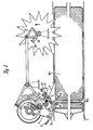
- Fig. 1 shows a in the pulling direction (Z) movable baler (1), which is to be attached to a tractor, not shown, and is driven by this via a PTO shaft.
- Z pulling direction
- S swath
- P press room
- G worm and eccentric gear
- the binding twine (F) is held at its beginning at the assigned knotter (2) above the bale and extends - drawn in broken lines - around the front of the bale to be created (B1).
- a star wheel (3) which is driven by the bale feed, are controlled by means of a toothed segment (31), when a predetermined bale length is reached and the piston (K) is retracted, the needles (N) are pivoted up to the knotters (2), where the twine (F) for knotting is detected, whereupon the needles are pivoted back and the disengaged toothed segment (31) returns to its initial position.
- the knot sensors (4) are arranged in the direction of the twine (F) of each twine loop near the knotter (2) above the bale (B1).
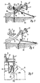
- Fig. 2 shows the arrangement of a knot sensor (4) in its position relative to the knotter (2) and the ball (B1), in the state after a knot has been formed on the knotter beak (21, 22) and cut off.
- the thread start (F2) of the tying of the next bale (B2) started is held close to the knotter (2).
- the twine (F, F2) is guided laterally in a slot (51) of a thread guide plate (5).
- the fork-shaped knot sensor (4) is arranged in front of the slit (51) in the thread start area of the knotted binding yarn (F), crossing it and pivoting in the direction of the knot's exit.
- a swivel position detector (41, 42) is located on the knot sensor (4) in such a swivel position that the knot sensor (4) reliably reaches when a knot runs out. Furthermore is located on the Tooth segment (31), which is used for knotter control, a cam (32), which actuates a changeover switch (33) depending on the further transport of a bale (B1).
- Fig. 3 shows again in detail the position of the binding thread (F) in the slot (51) and the fork of the knot sensor (4) before the knot in front of the knot beak (21, 22) has been pulled off by the bale (B1).
- the knot sensor (4) is pivoted by the retaining force of a spring (43) into such a position transversely to the twine (F) that its fork tines form an acute, approximately 60 degree, angle (W) with the twine start (F1).
- the swivel position indicator (42) is not actuated by the flag (41).
- FIG. 4 shows the device of FIG. 3 in a position with the bale moved further (B1), in which the knot has been pulled off the knot beak (21, 22) and is still caught in the fork prongs of the knot sensor (4). These are pivoted by the pull of the binding yarn (F), the flag (41) actuating the detector (42). The loop end (FO) only pulls the knot off the forks when the bale (B) is moved on.
- Fig. 5 shows a view of the knot sensor (4) in the direction of the arrow (V) of Fig. 3 with its fork tines (44, 45), the space (46) of which is designed to widen in the shape of an arc opposite to the thread entry direction (FE), and that with the slot (51) of the thread insert plate (5) in the upper end region of the slot (51) forms a thread catcher (47) for the twine (F), which is formed during the knot formation and the subsequent pivoting of the knot sensor (4) around the nose (55) shifted around the inside of the guide plate (5) through the slot (51) is formed. Only after a sufficient displacement of the thread strands in the direction of the thread catcher (47) of the slot (51) is the knot released into the fork (44, 45) and held there.
- twine (F) then has sufficient tension to pivot the knot sensor (4) against the force of the spring (43), which is not the case only when the twine or knot is open, no alarm is given. This ensures that only one node and each node actuates the sensor. Only after the bale has been transported further, as a result of which the knot sensor (4) is brought into a position in which contact actuation has taken place with certainty, can the end of the twine thread (F0) pull the knot off the fork. To ensure this, the fork tines (44, 45) are slightly bent against the bale transport direction, so that the knot remains in the fork (44, 45).
- the sensor contact is actuated for a correspondingly long time or via the correspondingly long bale transport path.
- the evaluation circuit determines this error state of the node formation by checking the contact message for a given bale path.
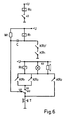
- FIG. 6 shows a circuit diagram of a preferred node testing device.
- a timer is started each time the node is actuated, during which time the node sensor must have reported an actuation, and if this was not the case, an alarm is triggered.
- the bale path is evaluated instead of a test time, for which purpose the driver (32), the the segment (31) which is driven by the star wheel (3) is arranged in each case in a bale position in which the knot must be removed from the knot with certainty and before the next knot is formed, actuates the changeover switch (33), in the event of a fault, the alarm indicators (60), which can consist of a signal lamp and a buzzer, are energized.
- the sensor contact (42) is followed by an auxiliary relay (Ro) so that its on and off states are available at the auxiliary relay contacts (KRo, KRo ').
- a first changeover contact (U1) of the changeover switch (42) switches on a first relay (R1) via a capacitor (C), which is then discharged via a resistor (W1), which is connected via a hold contact (KR1) with one of the auxiliary relay contacts (KRo ') itself holds until a node opens the sensor contact (42) and thereby the auxiliary relay contact (KRo').
- a second relay (R2) and the alarm indicators (60) are actuated via the normally open contact (KR1) of the first relay (R1) and continue via a latching contact ( KR2) and a delete key idle contact (T) held until it is actuated.
- This logic circuit can be varied with equivalent means by a person skilled in the art within the scope of the invention. If there are several knotters, an auxiliary relay is connected after them. The corresponding contacts (KRo ', KRo) are connected in parallel.
Landscapes
- Life Sciences & Earth Sciences (AREA)
- Environmental Sciences (AREA)
- Basic Packing Technique (AREA)
- Preliminary Treatment Of Fibers (AREA)
Claims (8)
Applications Claiming Priority (2)
| Application Number | Priority Date | Filing Date | Title |
|---|---|---|---|
| DE3813830 | 1988-04-23 | ||
| DE3813830A DE3813830A1 (de) | 1988-04-23 | 1988-04-23 | Knotenpruefer einer strohballenpresse |
Publications (2)
| Publication Number | Publication Date |
|---|---|
| EP0340397A1 EP0340397A1 (fr) | 1989-11-08 |
| EP0340397B1 true EP0340397B1 (fr) | 1991-09-25 |
Family
ID=6352784
Family Applications (1)
| Application Number | Title | Priority Date | Filing Date |
|---|---|---|---|
| EP89103055A Expired - Lifetime EP0340397B1 (fr) | 1988-04-23 | 1989-02-22 | Détecteur de fonctionnement du noueur d'une presse à balles |
Country Status (2)
| Country | Link |
|---|---|
| EP (1) | EP0340397B1 (fr) |
| DE (2) | DE3813830A1 (fr) |
Cited By (1)
| Publication number | Priority date | Publication date | Assignee | Title |
|---|---|---|---|---|
| US12129576B2 (en) | 2021-09-16 | 2024-10-29 | Belmont Textile Machinery Company | Automated yarn package handling system and method |
Families Citing this family (3)
| Publication number | Priority date | Publication date | Assignee | Title |
|---|---|---|---|---|
| DD297542A5 (de) * | 1990-09-07 | 1992-01-16 | Fortschritt Erntemaschinen Gmbh Neustadt In Sachsen,De | Vorrichtung zur kontrolle des bindevorganges |
| FR2691874B1 (fr) * | 1992-06-05 | 1999-01-29 | Greenland France Sa | Presse a fourrage. |
| DE19520762C2 (de) * | 1995-06-07 | 2000-04-13 | Claas Ohg | Prüfvorrichtung für eine Ballenschnürung |
Family Cites Families (4)
| Publication number | Priority date | Publication date | Assignee | Title |
|---|---|---|---|---|
| US4269116A (en) * | 1980-05-27 | 1981-05-26 | Gordon Goss E | Apparatus for detecting malfunction in tying operation on a baler |
| US4765235A (en) * | 1987-04-15 | 1988-08-23 | Hay & Forage Industries | Monitoring system for detecting malfunction of knotting mechanism on a crop baler |
| US4753463A (en) * | 1987-06-01 | 1988-06-28 | Ford New Holland, Inc. | Mistie detection and indication |
| US4753464A (en) * | 1987-06-01 | 1988-06-28 | Ford New Holland, Inc. | Mistie detector and indicator system |
-
1988
- 1988-04-23 DE DE3813830A patent/DE3813830A1/de active Granted
-
1989
- 1989-02-22 EP EP89103055A patent/EP0340397B1/fr not_active Expired - Lifetime
- 1989-02-22 DE DE8989103055T patent/DE58900313D1/de not_active Expired - Lifetime
Cited By (1)
| Publication number | Priority date | Publication date | Assignee | Title |
|---|---|---|---|---|
| US12129576B2 (en) | 2021-09-16 | 2024-10-29 | Belmont Textile Machinery Company | Automated yarn package handling system and method |
Also Published As
| Publication number | Publication date |
|---|---|
| DE58900313D1 (de) | 1991-11-07 |
| DE3813830C2 (fr) | 1990-02-15 |
| DE3813830A1 (de) | 1989-11-02 |
| EP0340397A1 (fr) | 1989-11-08 |
Similar Documents
| Publication | Publication Date | Title |
|---|---|---|
| DE2851035C2 (de) | Erntegut-Rundballenformmaschine | |
| DE1782821C3 (de) | Ladewagen mit einer ballenbildenden Ladeeinrichtung | |
| EP0157898B1 (fr) | Mécanisme de liage pour presses à balles rondes | |
| WO2013185832A2 (fr) | Dispositif de nouage de fils | |
| DE3150614A1 (de) | Automatische umschnuerungsvorrichtung an landwirtschaftlichen rollballenpressen | |
| DE2826904C2 (fr) | ||
| DE69804362T2 (de) | Knüpferüberwachungseinrichtung für Ballenpresse | |
| DE4132664C2 (de) | Verfahren zum Binden eines Ballens und Vorrichtung hierfür | |
| DE4116619C2 (de) | Vorrichtung zur Bildung eines Preßballens aus landwirtschaftlichem Erntegut | |
| EP0340397B1 (fr) | Détecteur de fonctionnement du noueur d'une presse à balles | |
| EP0197952A1 (fr) | Procede et dispositif pour la confection de bottes a partir de vegetaux coupes | |
| DE10047336A1 (de) | Ballenpresse für loses Preßgut | |
| DE102020120447B4 (de) | Knoterhaken für einen Garnknoter | |
| DE3918065C2 (fr) | ||
| EP1595443B1 (fr) | Dispositif pour ramasser et compacter des matières récoltées | |
| DE2330707A1 (de) | Automatische spulmaschine mit einer klemmvorrichtung | |
| DE2620807C2 (de) | Vorrichtung zum Umschnüren eines Rollballens aus landwirtschaftlichem Halmgut | |
| CH432318A (de) | Vorrichtung zum Sortieren von Hülsen mit und ohne Garnresten | |
| DE1535885A1 (de) | Knotenapparat | |
| EP3903562A1 (fr) | Dispositif de liaison pour une presse de récolte agricole et presse de récolte agricole dotée d'un tel dispositif de liaison | |
| DE102004023701A1 (de) | Maschine zum Aufnehmen und Pressen von landwirtschaftlichem Erntegut | |
| EP2837281B1 (fr) | Dispositif noueur pour une presse à balles | |
| EP0464651B1 (fr) | Presse pour grandes balles | |
| DE3019949C2 (fr) | ||
| EP0815719B1 (fr) | Presse à balles rondes |
Legal Events
| Date | Code | Title | Description |
|---|---|---|---|
| PUAI | Public reference made under article 153(3) epc to a published international application that has entered the european phase |
Free format text: ORIGINAL CODE: 0009012 |
|
| AK | Designated contracting states |
Kind code of ref document: A1 Designated state(s): BE DE FR NL |
|
| 17P | Request for examination filed |
Effective date: 19890922 |
|
| 17Q | First examination report despatched |
Effective date: 19901109 |
|
| GRAA | (expected) grant |
Free format text: ORIGINAL CODE: 0009210 |
|
| AK | Designated contracting states |
Kind code of ref document: B1 Designated state(s): BE DE FR NL |
|
| REF | Corresponds to: |
Ref document number: 58900313 Country of ref document: DE Date of ref document: 19911107 |
|
| ET | Fr: translation filed | ||
| PLBE | No opposition filed within time limit |
Free format text: ORIGINAL CODE: 0009261 |
|
| STAA | Information on the status of an ep patent application or granted ep patent |
Free format text: STATUS: NO OPPOSITION FILED WITHIN TIME LIMIT |
|
| 26N | No opposition filed | ||
| PGFP | Annual fee paid to national office [announced via postgrant information from national office to epo] |
Ref country code: NL Payment date: 19940228 Year of fee payment: 6 |
|
| PG25 | Lapsed in a contracting state [announced via postgrant information from national office to epo] |
Ref country code: NL Effective date: 19950901 |
|
| NLV4 | Nl: lapsed or anulled due to non-payment of the annual fee |
Effective date: 19950901 |
|
| PGFP | Annual fee paid to national office [announced via postgrant information from national office to epo] |
Ref country code: DE Payment date: 20020116 Year of fee payment: 14 |
|
| PGFP | Annual fee paid to national office [announced via postgrant information from national office to epo] |
Ref country code: FR Payment date: 20020221 Year of fee payment: 14 |
|
| PGFP | Annual fee paid to national office [announced via postgrant information from national office to epo] |
Ref country code: BE Payment date: 20020225 Year of fee payment: 14 |
|
| PG25 | Lapsed in a contracting state [announced via postgrant information from national office to epo] |
Ref country code: BE Free format text: LAPSE BECAUSE OF NON-PAYMENT OF DUE FEES Effective date: 20030228 |
|
| PG25 | Lapsed in a contracting state [announced via postgrant information from national office to epo] |
Ref country code: DE Free format text: LAPSE BECAUSE OF NON-PAYMENT OF DUE FEES Effective date: 20030902 |
|
| PG25 | Lapsed in a contracting state [announced via postgrant information from national office to epo] |
Ref country code: FR Free format text: LAPSE BECAUSE OF NON-PAYMENT OF DUE FEES Effective date: 20031031 |
|
| REG | Reference to a national code |
Ref country code: FR Ref legal event code: ST |