EP0340430A2 - Dispositif d'étanchéification - Google Patents
Dispositif d'étanchéification Download PDFInfo
- Publication number
- EP0340430A2 EP0340430A2 EP89104567A EP89104567A EP0340430A2 EP 0340430 A2 EP0340430 A2 EP 0340430A2 EP 89104567 A EP89104567 A EP 89104567A EP 89104567 A EP89104567 A EP 89104567A EP 0340430 A2 EP0340430 A2 EP 0340430A2
- Authority
- EP
- European Patent Office
- Prior art keywords
- sealing element
- longitudinal edge
- edge regions
- sealing
- curved
- Prior art date
- Legal status (The legal status is an assumption and is not a legal conclusion. Google has not performed a legal analysis and makes no representation as to the accuracy of the status listed.)
- Granted
Links
Images



Classifications
-
- F—MECHANICAL ENGINEERING; LIGHTING; HEATING; WEAPONS; BLASTING
- F16—ENGINEERING ELEMENTS AND UNITS; GENERAL MEASURES FOR PRODUCING AND MAINTAINING EFFECTIVE FUNCTIONING OF MACHINES OR INSTALLATIONS; THERMAL INSULATION IN GENERAL
- F16J—PISTONS; CYLINDERS; SEALINGS
- F16J15/00—Sealings
- F16J15/16—Sealings between relatively-moving surfaces
-
- F—MECHANICAL ENGINEERING; LIGHTING; HEATING; WEAPONS; BLASTING
- F16—ENGINEERING ELEMENTS AND UNITS; GENERAL MEASURES FOR PRODUCING AND MAINTAINING EFFECTIVE FUNCTIONING OF MACHINES OR INSTALLATIONS; THERMAL INSULATION IN GENERAL
- F16J—PISTONS; CYLINDERS; SEALINGS
- F16J15/00—Sealings
- F16J15/02—Sealings between relatively-stationary surfaces
- F16J15/06—Sealings between relatively-stationary surfaces with solid packing compressed between sealing surfaces
- F16J15/08—Sealings between relatively-stationary surfaces with solid packing compressed between sealing surfaces with exclusively metal packing
- F16J15/0887—Sealings between relatively-stationary surfaces with solid packing compressed between sealing surfaces with exclusively metal packing the sealing effect being obtained by elastic deformation of the packing
- F16J15/0893—Sealings between relatively-stationary surfaces with solid packing compressed between sealing surfaces with exclusively metal packing the sealing effect being obtained by elastic deformation of the packing the packing having a hollow profile
Definitions
- the invention relates to a device (according to the preamble of claim 1) for sealing the contact zone between a movable and a fixed system part.
- Devices of the type mentioned in the preamble of claim 1 serve, for example, to ensure a reliable gas-tight seal between a movable shut-off element (for example a swivel wing or a slide plate) of a hot gas pipeline of large size and a fixed seat.
- a movable shut-off element for example a swivel wing or a slide plate
- the invention is therefore based on the object to design a device according to the preamble of claim 1 so that the overall height of the sealing element is significantly reduced.
- a substantially simplified assembly and disassembly of the sealing element is also to be achieved.
- the sealing element contains at least one bend between the one longitudinal edge region and the curved zone and is otherwise shaped such that the two longitudinal edge regions lie one above the other and point to the same side.
- Such a configuration of the sealing element allows the spring stiffness of the sealing element desired for the respective application to be achieved with a minimal overall height.
- the assembly and disassembly of the sealing element is considerably simplified according to the invention.
- An expedient embodiment of the invention provides that the two longitudinal edge areas of the sealing element are firmly connected to one another and can be clamped together in the already connected state by means of the clamping device.
- the fixed connection of the two longitudinal edge areas and thus the arcuate curvature of the sealing element and the production of the spring tension can already be carried out in the factory with such a design.
- only the two longitudinal edge areas of the sealing element then need to be clamped together by means of the clamping device, which presents no difficulties in view of the fixed connection of these two longitudinal edge areas.
- the disassembly of the sealing element is also correspondingly simple, for example for the purpose of replacement.
- the sealing element 1 illustrated in FIG. 1 is formed by an elongated spring steel strip, which is illustrated in cross section in FIG. 1.
- It contains two flat longitudinal edge areas 2, 3 and a zone 4 which is arranged between these flat longitudinal edge areas and is curved in an arcuate manner transversely to the longitudinal direction of the spring steel strip.
- the two longitudinal edge regions 2 and 3 are of different lengths transversely to the longitudinal direction of the sealing element and point to the same side.
- the two longitudinal edge regions 2 and 3 are firmly connected to one another at certain intervals (perpendicular to the plane of the drawing in FIG. 1) by spot welds 7, 8, these welded connections absorbing the spring tension of the curved zone 4.
- through holes 9, 10 are also provided at certain intervals for receiving connecting elements.
- FIG. 2 shows the sealing element 1 according to FIG. 1 in the installed state.
- the flat longitudinal edge regions 2, 3 are in this case clamped between a stationary seat 11 and a terminal strip 12, the terminal strip 12 being connected to the stationary seat 11 via connecting elements 13.
- a movable shut-off element 14 cooperates with the fixed seat 11, which is formed, for example, by a pivotable wing or a slide plate and is movable in the direction of arrow 15.
- the sealing element 1 comes with a partial region of its curved zone 4 to bear against the shut-off element 14 and is thereby elastically deformed, as is illustrated in FIG. 2 by the dashed contour 1 '.
- the assembly and disassembly of the sealing element 1 is very simple and can easily be carried out by a single person.
- the longitudinal edge regions 2 and 3 of which are firmly connected to one another only the terminal strip 12 is placed and the flat longitudinal edge regions 2, 3 are clamped in by means of the connecting elements 13. Any necessary replacement of the sealing elements is correspondingly simple.
- the two longitudinal edge regions 2, 3 of the sealing element 1 are arranged transversely to the direction of movement (arrow 15) of the movable system part (shut-off element 14). This design results in a particularly low installation height H of the sealing element.
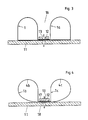
- two mirror-symmetrical sealing elements 1 and 1a are provided, which can be clamped by means of the same terminal block 12.
- a gaseous blocking agent for. B. sealing air to be introduced.
- two mirror-symmetrical sealing elements 1b, 1c are combined to form a one-piece double sealing element, the central region 17, 18 lying between the two curved zones 4b, 4c being clamped in by means of the clamping strip 12 and the connecting elements 13.
- the two middle areas 17, 18 of this double sealing element are firmly, preferably connected to one another by spot welding, so that they can be clamped together by means of the clamping device in the already connected state.
- FIG. 5 shows an exemplary embodiment in which the two longitudinal edge regions 2, 3 of the sealing element 1d are arranged parallel to the direction of movement (arrow 15) of the movable system part (shut-off element 14).
- the two longitudinal edge regions 2 and 3 which are firmly connected to one another, are clamped together by a clamping strip 12 and connecting elements 13.
- This design is characterized by a particularly small overall width B of the sealing element 1d.
- the two sealing elements 1e and 1f are fastened to the movable shut-off element 14, specifically by means of separate clamping strips 12e and 12f and connecting elements 13e and 13f.
- the two longitudinal edge regions of the sealing element are firmly connected to one another, preferably by spot welding, so that they can be clamped together with the clamping device in the already connected state.
- FIG. 7 shows an embodiment in which (similar to FIG. 4) sealing elements 1g and 1h are combined to form a one-piece double sealing element.
- the two sealing elements each contain (as in the arrangement according to FIGS. 1 and 2) two bends 5g, 6g and 5h, 6h, respectively, over which the central regions 17a, 18a (which here form the longitudinal edge regions) with the curved zones 4g and 4h are in communication.
- the area of the sealing elements 1g, 1h located between the two bends 5g, 6g and 5h, 6h is supported with part of its width on a support 20 or 21, which is adjustable in the direction of the arrows 22, 23.
- a support 20 or 21 which is adjustable in the direction of the arrows 22, 23.
- the spring force of the sealing elements 1g, 1h can be set within wide limits. For example, there is a much lower spring force, i. H. a softer spring behavior of the sealing element 1g when the support 20 is adjusted to the right.
- FIG. 8 A similar solution for changing the spring force is shown in FIG. 8.
- the sealing element 1d corresponds to the exemplary embodiment in FIG. 5.
- an angular clamping strip 12 ' is used, one leg of which is between the angled portions 25 and 26 of the sealing element only supported on part of its width. By changing the length of this leg, the spring force of the sealing element can be brought to the desired value in a simple manner.
- FIG. 9 illustrates how the joints at a corner can be designed in a sealing device composed of a plurality of sealing elements.
- the sealing element 1 ⁇ abuts the other sealing element 1 at an angle of about 90 °, the latter sealing element 1 still protruding somewhat beyond the joint.
- the sealing element 1 ⁇ has at its end facing the other sealing element 1 a thrust piece 1x, which overlaps with the main part 1y of the sealing element 1 ⁇ (overlap 26) and is freely displaceable in the axial direction of the sealing element 1 ⁇ for the purpose of adjustment. In this way, when the sealing device is installed, the thrust piece can be pushed up to the sealing element 1 once and can be clamped in this position with the associated terminal strip 12.
- the sealing elements 1 and 1 ⁇ come loose here, d. H. disconnected, to each other. A loose overlap between the main part 1y and the thrust piece 1x of the sealing element 1 ⁇ is also sufficient.
- the thrust piece 1x is cut out at its end facing the sealing element 1 in accordance with the contour of the sealing element 1, which leads to a reliable seal in the partial region of the curved zone which rests resiliently on a mating surface in the closed position of the movable system part.
- the sealing element facing the hot gas can be heated within the scope of the invention, which can be done, for example, by a heating coil or a hot air stream. If the critical zones of the sealing element are heated above the dew point temperature in this way, condensation phenomena and damage caused thereby are avoided.
- the elastic deformation illustrated in dashed lines in FIG. 2 on all outer sides of the circumference is particularly characteristic of the sealing element according to the invention. This results in a particularly large resilient circumferential length, which makes it possible to achieve the desired resilience of the sealing element with a significantly reduced overall height H.
Landscapes
- Engineering & Computer Science (AREA)
- General Engineering & Computer Science (AREA)
- Mechanical Engineering (AREA)
- Gasket Seals (AREA)
- Building Environments (AREA)
- Specific Sealing Or Ventilating Devices For Doors And Windows (AREA)
- Sealing Devices (AREA)
- Seal Device For Vehicle (AREA)
- Glass Compositions (AREA)
- Electrical Discharge Machining, Electrochemical Machining, And Combined Machining (AREA)
Priority Applications (1)
| Application Number | Priority Date | Filing Date | Title |
|---|---|---|---|
| AT89104567T ATE90429T1 (de) | 1988-05-05 | 1989-03-15 | Vorrichtung zur abdichtung. |
Applications Claiming Priority (2)
| Application Number | Priority Date | Filing Date | Title |
|---|---|---|---|
| DE3815402A DE3815402A1 (de) | 1988-05-05 | 1988-05-05 | Vorrichtung zur abdichtung |
| DE3815402 | 1988-05-05 |
Publications (3)
| Publication Number | Publication Date |
|---|---|
| EP0340430A2 true EP0340430A2 (fr) | 1989-11-08 |
| EP0340430A3 EP0340430A3 (fr) | 1991-01-23 |
| EP0340430B1 EP0340430B1 (fr) | 1993-06-09 |
Family
ID=6353750
Family Applications (1)
| Application Number | Title | Priority Date | Filing Date |
|---|---|---|---|
| EP89104567A Expired - Lifetime EP0340430B1 (fr) | 1988-05-05 | 1989-03-15 | Dispositif d'étanchéification |
Country Status (5)
| Country | Link |
|---|---|
| EP (1) | EP0340430B1 (fr) |
| AT (1) | ATE90429T1 (fr) |
| CA (1) | CA1338214C (fr) |
| DE (2) | DE3815402A1 (fr) |
| ES (1) | ES2041863T3 (fr) |
Cited By (5)
| Publication number | Priority date | Publication date | Assignee | Title |
|---|---|---|---|---|
| WO1995002136A1 (fr) * | 1993-07-08 | 1995-01-19 | Mannesmann Aktiengesellschaft | Dispositif permettant d'assurer l'etancheite entre deux parties d'une installation |
| EP0622588A3 (fr) * | 1993-04-28 | 1995-04-05 | Stober & Morlock | Dispositif d'obturation pour conduites avec grande section transversale, en particulier conduites pour gaz d'échappement et gaz de fumée d'une centrale. |
| EP0689010A3 (fr) * | 1994-06-22 | 1996-09-18 | Mannesmann Ag | Dispositif d'étanchéité pour une soupape de fumée |
| EP1092899A2 (fr) | 1999-10-13 | 2001-04-18 | Janich GmbH & Co. | Dispositif d'étanchéité |
| CN110307353A (zh) * | 2019-06-15 | 2019-10-08 | 宁波连通设备集团有限公司 | 密封结构、密封系统及闸板阀 |
Families Citing this family (8)
| Publication number | Priority date | Publication date | Assignee | Title |
|---|---|---|---|---|
| DE4030611A1 (de) * | 1990-09-27 | 1992-04-02 | Mannesmann Ag | Absperrorgan |
| DE4204516C1 (en) * | 1992-02-15 | 1993-09-02 | Langerbein-Scharf Gmbh & Co. Kg, 4700 Hamm, De | Gas-conduit stop valve - has U=section rust-proof-steel distance-strip securing ends of U=shaped sealing strip and enclosing base strip |
| DE19515014A1 (de) * | 1995-04-24 | 1996-10-31 | Linde Ag | Absperrarmatur mit einer Drehklappe |
| DE19521915A1 (de) * | 1995-06-09 | 1996-12-12 | Mannesmann Ag | Vorrichtung zur Abdichtung zwischen beweglichen Anlagenteilen |
| DE19521916A1 (de) * | 1995-06-09 | 1996-12-12 | Mannesmann Ag | Vorrichtung zur Abdichtung zwischen beweglichen Anlagenteilen |
| DE19540410A1 (de) * | 1995-10-30 | 1997-05-07 | Adams Armaturen Gmbh | Metallische Dichtung für Absperrventile |
| DE19828896C1 (de) * | 1998-06-19 | 1999-09-09 | Mannesmann Ag | Vorrichtung zur Abdichtung |
| PL70978Y1 (pl) * | 2017-11-09 | 2019-09-30 | Dsm Spolka Z Ograniczona Odpowiedzialnoscia | Uszczelnienie sprężyste klapy |
Family Cites Families (11)
| Publication number | Priority date | Publication date | Assignee | Title |
|---|---|---|---|---|
| DE7523443U (de) * | 1977-02-24 | Elring Dichtungswerke Kg, 7417 Dettingen | Flachdichtung | |
| US1770548A (en) * | 1926-10-04 | 1930-07-15 | Victor Mfg & Gasket Co | Gasket |
| DE688556C (de) * | 1937-07-01 | 1940-02-23 | Fried Krupp Akt Ges | Absperrschieber fuer Gasleitungen |
| DE685037C (de) * | 1937-07-01 | 1939-12-09 | Fried Krupp Akt Ges | Absperrschieber fuer Gasleitungen o. dgl. |
| DE1650568A1 (de) * | 1967-09-05 | 1970-10-01 | Thermo Technical Dev Ltd | Absperrschieber-Anordnung zur gasdichten Unterteilung von Gaskanaelen und -leitungen |
| FR2119258A5 (fr) * | 1970-12-24 | 1972-08-04 | Joint Francais | |
| DE2502240A1 (de) * | 1975-01-21 | 1976-07-22 | Steege & Janich Kg | Absperrvorrichtung fuer rohrleitungen |
| DE2903724C2 (de) * | 1979-01-31 | 1983-01-13 | PKS-Engineering GmbH & Co KG, 4720 Beckum | Rohrleitungsschieber |
| FR2480892A1 (fr) * | 1980-04-18 | 1981-10-23 | Ferodo Sa | Dispositif formant etancheite au debouche d'une canalisation, par exemple d'un boitier d'une installation de chauffage de l'habitacle d'un vehicule automobile |
| DD250566A1 (de) * | 1986-06-30 | 1987-10-14 | Magdeburger Armaturenwerke | Metalldichtende absperrklappe |
| DE8800255U1 (de) * | 1988-01-12 | 1988-02-25 | Karl zur Steege GmbH & Co., 4130 Moers | Absperrarmatur |
-
1988
- 1988-05-05 DE DE3815402A patent/DE3815402A1/de not_active Withdrawn
-
1989
- 1989-03-15 ES ES198989104567T patent/ES2041863T3/es not_active Expired - Lifetime
- 1989-03-15 DE DE8989104567T patent/DE58904597D1/de not_active Expired - Fee Related
- 1989-03-15 AT AT89104567T patent/ATE90429T1/de not_active IP Right Cessation
- 1989-03-15 EP EP89104567A patent/EP0340430B1/fr not_active Expired - Lifetime
- 1989-04-18 CA CA000596986A patent/CA1338214C/fr not_active Expired - Fee Related
Cited By (8)
| Publication number | Priority date | Publication date | Assignee | Title |
|---|---|---|---|---|
| EP0622588A3 (fr) * | 1993-04-28 | 1995-04-05 | Stober & Morlock | Dispositif d'obturation pour conduites avec grande section transversale, en particulier conduites pour gaz d'échappement et gaz de fumée d'une centrale. |
| WO1995002136A1 (fr) * | 1993-07-08 | 1995-01-19 | Mannesmann Aktiengesellschaft | Dispositif permettant d'assurer l'etancheite entre deux parties d'une installation |
| US5667226A (en) * | 1993-07-08 | 1997-09-16 | Mannesmann Aktiengesellschaft | Device for providing a seal between two parts of an installation |
| CN1038357C (zh) * | 1993-07-08 | 1998-05-13 | 曼内斯曼有限公司 | 两个可相对运动的部件之间的密封装置 |
| EP0689010A3 (fr) * | 1994-06-22 | 1996-09-18 | Mannesmann Ag | Dispositif d'étanchéité pour une soupape de fumée |
| EP1092899A2 (fr) | 1999-10-13 | 2001-04-18 | Janich GmbH & Co. | Dispositif d'étanchéité |
| US6588768B1 (en) | 1999-10-13 | 2003-07-08 | Janich Gmbh & Co. | Device for sealing |
| CN110307353A (zh) * | 2019-06-15 | 2019-10-08 | 宁波连通设备集团有限公司 | 密封结构、密封系统及闸板阀 |
Also Published As
| Publication number | Publication date |
|---|---|
| ES2041863T3 (es) | 1993-12-01 |
| EP0340430A3 (fr) | 1991-01-23 |
| ATE90429T1 (de) | 1993-06-15 |
| DE3815402A1 (de) | 1989-11-16 |
| EP0340430B1 (fr) | 1993-06-09 |
| CA1338214C (fr) | 1996-04-02 |
| DE58904597D1 (de) | 1993-07-15 |
Similar Documents
| Publication | Publication Date | Title |
|---|---|---|
| EP0340430B1 (fr) | Dispositif d'étanchéification | |
| EP0175856B1 (fr) | Collier de serrage avec vis tendeuse | |
| EP0186728B1 (fr) | Manchon de serrage pour tuyaux | |
| DE69209627T2 (de) | Schnellverbindungseinrichtung zur dichten Verbindung zweier Leitungen oder zweier starrer oder halbstarrer Rohre | |
| DE2640258A1 (de) | Bolzenfreie abstandhalter | |
| EP0057373B1 (fr) | Manchon de serrage pour tuyaux | |
| EP0681097B1 (fr) | Elément de connexion flexible pour éléments tubulaires | |
| EP0816738B1 (fr) | Dispositif de découplement pour vibrations dans conduits | |
| EP0035526B1 (fr) | Dispositif pour la fixation de parties d'installation oblongues et notamment de profiles et de tuyaux en matiere plastique | |
| DE3347503C2 (de) | Selbstsichernder Sperrbolzen | |
| DE2314710A1 (de) | Dichtung fuer einen umlaufenden regenerativ-waermeaustauscher | |
| EP0174486A2 (fr) | Dispositif pour l'arrêt d'un conduit | |
| EP0173805B1 (fr) | Dispositif d'avance rectiligne | |
| DE2646085C2 (de) | In seiner Länge verstellbares Spiegelisolierelement | |
| DE19515533A1 (de) | Heizflansch, insbesondere zum Vorwärmen von Luft in einem Saugrohr einer Brennkraftmaschine | |
| AT390524B (de) | Verfahren zur herstellung eines mehrphasigen thermischen ausloesers sowie ein nach diesem verfahren herstellbarer ausloeser | |
| DE1184419B (de) | Mehrfachrelais | |
| EP1030986B1 (fr) | Dispositif pour realiser une etancheite | |
| DE3301229A1 (de) | Breitbandschelle zum abgedichteten verbinden von glattzylindrischen rohrenden, insbesondere von abwasserrohren mittels eines dichtungselements | |
| DE3127758C2 (de) | Vorrichtung zur Verbindung von mit Flanschen versehenen Kunststoffrohren | |
| EP0668463A1 (fr) | Dispositif d'espacement | |
| DE3910403A1 (de) | Gliederarmband | |
| DE19906174C1 (de) | Vorrichtung zur Abdichtung | |
| DE933903C (de) | Rohrkupplung, insbesondere zur Verbindung starrer Rohre | |
| DE102023127521A1 (de) | Vorrichtung zur Temperierung eines Raumes |
Legal Events
| Date | Code | Title | Description |
|---|---|---|---|
| PUAI | Public reference made under article 153(3) epc to a published international application that has entered the european phase |
Free format text: ORIGINAL CODE: 0009012 |
|
| AK | Designated contracting states |
Kind code of ref document: A2 Designated state(s): AT BE CH DE ES FR GB IT LI NL SE |
|
| PUAL | Search report despatched |
Free format text: ORIGINAL CODE: 0009013 |
|
| AK | Designated contracting states |
Kind code of ref document: A3 Designated state(s): AT BE CH DE ES FR GB IT LI NL SE |
|
| RHK1 | Main classification (correction) |
Ipc: F16J 15/08 |
|
| 17P | Request for examination filed |
Effective date: 19910326 |
|
| RAP1 | Party data changed (applicant data changed or rights of an application transferred) |
Owner name: MANNESMANN AKTIENGESELLSCHAFT |
|
| 17Q | First examination report despatched |
Effective date: 19921201 |
|
| GRAA | (expected) grant |
Free format text: ORIGINAL CODE: 0009210 |
|
| AK | Designated contracting states |
Kind code of ref document: B1 Designated state(s): AT BE CH DE ES FR GB IT LI NL SE |
|
| PG25 | Lapsed in a contracting state [announced via postgrant information from national office to epo] |
Ref country code: SE Effective date: 19930609 |
|
| REF | Corresponds to: |
Ref document number: 90429 Country of ref document: AT Date of ref document: 19930615 Kind code of ref document: T |
|
| REF | Corresponds to: |
Ref document number: 58904597 Country of ref document: DE Date of ref document: 19930715 |
|
| ITF | It: translation for a ep patent filed | ||
| ET | Fr: translation filed | ||
| GBT | Gb: translation of ep patent filed (gb section 77(6)(a)/1977) |
Effective date: 19930813 |
|
| REG | Reference to a national code |
Ref country code: ES Ref legal event code: FG2A Ref document number: 2041863 Country of ref document: ES Kind code of ref document: T3 |
|
| PG25 | Lapsed in a contracting state [announced via postgrant information from national office to epo] |
Ref country code: AT Effective date: 19940315 |
|
| PG25 | Lapsed in a contracting state [announced via postgrant information from national office to epo] |
Ref country code: LI Effective date: 19940331 Ref country code: CH Effective date: 19940331 |
|
| PLBE | No opposition filed within time limit |
Free format text: ORIGINAL CODE: 0009261 |
|
| STAA | Information on the status of an ep patent application or granted ep patent |
Free format text: STATUS: NO OPPOSITION FILED WITHIN TIME LIMIT |
|
| 26N | No opposition filed | ||
| REG | Reference to a national code |
Ref country code: CH Ref legal event code: PL |
|
| PGFP | Annual fee paid to national office [announced via postgrant information from national office to epo] |
Ref country code: FR Payment date: 20000228 Year of fee payment: 12 |
|
| PGFP | Annual fee paid to national office [announced via postgrant information from national office to epo] |
Ref country code: GB Payment date: 20000313 Year of fee payment: 12 |
|
| PGFP | Annual fee paid to national office [announced via postgrant information from national office to epo] |
Ref country code: DE Payment date: 20000315 Year of fee payment: 12 |
|
| PGFP | Annual fee paid to national office [announced via postgrant information from national office to epo] |
Ref country code: NL Payment date: 20000320 Year of fee payment: 12 |
|
| PGFP | Annual fee paid to national office [announced via postgrant information from national office to epo] |
Ref country code: ES Payment date: 20000327 Year of fee payment: 12 |
|
| PGFP | Annual fee paid to national office [announced via postgrant information from national office to epo] |
Ref country code: BE Payment date: 20000405 Year of fee payment: 12 |
|
| PG25 | Lapsed in a contracting state [announced via postgrant information from national office to epo] |
Ref country code: GB Free format text: LAPSE BECAUSE OF NON-PAYMENT OF DUE FEES Effective date: 20010315 |
|
| PG25 | Lapsed in a contracting state [announced via postgrant information from national office to epo] |
Ref country code: ES Free format text: LAPSE BECAUSE OF NON-PAYMENT OF DUE FEES Effective date: 20010316 |
|
| PG25 | Lapsed in a contracting state [announced via postgrant information from national office to epo] |
Ref country code: DE Free format text: LAPSE BECAUSE OF NON-PAYMENT OF DUE FEES Effective date: 20010331 Ref country code: BE Free format text: LAPSE BECAUSE OF NON-PAYMENT OF DUE FEES Effective date: 20010331 |
|
| BERE | Be: lapsed |
Owner name: MANNESMANN A.G. Effective date: 20010331 |
|
| PG25 | Lapsed in a contracting state [announced via postgrant information from national office to epo] |
Ref country code: NL Free format text: LAPSE BECAUSE OF NON-PAYMENT OF DUE FEES Effective date: 20011001 |
|
| GBPC | Gb: european patent ceased through non-payment of renewal fee |
Effective date: 20010315 |
|
| PG25 | Lapsed in a contracting state [announced via postgrant information from national office to epo] |
Ref country code: FR Free format text: LAPSE BECAUSE OF NON-PAYMENT OF DUE FEES Effective date: 20011130 |
|
| NLV4 | Nl: lapsed or anulled due to non-payment of the annual fee |
Effective date: 20011001 |
|
| REG | Reference to a national code |
Ref country code: FR Ref legal event code: ST |
|
| REG | Reference to a national code |
Ref country code: ES Ref legal event code: FD2A Effective date: 20030303 |
|
| PG25 | Lapsed in a contracting state [announced via postgrant information from national office to epo] |
Ref country code: IT Free format text: LAPSE BECAUSE OF NON-PAYMENT OF DUE FEES Effective date: 20050315 |