EP0340431A1 - Dispositif de transmission entre la boîte de vitesse et l'essieu arrière - Google Patents
Dispositif de transmission entre la boîte de vitesse et l'essieu arrière Download PDFInfo
- Publication number
- EP0340431A1 EP0340431A1 EP89104659A EP89104659A EP0340431A1 EP 0340431 A1 EP0340431 A1 EP 0340431A1 EP 89104659 A EP89104659 A EP 89104659A EP 89104659 A EP89104659 A EP 89104659A EP 0340431 A1 EP0340431 A1 EP 0340431A1
- Authority
- EP
- European Patent Office
- Prior art keywords
- rear axle
- shaft
- homokinetic
- drive connection
- axle
- Prior art date
- Legal status (The legal status is an assumption and is not a legal conclusion. Google has not performed a legal analysis and makes no representation as to the accuracy of the status listed.)
- Granted
Links
Images
Classifications
-
- B—PERFORMING OPERATIONS; TRANSPORTING
- B60—VEHICLES IN GENERAL
- B60K—ARRANGEMENT OR MOUNTING OF PROPULSION UNITS OR OF TRANSMISSIONS IN VEHICLES; ARRANGEMENT OR MOUNTING OF PLURAL DIVERSE PRIME-MOVERS IN VEHICLES; AUXILIARY DRIVES FOR VEHICLES; INSTRUMENTATION OR DASHBOARDS FOR VEHICLES; ARRANGEMENTS IN CONNECTION WITH COOLING, AIR INTAKE, GAS EXHAUST OR FUEL SUPPLY OF PROPULSION UNITS IN VEHICLES
- B60K17/00—Arrangement or mounting of transmissions in vehicles
- B60K17/22—Arrangement or mounting of transmissions in vehicles characterised by arrangement, location, or type of main drive shafting, e.g. cardan shaft
-
- B—PERFORMING OPERATIONS; TRANSPORTING
- B60—VEHICLES IN GENERAL
- B60K—ARRANGEMENT OR MOUNTING OF PROPULSION UNITS OR OF TRANSMISSIONS IN VEHICLES; ARRANGEMENT OR MOUNTING OF PLURAL DIVERSE PRIME-MOVERS IN VEHICLES; AUXILIARY DRIVES FOR VEHICLES; INSTRUMENTATION OR DASHBOARDS FOR VEHICLES; ARRANGEMENTS IN CONNECTION WITH COOLING, AIR INTAKE, GAS EXHAUST OR FUEL SUPPLY OF PROPULSION UNITS IN VEHICLES
- B60K17/00—Arrangement or mounting of transmissions in vehicles
- B60K17/32—Arrangement or mounting of transmissions in vehicles the ultimate propulsive elements, e.g. ground wheels, being rockable about a horizontal pivot
Definitions
- the invention relates to a drive connection between the transmission and the driven rear axle of a commercial vehicle, in particular an articulated truck with an underfloor construction of the motor-transmission unit, the transmission output shaft being connected to the rear axle input shaft via a homokinetic drive shaft shielded from external influences.
- Drive connections of this type are known, wherein the drive shaft connecting the transmission and the rear axle, as a result of deflection or rebound of the rear axle, takes place in the spline toothing that connects the two homokinetic joints of the drive shaft.
- the rotation-free, center-centered arrangement of the bellows shielding the drive shaft against external influences requires a not inconsiderable amount of additional components.
- the invention has for its object to arrange the transmission and rear axle of a commercial vehicle and to connect by means of a protected against environmental influences homokinetic propeller shaft that a minimized distance between the transmission and the rear axle is achieved.
- axle swing arm which is fastened to the longitudinal frame of the vehicle via a support bracket, supports the rear axle and by means of a spring relative to the longitudinal axis of the vehicle frame supported, is articulated in a point (A) on or near the drive center axis ED (of the transmission output shaft and rear axle shaft) and as a connecting element between the transmission output shaft and the rear axle input shaft, a propeller shaft with a known homokinetic fixed bearing and a known homokinetic floating bearing is arranged such that the fixed bearing, pivotally mounted in (B), on the transmission output shaft and the axially displaceable floating bearing, pivotally mounted in (C), is arranged on the rear axle input shaft, the resulting deflection angle ( ⁇ ) of the gearbox-side fixed bearing being greater than the resulting diffraction angle ( ⁇ ) of the non-locating bearing on the rear axle.
- Homokinetic spherical plain bearings generally allow large diffraction angles, such as are necessary when the height of the rear axle is offset from the gearbox due to the compression and rebound of the rear axle. These diffraction angles are effortlessly realized with conventional homokinetic cardan shafts, however, the length compensation must take place via a shaft-sleeve connection with spline toothing connecting the two homokinetic joints, which requires a relatively long cardan shaft, as well as considerable wear in the spline toothing.
- the device according to the invention builds optimally short without such a length compensation. This is made possible by a specific geometric assignment of the gearbox, axle swing arm and rear axle, which requires the use of a known homokinetic fixed bearing with a large diffraction angle on the Gearbox side and a known homokinetic floating bearing with a smaller diffraction angle, but also allow for additional length compensation on the rear axle side, whereby the fixed bearing and floating bearing can be connected so close that they almost touch in maximum deflection.
- a swing arm linkage "A" aligned with the drive train "ED" is essential. The closer the center of the joint "B" is to the pivot point "A", the smaller the diffraction angles ⁇ and ⁇ and the sliding path "S".
- Pivot point “C” is structurally determined by the required distance from the gear unit.
- Articulation point “A” is structurally determined by the requirements of the kinematics of axle deflection and the spring travel of the air spring as well as by stress and space.
- the spring kinematics of the axle linkage and the position of the drive train mean that the diffraction angles " ⁇ 1" and “ ⁇ 2" at the floating bearing are always smaller than the diffraction angles " ⁇ 1" and “ ⁇ 2" at the fixed bearing.
- the floating bearing with sliding path "s" and a smaller flexion angle “ ⁇ mul” is arranged at the center of the joint" C ".
- the permissible flexion angles" ⁇ 1 "and” ⁇ 2 determine the distances BC1 and BC2 of the two spherical bearings. This also results in the diffraction angles " ⁇ 1” or " ⁇ ⁇ of the fixed joint at the center of the joint” B ".
- the sliding paths s1 and S2 in turn result from the difference in curvature of the arcs AC - BC.
- the articulation point "A" of the axle rocker is shifted relative to the drive center axis "ED" in such a way that when the axle is deflected resulting deflection angle " ⁇ 1" and “ ⁇ 2" are the same. In this way, the permissible diffraction angle " ⁇ " is optimally evaluated, and there is still uniform wear on the joints.
- the homokinetic fixed bearing consists of an outer part fastened to the transmission output shaft and an inner part, which is connected via a shaft with the interposition of a spacer sleeve to the inner part of the homokinetic floating bearing, the outer part of which is fixed via a flange to the Rear axle input shaft is connected.
- the installation space between the transmission and the rear axle is kept small, so that optimal conditions are created for the installation of a motor-transmission unit in the underfloor construction in vehicles with a short wheelbase.
- the assembly conditions for the independently installable outer and inner parts of the joints, which are then connected to one another by a separate connecting shaft, are particularly favorable.
- cover tubes are fastened to the transmission housing and rear axle housing, and a cover tube is also overlapped by a divided cover cap, one cover tube and the cover cap being connected by means of a bellows. Due to the low diffraction angle of the homokinetic bearings compared to known designs, the bellows does not have to fold out as far. So he can simpler, ie with fewer folds. It is also not subject to such high flex wear. Furthermore, the divisible cover cap ensures quick and easy access to the constant velocity joints if necessary.
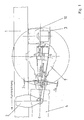
- FIG. 1 shows a vehicle side member 1 with a mounting bracket 2 attached to it, in the articulation point A of which the axle rocker 3 is suspended, which is supported by air spring 10 with respect to the side member 1.
- the rear axle 7 is arranged on the axle rocker 3, the drive center axis ED leading from the transmission center plane E to the rear axis center plane D.
- the articulation point A of the axle rocker 3 lies on or in the vicinity of the drive center plane ED.
- the transmission output and the rear axle input are connected by means of a homokinetic drive shaft 11 (FIGS. 2 and 3) which is not visible in FIG. 1, B being the transmission center and C the rear axle center point.
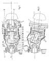
- FIGS. 2 and 3 show the homokinetic cardan shaft 11 in association with the gearbox 4 and rear axle 7, FIG. 2 showing the idle state, FIG. 3 the sprung or sprung state.
- the homokinetic propeller shaft 11 consists of a homokinetic fixed bearing 12 and a homokinetic floating bearing 13, which are connected to one another via a shaft 18, their axial distance being established via a spacer bushing 19 and their axial fixation via locking rings 20, 21.
- the fixed bearing 12 has a larger diffraction angle than the floating bearing 13, which, however, allows a small axial displacement (s).
- Fixed bearing 12 consists of an outer part 14 which is fixedly connected to the transmission output shaft 6, and an inner part 15 which, for example is fixed via teeth on the shaft 18.
- Floating bearing 13 consists of an outer part 16, which is fixedly connected to the rear axle shaft 9 via flange 22 and spacer 29, and an inner part 17, which is fastened to the shaft 18, for example, by toothing.
- the rotation-free cover tube 23 is fixed on the transmission housing 5, and the rotation-free cover tube 24 is fixed on the rear axle housing 8.
- a divided cover cap 25 with a curved outlet 30 is arranged, which overlaps the floating bearing 13.
- One end of the bellows 26, which protects the homokinetic joints 12, 13 against dirt, is lashed onto the cover tube 24 and cover cap 25 by means of clamps 27, 28. The bellows 26 is protected from the rotating joint parts when the rear axle is deflected or rebounded by the curved outlet 30 of the cover cap 25.
- the clamps 27, 28 are released and the bellows 26 is shifted towards the transmission 4. Then the divided cap 25 can be lifted off so that the constant velocity joints 12 and 13 are exposed and accessible for maintenance and disassembly.
Landscapes
- Engineering & Computer Science (AREA)
- Chemical & Material Sciences (AREA)
- Combustion & Propulsion (AREA)
- Transportation (AREA)
- Mechanical Engineering (AREA)
- Automatic Cycles, And Cycles In General (AREA)
- Axle Suspensions And Sidecars For Cycles (AREA)
- Heat Treatment Of Sheet Steel (AREA)
- General Details Of Gearings (AREA)
- Shafts, Cranks, Connecting Bars, And Related Bearings (AREA)
Priority Applications (1)
| Application Number | Priority Date | Filing Date | Title |
|---|---|---|---|
| AT89104659T ATE59020T1 (de) | 1988-04-30 | 1989-03-16 | Antriebsverbindung zwischen dem getriebe und der hinterachse. |
Applications Claiming Priority (2)
| Application Number | Priority Date | Filing Date | Title |
|---|---|---|---|
| DE3814709 | 1988-04-30 | ||
| DE3814709A DE3814709C1 (fr) | 1988-04-30 | 1988-04-30 |
Publications (2)
| Publication Number | Publication Date |
|---|---|
| EP0340431A1 true EP0340431A1 (fr) | 1989-11-08 |
| EP0340431B1 EP0340431B1 (fr) | 1990-12-12 |
Family
ID=6353302
Family Applications (1)
| Application Number | Title | Priority Date | Filing Date |
|---|---|---|---|
| EP89104659A Expired - Lifetime EP0340431B1 (fr) | 1988-04-30 | 1989-03-16 | Dispositif de transmission entre la boîte de vitesse et l'essieu arrière |
Country Status (3)
| Country | Link |
|---|---|
| EP (1) | EP0340431B1 (fr) |
| AT (1) | ATE59020T1 (fr) |
| DE (2) | DE3814709C1 (fr) |
Citations (3)
| Publication number | Priority date | Publication date | Assignee | Title |
|---|---|---|---|---|
| US3123171A (en) * | 1958-11-28 | 1964-03-03 | Vehicle | |
| GB1159277A (en) * | 1966-02-02 | 1969-07-23 | Ford Motor Co | Motor Vehicle Suspensions |
| FR2441506A1 (fr) * | 1978-11-14 | 1980-06-13 | Gkn Group Services Ltd | Vehicule automobile a transmission par pont |
Family Cites Families (3)
| Publication number | Priority date | Publication date | Assignee | Title |
|---|---|---|---|---|
| GB1339751A (en) * | 1969-12-11 | 1973-12-05 | Gkn Transmissions Ltd | Propeller shaft assemblies |
| FR2550139B1 (fr) * | 1983-08-02 | 1985-11-29 | Glaenzer Spicer Sa | Dispositif de transmission perfectionne, a joint double, notamment pour vehicule |
| DE3704143A1 (de) * | 1987-02-11 | 1988-08-25 | Man Nutzfahrzeuge Gmbh | Gelenkkupplung |
-
1988
- 1988-04-30 DE DE3814709A patent/DE3814709C1/de not_active Expired
-
1989
- 1989-03-16 EP EP89104659A patent/EP0340431B1/fr not_active Expired - Lifetime
- 1989-03-16 DE DE8989104659T patent/DE58900033D1/de not_active Expired - Lifetime
- 1989-03-16 AT AT89104659T patent/ATE59020T1/de not_active IP Right Cessation
Patent Citations (3)
| Publication number | Priority date | Publication date | Assignee | Title |
|---|---|---|---|---|
| US3123171A (en) * | 1958-11-28 | 1964-03-03 | Vehicle | |
| GB1159277A (en) * | 1966-02-02 | 1969-07-23 | Ford Motor Co | Motor Vehicle Suspensions |
| FR2441506A1 (fr) * | 1978-11-14 | 1980-06-13 | Gkn Group Services Ltd | Vehicule automobile a transmission par pont |
Also Published As
| Publication number | Publication date |
|---|---|
| ATE59020T1 (de) | 1990-12-15 |
| EP0340431B1 (fr) | 1990-12-12 |
| DE58900033D1 (de) | 1991-01-24 |
| DE3814709C1 (fr) | 1989-08-24 |
Similar Documents
| Publication | Publication Date | Title |
|---|---|---|
| DE3507432A1 (de) | Aufhaengung fuer eine antriebsachse eines kraftfahrzeuges | |
| DE3140540C2 (fr) | ||
| DE2748359A1 (de) | Antriebseinrichtung fuer schiffe | |
| EP3272614B1 (fr) | Train de roulement pour un véhicule sur rail | |
| EP1940667A1 (fr) | Transmission a joint a double cardan de vehicules sur rails | |
| DE3514146C2 (fr) | ||
| EP0514754B1 (fr) | Accouplement à grande élasticité en torsion | |
| EP0340431B1 (fr) | Dispositif de transmission entre la boîte de vitesse et l'essieu arrière | |
| DE19702682A1 (de) | Achs- und/oder Winkelversatz ausgleichender Antriebsverbindung | |
| DE3615858C2 (de) | Radantrieb für Kraftfahrzeuge | |
| EP1028046A2 (fr) | Elément coulissant combiné avec découplage de vibrations | |
| DE19819467A1 (de) | Drehgestell für Schienenfahrzeuge | |
| DE2824241A1 (de) | Trieb- und fahrwerksanordnung fuer kraftfahrzeuge | |
| EP0724522B1 (fr) | Transmission comportant un moteur d'entrainement, une boite de vitesses et un essieu pour vehicule automobile | |
| DE2923312C2 (de) | Kraftleitung zwischen der Abtriebswelle einer Antriebseinheit, insbesondere eines Dieselmotors, und dem Vorderrad eines Kraftfahrzeuges mit Vorderradantrieb | |
| AT527594B1 (de) | Antrieb und Fahrwerk für ein Schienenfahrzeug | |
| DE3411746C1 (de) | Allradantrieb fuer Kraftfahrzeuge | |
| DE102018130021A1 (de) | Antriebsanordnung eines Kraftfahrzeugs mit einem Elektromotor | |
| DE102013210235A1 (de) | Drehmomentstütze für ein Schienenfahrzeug | |
| EP0245645A1 (fr) | Arbre articulé avec deux joints de cardan | |
| DE2605458A1 (de) | Abdichtung fuer eine wellengelenkkupplung | |
| DE3149471A1 (de) | Doppelachsantrieb fuer schienentriebfahrzeuge | |
| DE102017221585A1 (de) | Radaufhängung für ein zweispuriges Fahrzeug | |
| DE3704143C2 (fr) | ||
| DE3218831A1 (de) | Angetriebene verbundlenker-hinterachse |
Legal Events
| Date | Code | Title | Description |
|---|---|---|---|
| PUAI | Public reference made under article 153(3) epc to a published international application that has entered the european phase |
Free format text: ORIGINAL CODE: 0009012 |
|
| AK | Designated contracting states |
Kind code of ref document: A1 Designated state(s): AT CH DE GB IT LI SE |
|
| 17P | Request for examination filed |
Effective date: 19891205 |
|
| 17Q | First examination report despatched |
Effective date: 19900514 |
|
| ITF | It: translation for a ep patent filed | ||
| GRAA | (expected) grant |
Free format text: ORIGINAL CODE: 0009210 |
|
| AK | Designated contracting states |
Kind code of ref document: B1 Designated state(s): AT CH DE GB IT LI SE |
|
| REF | Corresponds to: |
Ref document number: 59020 Country of ref document: AT Date of ref document: 19901215 Kind code of ref document: T |
|
| GBT | Gb: translation of ep patent filed (gb section 77(6)(a)/1977) | ||
| REF | Corresponds to: |
Ref document number: 58900033 Country of ref document: DE Date of ref document: 19910124 |
|
| ITTA | It: last paid annual fee | ||
| PLBE | No opposition filed within time limit |
Free format text: ORIGINAL CODE: 0009261 |
|
| STAA | Information on the status of an ep patent application or granted ep patent |
Free format text: STATUS: NO OPPOSITION FILED WITHIN TIME LIMIT |
|
| 26N | No opposition filed | ||
| PGFP | Annual fee paid to national office [announced via postgrant information from national office to epo] |
Ref country code: CH Payment date: 19940131 Year of fee payment: 6 |
|
| PGFP | Annual fee paid to national office [announced via postgrant information from national office to epo] |
Ref country code: AT Payment date: 19940203 Year of fee payment: 6 |
|
| PGFP | Annual fee paid to national office [announced via postgrant information from national office to epo] |
Ref country code: GB Payment date: 19940308 Year of fee payment: 6 |
|
| EAL | Se: european patent in force in sweden |
Ref document number: 89104659.1 |
|
| PGFP | Annual fee paid to national office [announced via postgrant information from national office to epo] |
Ref country code: SE Payment date: 19950216 Year of fee payment: 7 |
|
| PG25 | Lapsed in a contracting state [announced via postgrant information from national office to epo] |
Ref country code: GB Effective date: 19950316 Ref country code: AT Effective date: 19950316 |
|
| PGFP | Annual fee paid to national office [announced via postgrant information from national office to epo] |
Ref country code: DE Payment date: 19950316 Year of fee payment: 7 |
|
| PG25 | Lapsed in a contracting state [announced via postgrant information from national office to epo] |
Ref country code: LI Effective date: 19950331 Ref country code: CH Effective date: 19950331 |
|
| GBPC | Gb: european patent ceased through non-payment of renewal fee |
Effective date: 19950316 |
|
| REG | Reference to a national code |
Ref country code: CH Ref legal event code: PL |
|
| PG25 | Lapsed in a contracting state [announced via postgrant information from national office to epo] |
Ref country code: SE Effective date: 19960317 |
|
| PG25 | Lapsed in a contracting state [announced via postgrant information from national office to epo] |
Ref country code: DE Effective date: 19961203 |
|
| EUG | Se: european patent has lapsed |
Ref document number: 89104659.1 |
|
| PG25 | Lapsed in a contracting state [announced via postgrant information from national office to epo] |
Ref country code: IT Free format text: LAPSE BECAUSE OF NON-PAYMENT OF DUE FEES;WARNING: LAPSES OF ITALIAN PATENTS WITH EFFECTIVE DATE BEFORE 2007 MAY HAVE OCCURRED AT ANY TIME BEFORE 2007. THE CORRECT EFFECTIVE DATE MAY BE DIFFERENT FROM THE ONE RECORDED. Effective date: 20050316 |