EP0340455A1 - Pivot pour la connexion de deux battants d'une fenêtre, d'une porte ou similaire - Google Patents
Pivot pour la connexion de deux battants d'une fenêtre, d'une porte ou similaire Download PDFInfo
- Publication number
- EP0340455A1 EP0340455A1 EP89105750A EP89105750A EP0340455A1 EP 0340455 A1 EP0340455 A1 EP 0340455A1 EP 89105750 A EP89105750 A EP 89105750A EP 89105750 A EP89105750 A EP 89105750A EP 0340455 A1 EP0340455 A1 EP 0340455A1
- Authority
- EP
- European Patent Office
- Prior art keywords
- bearing
- bearing part
- pivot bearing
- eccentric
- receptacle
- Prior art date
- Legal status (The legal status is an assumption and is not a legal conclusion. Google has not performed a legal analysis and makes no representation as to the accuracy of the status listed.)
- Granted
Links
- 210000003128 head Anatomy 0.000 claims description 8
- 238000005553 drilling Methods 0.000 claims description 7
- 238000003780 insertion Methods 0.000 claims description 2
- 230000037431 insertion Effects 0.000 claims description 2
- 238000006073 displacement reaction Methods 0.000 abstract description 4
- 238000004519 manufacturing process Methods 0.000 description 4
- 239000000463 material Substances 0.000 description 3
- HCHKCACWOHOZIP-UHFFFAOYSA-N Zinc Chemical compound [Zn] HCHKCACWOHOZIP-UHFFFAOYSA-N 0.000 description 1
- 230000000694 effects Effects 0.000 description 1
- 238000005516 engineering process Methods 0.000 description 1
- 230000000149 penetrating effect Effects 0.000 description 1
- 230000008092 positive effect Effects 0.000 description 1
- 239000011701 zinc Substances 0.000 description 1
- 229910052725 zinc Inorganic materials 0.000 description 1
Images
Classifications
-
- E—FIXED CONSTRUCTIONS
- E05—LOCKS; KEYS; WINDOW OR DOOR FITTINGS; SAFES
- E05D—HINGES OR SUSPENSION DEVICES FOR DOORS, WINDOWS OR WINGS
- E05D7/00—Hinges or pivots of special construction
- E05D7/04—Hinges adjustable relative to the wing or the frame
- E05D7/0415—Hinges adjustable relative to the wing or the frame with adjusting drive means
-
- E—FIXED CONSTRUCTIONS
- E05—LOCKS; KEYS; WINDOW OR DOOR FITTINGS; SAFES
- E05Y—INDEXING SCHEME ASSOCIATED WITH SUBCLASSES E05D AND E05F, RELATING TO CONSTRUCTION ELEMENTS, ELECTRIC CONTROL, POWER SUPPLY, POWER SIGNAL OR TRANSMISSION, USER INTERFACES, MOUNTING OR COUPLING, DETAILS, ACCESSORIES, AUXILIARY OPERATIONS NOT OTHERWISE PROVIDED FOR, APPLICATION THEREOF
- E05Y2900/00—Application of doors, windows, wings or fittings thereof
- E05Y2900/10—Application of doors, windows, wings or fittings thereof for buildings or parts thereof
- E05Y2900/13—Type of wing
- E05Y2900/132—Doors
-
- E—FIXED CONSTRUCTIONS
- E05—LOCKS; KEYS; WINDOW OR DOOR FITTINGS; SAFES
- E05Y—INDEXING SCHEME ASSOCIATED WITH SUBCLASSES E05D AND E05F, RELATING TO CONSTRUCTION ELEMENTS, ELECTRIC CONTROL, POWER SUPPLY, POWER SIGNAL OR TRANSMISSION, USER INTERFACES, MOUNTING OR COUPLING, DETAILS, ACCESSORIES, AUXILIARY OPERATIONS NOT OTHERWISE PROVIDED FOR, APPLICATION THEREOF
- E05Y2900/00—Application of doors, windows, wings or fittings thereof
- E05Y2900/10—Application of doors, windows, wings or fittings thereof for buildings or parts thereof
- E05Y2900/13—Type of wing
- E05Y2900/148—Windows
Definitions
- the invention relates to a pivot bearing for connecting two sashes of a window, a door or the like, in particular two sashes of a sliding folding door or a sliding folding window, with a first bearing part attached to the first leaf and a second bearing part fastened to the second leaf, which are connected to one another via an axis of rotation are connected.
- adjacent wings are generally included two pivot bearings of this type arranged one above the other. With heavy wings, there can be more.
- the pivot bearing is or are mounted alternately on the inside and outside of two adjacent sashes, so that the sashes can be folded into a package and pushed to the side.
- the inevitable manufacturing tolerances of the sashes which are manufactured per se with the same machine setting, add up unhappily and they have an effect at one end, for example on the closing side, the entire sliding folding window or the entire sliding folding door may be inoperable. For this reason, the total tolerance must be distributed as evenly as possible over the whole unit. Then the partial tolerances, for example for the overall width, do not have an overall disadvantage, and this applies, for example, with regard to the required tightness.
- the object of the invention is therefore to develop a pivot bearing of the type mentioned in such a way that adjacent wings connected to this pivot bearing can be aligned with one another within the wing plane.
- a pivot bearing of the type mentioned in such a way that adjacent wings connected to this pivot bearing can be aligned with one another within the wing plane.
- a particularly preferred embodiment of the invention is characterized in that the two elements of the bearing part are connected to one another via an adjusting eccentric, i. H. the adjustment movement is effected by the known use of an eccentric rotation.
- a further embodiment provides that the eccentric is attached to a first element of the bearing part which is rotatably connected to the wing, and it engages in a first receptacle of the second element which receives the axis of rotation, the first receptacle being designed in the form of a slot and the slot width approximately Diameter of the eccentric corresponds.
- the first element can be rotated on the wing, but can neither be displaced in the direction of its axis of rotation nor transversely thereto.
- the eccentric connected with it engages in a slot-shaped receptacle, the width of which corresponds to the diameter of the eccentric - if it is a pin arranged eccentrically to the axis of rotation - rotation of the first element about its geometric axis causes an adjustment via the eccentric and the receptacle of the second element compared to the first within a plane parallel to the wings.
- the above applies analogously to a cam-type eccentric.
- the slot-shaped first receptacle extends in the vertical direction
- the second element with at least one horizontally extending opening for a fastening element in particular a fastening screw and / or a horizontally extending second slot-like receptacle for a sliding block-like extension of the first element is provided.
- the slot height of the second receptacle corresponds approximately to the height or the diameter of the attachment.
- the eccentric consisting of a pin arranged laterally to the axis of rotation of the first element can move up and down in this vertical slot-shaped receptacle when the first element rotates, so that only its horizontally directed component is out for adjustment is used.
- this fastening element penetrates a horizontally extending breakthrough of the second element.
- At least two fastening elements are expediently provided, and thus two, in particular superimposed, horizontal openings for the fastening screws on the second element.
- the horizontal guidance takes place through the second slot-like receptacle and the stationary, sliding-stone-like attachment of the first element engaging therein.
- the first element is held immovably in the slot-shaped receptacle transversely to the wing plane.
- a further development of the invention provides that the eccentric passes through the first slot-shaped receptacle and its projecting end is deformed into a rivet head. This brings advantages in terms of production technology in particular.
- an insertion receptacle for a turning tool is attached to the rivet head, for example a hexagon socket, cross recess, slot or the like. This is easily accessible and thus the adjustment can be carried out without problems.
- a preferred embodiment of the invention is characterized in that a disc spring and / or an annular disc is inserted between the rivet head and the second element of the bearing part, which ensures good rotation of the eccentric in its vertical slot, but on the other hand prevents a relative movement perpendicular to the wing plane.
- Another variant of the invention results from claim 9.
- the disc-shaped intermediate piece or the attachment of the first element is integrally formed on the latter and alone guarantees a perfect horizontal guidance in connection with the second slot-like receptacle.
- the non-adjustable bearing part is expediently equipped with at least one drilling pin and the like. It is thus easy and precise to attach and is secured by at least one screw or the like fastening element for protection.
- a further embodiment of the invention provides that the side distance of the or the drilling pin of the one bearing part from the axis of rotation is greater than that of the bearing pin of the first element of the other bearing part from this axis of rotation.
- the second element provided with the bearing journal or journals is wider in the horizontal direction, measured transversely to the geometric axis of rotation, than the bearing part provided with the adjusting device.
- the adjusting device has a relatively small lateral distance from the axis of rotation, which is advantageous with regard to the forces, and, on the other hand, even with a wing provided with a flap, the or the drilling pins are pressed into the material far enough from the rollover. This is desirable in terms of the stability and load of the wing spar provided with the flap.
- the axis of rotation can be partially provided with knurling so that it is secured against moving, in particular against falling out, without further measures.
- FIG. 12 Another embodiment of the invention is set out in claim 12.
- the caps mentioned therein are expediently made of plastic and clipped onto the bearing eyes. You can color-match them to the material of the wing. In contrast, it is advisable to manufacture the bearing parts from die-cast material, in particular as zinc die-cast parts.
- each adjacent sash is rotatably connected to one another via at least one, but preferably two or three, pivot bearings arranged one above the other.
- the pivot bearings are, however, alternately on the inside 5 and the outside 6 of the sliding folding door or the like.
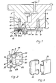
- the pivot bearing consists of a first bearing part 7 attached to the first wing 1 and a second bearing part 8 fastened to the second wing 2. Both are coupled to one another via an axis of rotation 9. At least one of these bearing parts, in particular the first bearing part 7, essentially consists of two elements which can be adjusted relative to one another by means of an adjusting device 10.
- the adjusting device 10 enables a relative movement of the two wings 1 and 2. This allows, for example, their lateral spacing 11 to be changed. The adjustment takes place in or parallel to the common sash level of the closed door.
- the first element 12 of the first bearing part 7 consists of a bearing journal 13 which is rotatably mounted in a bore 14 of the vertical beam 3 and an eccentric 15 17 of the second element 18 of the first bearing part is brought.
- the geometric axis of this intermediate piece is identical to that of the journal 13.
- the eccentric 15 also consists of a pin whose geometric axis according to FIG. 1 is laterally offset from that of the bearing pin 13.
- the adjusting eccentric 15 engages in a first receptacle 19 of the second element 18, its free end projecting outwards. It is deformed into a rivet head 20.
- the first receptacle 19 is a longitudinal slot extending perpendicular to the image plane and thus parallel to the axis of rotation 9. Its width corresponds to the diameter of the pin-shaped eccentric 15, and the length is determined by the movement of the eccentric and the geometric axis of the bearing pin 13.
- the second element 18 can only be displaced in the horizontal direction with respect to the first element 12.
- the first wing can only be aligned in the horizontal direction with respect to the second or vice versa. Vertical alignment is deliberately switched off.
- the first element 12 is held immovably in the vertical slot-shaped first receptacle 19 of the second element 18 by riveting transversely to the wing plane. Between the second Element 18 and the rivet head 20 are connected to a plate spring 23 in the exemplary embodiment. Instead or in addition, a washer can also be used.
- the second bearing part 8 which in the exemplary embodiment is not equipped with an adjusting device, is equipped with at least one, but in the exemplary embodiment with two spaced-in bores 24 and 25 arranged one above the other. Each is pressed into a corresponding bore 26 in the associated wing or wing spar 4. Otherwise, the second bearing part 8 consists essentially of a plate-shaped base body and a centrally arranged bearing eye 27. It is located between two bearing eyes 28 and 29 of the first bearing part 7. In addition, four mounting holes 30 are made on the second bearing part 8.
- the second bearing part 8 is significantly wider than the first bearing part 7. This allows the bores 26 for the drilling pins 24, 25 to be made far enough from a rollover 30 of the second wing 2 .
- the side distance of the bearing pin 13 from the axis of rotation 9 is substantially smaller than the side distance of the axis of rotation 9 from a plane through the drilling pins 24 and 25, and this has a very positive effect with regard to the forces acting.
- the wings to be connected to one another are connected via at least one, but preferably two or three pivot bearings of this type arranged one above the other.
- the bearings are initially fully assembled without the caps 31 and 32. Subsequently, the fastening screws penetrating the openings 21 and 22 are loosened slightly and the fine adjustment of one wing relative to its neighboring wing is now carried out with the aid of the adjusting device 10. Then the loosened screws are tightened again and the cover caps are opened.
Landscapes
- Engineering & Computer Science (AREA)
- Mechanical Engineering (AREA)
- Hinges (AREA)
- Wing Frames And Configurations (AREA)
Priority Applications (1)
| Application Number | Priority Date | Filing Date | Title |
|---|---|---|---|
| AT89105750T ATE69855T1 (de) | 1988-04-30 | 1989-04-01 | Drehlager zur verbindung zweier fluegel eines fensters, einer tuer od. dgl. |
Applications Claiming Priority (2)
| Application Number | Priority Date | Filing Date | Title |
|---|---|---|---|
| DE8805768U | 1988-04-30 | ||
| DE8805768U DE8805768U1 (de) | 1988-04-30 | 1988-04-30 | Drehlager zur Verbindung zweier Flügel eines Fensters, einer Tür od. dgl. |
Publications (3)
| Publication Number | Publication Date |
|---|---|
| EP0340455A1 true EP0340455A1 (fr) | 1989-11-08 |
| EP0340455B1 EP0340455B1 (fr) | 1991-11-27 |
| EP0340455B2 EP0340455B2 (fr) | 1995-04-26 |
Family
ID=6823578
Family Applications (1)
| Application Number | Title | Priority Date | Filing Date |
|---|---|---|---|
| EP89105750A Expired - Lifetime EP0340455B2 (fr) | 1988-04-30 | 1989-04-01 | Pivot pour la connexion de deux battants d'une fenêtre, d'une porte ou similaire |
Country Status (3)
| Country | Link |
|---|---|
| EP (1) | EP0340455B2 (fr) |
| AT (1) | ATE69855T1 (fr) |
| DE (2) | DE8805768U1 (fr) |
Families Citing this family (2)
| Publication number | Priority date | Publication date | Assignee | Title |
|---|---|---|---|---|
| EP0967353A1 (fr) * | 1998-06-26 | 1999-12-29 | Charmag S.A. | Charnière |
| DE20120613U1 (de) | 2001-12-14 | 2002-04-04 | Gretsch-Unitas GmbH Baubeschläge, 71254 Ditzingen | Scharnier |
Citations (4)
| Publication number | Priority date | Publication date | Assignee | Title |
|---|---|---|---|---|
| FR2456820A1 (fr) * | 1979-05-12 | 1980-12-12 | Gretsch Unitas Gmbh | Charniere pour porte notamment pour porte de vehicule |
| EP0098257A2 (fr) * | 1982-06-28 | 1984-01-11 | Ets H. Gerard Et Didier | Ferrures formant articulation pour battants tels que volets, portes ou analogues |
| FR2548722A1 (fr) * | 1983-07-05 | 1985-01-11 | Tordo Charles | Penture a charnieres |
| EP0259618A2 (fr) * | 1986-08-13 | 1988-03-16 | Gebr. Brotschi & Co. AG | Penture de porte et fenêtre, réglable pendant et après le montage |
-
1988
- 1988-04-30 DE DE8805768U patent/DE8805768U1/de not_active Expired
-
1989
- 1989-04-01 AT AT89105750T patent/ATE69855T1/de not_active IP Right Cessation
- 1989-04-01 EP EP89105750A patent/EP0340455B2/fr not_active Expired - Lifetime
- 1989-04-01 DE DE8989105750T patent/DE58900486D1/de not_active Expired - Lifetime
Patent Citations (4)
| Publication number | Priority date | Publication date | Assignee | Title |
|---|---|---|---|---|
| FR2456820A1 (fr) * | 1979-05-12 | 1980-12-12 | Gretsch Unitas Gmbh | Charniere pour porte notamment pour porte de vehicule |
| EP0098257A2 (fr) * | 1982-06-28 | 1984-01-11 | Ets H. Gerard Et Didier | Ferrures formant articulation pour battants tels que volets, portes ou analogues |
| FR2548722A1 (fr) * | 1983-07-05 | 1985-01-11 | Tordo Charles | Penture a charnieres |
| EP0259618A2 (fr) * | 1986-08-13 | 1988-03-16 | Gebr. Brotschi & Co. AG | Penture de porte et fenêtre, réglable pendant et après le montage |
Also Published As
| Publication number | Publication date |
|---|---|
| EP0340455B2 (fr) | 1995-04-26 |
| DE8805768U1 (de) | 1988-06-16 |
| ATE69855T1 (de) | 1991-12-15 |
| EP0340455B1 (fr) | 1991-11-27 |
| DE58900486D1 (de) | 1992-01-09 |
Similar Documents
| Publication | Publication Date | Title |
|---|---|---|
| DE3502175C2 (fr) | ||
| DE4345081A1 (de) | Scharnier für versenkt anzubringende Elektrohaushaltsgeräte | |
| EP0285229B1 (fr) | Charnière réglable, en particulier pour portes | |
| EP3613931B1 (fr) | Module de bande destiné au raccordement mobile par charnière autour d'un axe de charnière d'un battant sur un cadre | |
| DE69000171T2 (de) | Verstellbares und nichtzerlegbares scharnier fuer tueren, fenster oder aehnliche rahmen. | |
| DE3008223A1 (de) | Drehbeschlag fuer ganzglastueren | |
| EP3103948B1 (fr) | Penture pour une porte ou une fenêtre | |
| EP1367203A2 (fr) | Charnière | |
| DE3702957C1 (de) | Scharnierbeschlag fuer Fenster,Tueren o.dgl. | |
| AT402086B (de) | Beschlag für türen, fenster oder dergleichen | |
| EP2754813B1 (fr) | Charnière, notamment pour portes et fenêtres en plastique | |
| EP0118050B1 (fr) | Dispositif de réglage d'une penture de paumelle | |
| WO1990015911A1 (fr) | Charniere | |
| EP0340455B2 (fr) | Pivot pour la connexion de deux battants d'une fenêtre, d'une porte ou similaire | |
| EP2913465A1 (fr) | Dispositif de bande pour portes, fenetres ou similaires | |
| DE9308668U1 (de) | Lagerteil eines Lagers für die wenigstens drehbare Lagerung eines Flügels, eines Fensters, einer Tür o.dgl. | |
| EP1563152B1 (fr) | Charniere | |
| DE19526016B4 (de) | Exzenterverstelleinrichtung für einen Beschlag für Fenster, Türen oder dergleichen | |
| WO2004018815A1 (fr) | Partie de penture pour penture de porte, de fenetre ou similaire | |
| CH649341A5 (en) | Corner joint on a turn-and-tilt window or on a turn-and-tilt door | |
| DE102007025857A1 (de) | Gelenkband für Türen oder Fenster | |
| DE19502362C2 (de) | Positionierungseinrichtung für Beschlagteile | |
| EP0258639B1 (fr) | Palier rotatif avec dispositif de freinage pour un panneau de fenêtre, porte ou similaire | |
| DE9202860U1 (de) | Scharnier für Türflügel von Möbeln mit doppelter Einstellmöglichkeit | |
| EP1979567A1 (fr) | Ensemble charnière permettant une liaison par l'intermédiaire d'une articulation à charnière |
Legal Events
| Date | Code | Title | Description |
|---|---|---|---|
| PUAI | Public reference made under article 153(3) epc to a published international application that has entered the european phase |
Free format text: ORIGINAL CODE: 0009012 |
|
| AK | Designated contracting states |
Kind code of ref document: A1 Designated state(s): AT DE FR GB |
|
| 17P | Request for examination filed |
Effective date: 19900120 |
|
| 17Q | First examination report despatched |
Effective date: 19901204 |
|
| GRAA | (expected) grant |
Free format text: ORIGINAL CODE: 0009210 |
|
| AK | Designated contracting states |
Kind code of ref document: B1 Designated state(s): AT DE FR GB |
|
| REF | Corresponds to: |
Ref document number: 69855 Country of ref document: AT Date of ref document: 19911215 Kind code of ref document: T |
|
| GBT | Gb: translation of ep patent filed (gb section 77(6)(a)/1977) | ||
| REF | Corresponds to: |
Ref document number: 58900486 Country of ref document: DE Date of ref document: 19920109 |
|
| ET | Fr: translation filed | ||
| PLBI | Opposition filed |
Free format text: ORIGINAL CODE: 0009260 |
|
| PLBI | Opposition filed |
Free format text: ORIGINAL CODE: 0009260 |
|
| 26 | Opposition filed |
Opponent name: HOESCH AG, Effective date: 19920817 Opponent name: SIEGENIA-FRANK KG Effective date: 19920813 |
|
| 26 | Opposition filed |
Opponent name: ROTO FRANK AG Effective date: 19920825 Opponent name: HOESCH AG, Effective date: 19920817 Opponent name: SIEGENIA-FRANK KG Effective date: 19920813 |
|
| PLAB | Opposition data, opponent's data or that of the opponent's representative modified |
Free format text: ORIGINAL CODE: 0009299OPPO |
|
| R26 | Opposition filed (corrected) |
Opponent name: SIEGENIA-FRANK KG * 920817 FRIED. KRUPP AG HOESCH- Effective date: 19920813 |
|
| PUAH | Patent maintained in amended form |
Free format text: ORIGINAL CODE: 0009272 |
|
| STAA | Information on the status of an ep patent application or granted ep patent |
Free format text: STATUS: PATENT MAINTAINED AS AMENDED |
|
| 27A | Patent maintained in amended form |
Effective date: 19950426 |
|
| AK | Designated contracting states |
Kind code of ref document: B2 Designated state(s): AT DE FR GB |
|
| ET3 | Fr: translation filed ** decision concerning opposition | ||
| GBTA | Gb: translation of amended ep patent filed (gb section 77(6)(b)/1977) |
Effective date: 19950802 |
|
| REG | Reference to a national code |
Ref country code: GB Ref legal event code: IF02 |
|
| PGFP | Annual fee paid to national office [announced via postgrant information from national office to epo] |
Ref country code: GB Payment date: 20040331 Year of fee payment: 16 |
|
| PGFP | Annual fee paid to national office [announced via postgrant information from national office to epo] |
Ref country code: FR Payment date: 20040415 Year of fee payment: 16 |
|
| PG25 | Lapsed in a contracting state [announced via postgrant information from national office to epo] |
Ref country code: GB Free format text: LAPSE BECAUSE OF NON-PAYMENT OF DUE FEES Effective date: 20050401 |
|
| PGFP | Annual fee paid to national office [announced via postgrant information from national office to epo] |
Ref country code: AT Payment date: 20050414 Year of fee payment: 17 |
|
| PGFP | Annual fee paid to national office [announced via postgrant information from national office to epo] |
Ref country code: DE Payment date: 20050418 Year of fee payment: 17 |
|
| GBPC | Gb: european patent ceased through non-payment of renewal fee |
Effective date: 20050401 |
|
| PG25 | Lapsed in a contracting state [announced via postgrant information from national office to epo] |
Ref country code: FR Free format text: LAPSE BECAUSE OF NON-PAYMENT OF DUE FEES Effective date: 20051230 |
|
| REG | Reference to a national code |
Ref country code: FR Ref legal event code: ST Effective date: 20051230 |
|
| PG25 | Lapsed in a contracting state [announced via postgrant information from national office to epo] |
Ref country code: AT Free format text: LAPSE BECAUSE OF NON-PAYMENT OF DUE FEES Effective date: 20060401 |
|
| PG25 | Lapsed in a contracting state [announced via postgrant information from national office to epo] |
Ref country code: DE Free format text: LAPSE BECAUSE OF NON-PAYMENT OF DUE FEES Effective date: 20061101 |