EP0340462B1 - Four à tambour rotatif pour sécher ou mélanger des matériaux susceptibles de couler ou de ruisseler - Google Patents
Four à tambour rotatif pour sécher ou mélanger des matériaux susceptibles de couler ou de ruisseler Download PDFInfo
- Publication number
- EP0340462B1 EP0340462B1 EP89105913A EP89105913A EP0340462B1 EP 0340462 B1 EP0340462 B1 EP 0340462B1 EP 89105913 A EP89105913 A EP 89105913A EP 89105913 A EP89105913 A EP 89105913A EP 0340462 B1 EP0340462 B1 EP 0340462B1
- Authority
- EP
- European Patent Office
- Prior art keywords
- drum
- wall
- rotating
- flame
- area
- Prior art date
- Legal status (The legal status is an assumption and is not a legal conclusion. Google has not performed a legal analysis and makes no representation as to the accuracy of the status listed.)
- Expired - Lifetime
Links
- 239000000463 material Substances 0.000 title claims abstract description 60
- 238000002156 mixing Methods 0.000 title claims description 8
- 238000001035 drying Methods 0.000 title claims description 4
- 238000009434 installation Methods 0.000 claims description 7
- 239000010426 asphalt Substances 0.000 claims description 4
- 238000002360 preparation method Methods 0.000 claims 1
- 238000011068 loading method Methods 0.000 abstract description 11
- 230000005855 radiation Effects 0.000 abstract description 4
- 230000000694 effects Effects 0.000 abstract description 3
- 230000000717 retained effect Effects 0.000 abstract 1
- 239000000126 substance Substances 0.000 abstract 1
- XLYOFNOQVPJJNP-UHFFFAOYSA-N water Substances O XLYOFNOQVPJJNP-UHFFFAOYSA-N 0.000 description 5
- 238000010438 heat treatment Methods 0.000 description 4
- 239000013590 bulk material Substances 0.000 description 2
- 238000002485 combustion reaction Methods 0.000 description 2
- 238000004519 manufacturing process Methods 0.000 description 2
- 125000006850 spacer group Chemical group 0.000 description 2
- 239000004566 building material Substances 0.000 description 1
- 238000010276 construction Methods 0.000 description 1
- 238000010586 diagram Methods 0.000 description 1
- 230000007613 environmental effect Effects 0.000 description 1
- 239000000446 fuel Substances 0.000 description 1
- 239000002737 fuel gas Substances 0.000 description 1
- 239000007789 gas Substances 0.000 description 1
- 229910052500 inorganic mineral Inorganic materials 0.000 description 1
- 238000009413 insulation Methods 0.000 description 1
- 238000002955 isolation Methods 0.000 description 1
- 238000000034 method Methods 0.000 description 1
- 239000011707 mineral Substances 0.000 description 1
- 230000002093 peripheral effect Effects 0.000 description 1
- 238000004064 recycling Methods 0.000 description 1
- 230000003584 silencer Effects 0.000 description 1
- 239000007787 solid Substances 0.000 description 1
- 230000008646 thermal stress Effects 0.000 description 1
- 238000003466 welding Methods 0.000 description 1
Images

Classifications
-
- F—MECHANICAL ENGINEERING; LIGHTING; HEATING; WEAPONS; BLASTING
- F27—FURNACES; KILNS; OVENS; RETORTS
- F27B—FURNACES, KILNS, OVENS OR RETORTS IN GENERAL; OPEN SINTERING OR LIKE APPARATUS
- F27B7/00—Rotary-drum furnaces, i.e. horizontal or slightly inclined
- F27B7/14—Rotary-drum furnaces, i.e. horizontal or slightly inclined with means for agitating or moving the charge
- F27B7/16—Rotary-drum furnaces, i.e. horizontal or slightly inclined with means for agitating or moving the charge the means being fixed relatively to the drum, e.g. composite means
- F27B7/161—Rotary-drum furnaces, i.e. horizontal or slightly inclined with means for agitating or moving the charge the means being fixed relatively to the drum, e.g. composite means the means comprising projections jutting out from the wall
-
- F—MECHANICAL ENGINEERING; LIGHTING; HEATING; WEAPONS; BLASTING
- F26—DRYING
- F26B—DRYING SOLID MATERIALS OR OBJECTS BY REMOVING LIQUID THEREFROM
- F26B11/00—Machines or apparatus for drying solid materials or objects with movement which is non-progressive
- F26B11/02—Machines or apparatus for drying solid materials or objects with movement which is non-progressive in moving drums or other mainly-closed receptacles
- F26B11/04—Machines or apparatus for drying solid materials or objects with movement which is non-progressive in moving drums or other mainly-closed receptacles rotating about a horizontal or slightly-inclined axis
- F26B11/0463—Machines or apparatus for drying solid materials or objects with movement which is non-progressive in moving drums or other mainly-closed receptacles rotating about a horizontal or slightly-inclined axis having internal elements, e.g. which are being moved or rotated by means other than the rotating drum wall
- F26B11/0477—Machines or apparatus for drying solid materials or objects with movement which is non-progressive in moving drums or other mainly-closed receptacles rotating about a horizontal or slightly-inclined axis having internal elements, e.g. which are being moved or rotated by means other than the rotating drum wall for mixing, stirring or conveying the materials to be dried, e.g. mounted to the wall, rotating with the drum
-
- F—MECHANICAL ENGINEERING; LIGHTING; HEATING; WEAPONS; BLASTING
- F27—FURNACES; KILNS; OVENS; RETORTS
- F27B—FURNACES, KILNS, OVENS OR RETORTS IN GENERAL; OPEN SINTERING OR LIKE APPARATUS
- F27B7/00—Rotary-drum furnaces, i.e. horizontal or slightly inclined
- F27B7/14—Rotary-drum furnaces, i.e. horizontal or slightly inclined with means for agitating or moving the charge
- F27B7/16—Rotary-drum furnaces, i.e. horizontal or slightly inclined with means for agitating or moving the charge the means being fixed relatively to the drum, e.g. composite means
Definitions
- the invention relates to a rotary kiln according to the preamble of patent claim 1.
- the drying drums used on asphalt mixing plants are rotary kilns, in which the aggregates to be processed, in particular minerals, are dried in order to break down the water in them and bring the aggregates to the required production temperature of around 180 - 400 degrees Celsius.
- Such rotary kilns consist of a horizontally or rotatably driven, or inclined towards the discharge Drum. At the discharge end there is a burner, the flame of which is directed coaxially into the flame.
- the material entry into the drum is at the end facing away from the burner.
- trickle internals are attached to the drum wall. These are shovels or cups that take up the material at the bottom of the drum and let it trickle in the zenith area of the rotating drum in order to create a uniform material veil that traverses the drum and thus through the outflow zone of the fuel gases.
- a rotary kiln is known in which the burner is located on the inlet side of the kiln drum.
- the inner wall of the furnace drum is divided into several areas: an inlet area, a transfer area, an intermediate area and a mixing area, behind which the finished bulk material is discharged.
- the inlet area and the transfer area are located itself in the burning area of the burner flame.
- holding fixtures which are trough-shaped in a U-shape and prevent entrained free-flowing material from trickling through the flame.
- the free-flowing material that remains on the underside of the drum is exposed to the direct heat radiation of the burner flame. The same applies to the inner wall of the drum.
- trickle internals are provided on the drum wall, which let the material trickle through the central area of the drum cross section.
- the known device makes it necessary that certain temperature-sensitive feedstocks, for example recycling materials, are introduced through a separate inlet into a central region of the drum behind the flame, from where they are transported to the outlet without being exposed to the direct flame action.
- the burner flame is at the inlet end.
- the length of the rotary kiln is divided into four zones, namely an inlet zone, a transfer and heating zone, an isolation zone and a mixing zone.
- trickle internals are provided on the inner wall of the rotary tube.
- holding fixtures are provided on the inner wall of the rotary tube, which are formed on spacers which protrude radially from the inner wall toward the rotary tube furnace axis and on which L-shaped holding fixtures are fastened.
- the spacers are arranged in a spiral along the inner wall in order to ensure further transport of the embedded bulk material.
- the L-shaped holding fixtures only insufficiently cover the inner wall of the rotary tube.
- the invention has for its object to provide a rotary kiln of the type specified in the preamble of claim 1, in which the thermal peak load of rotary kilns and material to be treated is reduced, and which enables better utilization of the heat generated by the burner while reducing the environmental impact.
- the trickle internals are arranged only in the relatively "cold area" of the loading end of the drum, while the area surrounding the flame has retaining internals.
- holding fixtures is to be understood in such a way that these fixtures take the material in the direction of rotation of the drum, but at the same time hold this material in the peripheral region of the drum. This happens through the pockets that hold the material until just behind the zenith of the drum rotation. After the zenith has been exceeded, the material falls out of the openings in the pockets to reach the plates which overlap in such a way that the material cannot fall into the open interior of the drum.
- the material thus forms a veil of material in the drum area near the wall outside the plates, which protects the drum wall and the pockets against excessive radiant heat.
- the material can move in this area, but because of the overlapping plates do not trickle into the flame or the central area of the drum cross-section.
- the entire combustion chamber is kept free from trickling material; the burnout of the flame is not disturbed. This undisturbed combustion reduces the emission values.
- the material held in the area of the drum near the wall is effectively protected against thermal overloading by radiant heat, this protection also being transferred to the drum wall.
- the dimensioning of the holding fixtures is greater than the maximum possible flame length when the burner is operating at full load.
- an axial heat flow is generated, which is directed towards the loading end of the drum and at the end of the holding fixtures branches into a partial flow leading out of the drum and a further partial flow which runs between the drum wall and holding fixtures to the discharge end, i.e. to the burner.
- the rotary kiln is also particularly suitable for processing bituminous road building materials with the addition of mechanically crushed old asphalt.
- the rotary kiln is not limited to asphalt processing; Rather, it can also be used for the uniform drying and / or mixing of other free-flowing materials Materials are used.
- the material can be transported in the longitudinal direction of the drum either by tilting the drum or in that the internals provided in the drum are inclined in such a way that they bring about material conveyance in the longitudinal direction.
- the pocket walls are attached to the drum wall only at one end, while the other end protrudes freely. Thereby thermal changes in length of the pocket walls are possible without hindrance.
- Each pocket wall is loosely supported at its free end with at least one arm on the adjacent pocket wall, the arms leaving the pocket opening free. In this way, a high mechanical strength of the pockets is achieved while at the same time allowing thermal expansion.
- Claim 3 relates to a preferred attachment of the plates to the pocket walls.
- the plates keep the plates at the required radial distance from the pocket openings, so that the material can fall down in the sloping region of the drum circumference between the pocket walls and the plates.
- a prechamber is provided on the burner, the wall of which protects the foot region of the flame.
- This antechamber is open at the bottom so that material that gets into the antechamber can fall out.
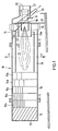
- FIG. 1 shows a schematic longitudinal section of the rotary kiln.
- This rotary kiln has a cylindrical drum 10 which is mounted in rotary bearings 11 and is driven by a rotary drive (not shown) about its longitudinal axis.
- the drum 10 is inclined, the loading end 12 being higher than the discharge end 13.
- trickle internals 15a to 15e are provided, which are fastened to the drum wall 16 and are designed as radially projecting sheets or as a cup.
- the trickle internals take the material from the lower area of the drum rotation in order to let this material trickle into the interior of the drum in the upper area of the drum rotation.
- the trickle internals 15a to 15e extend approximately to the middle of the drum length. They differ in the circumferential spacing of the sheets or cups, which increases towards the middle of the drum length, that is to say is less in the trickle internals 15a than in the trickle internals 15e.
- the burner 18 is fastened to a stationary holder 17, which is connected to a fuel line 19 and sucks in air via a suction opening 20.
- the suction opening 20 is surrounded by a silencer 21.
- the burner 18 generates a flame 22 which is directed coaxially to the drum axis into the drum 10.
- the foot region of the flame 22 is surrounded by a prechamber wall 23 which protects the flame against external influences and which on lower end 23a is open so that foreign objects can fall out.
- a lifting bucket 24 is attached to the drum wall 10 around the prechamber 23. This lifting bucket 24 is used to lift the material over a stationary funnel 25 and to drop it into the funnel 25.
- a slide 26 leads from the hopper 25 to the material outlet.
- the flame area 27 is the area of the drum 10 that can receive the flame 22. This does not mean that the flame 22 must extend the full length of the flame area 27.
- the flame area 27 is surrounded by the holding fixtures 28 which are fastened to the inside of the drum wall 16. These holding fixtures 28 extend from the inner trickle fixtures 15e to the discharge end 13.
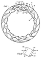
- the construction of the holding fixtures 28 results from the FIGS. 2 and 3.
- the holding fixtures 28 have numerous pockets 29 which are each delimited by the drum wall 16 and by a pocket wall 30.
- the pocket wall 30 is fastened at one end 30a to the drum wall 16, for example by welding, while the other end 30b projects freely in the manner of a cantilever.
- the pocket wall 30 is inclined in the direction of rotation of the drum, so that there is an opening 31 between the free end 30b of each pocket wall and the leading pocket wall. This opening 31 is bridged by two arms 32 which protrude from the end 30b and protrude in the vicinity of the leading pocket wall 30, but without being connected to this leading pocket wall.
- the end 30a of the pocket wall 30 is divided by an expansion slot 33 in the longitudinal direction of the drum.
- a plate 35 extending in the longitudinal direction of the drum is fastened to each pocket wall 30 via radially inwardly directed webs 34.
- the plates 35 form the inner boundaries of the holding fixtures 28. They are oriented approximately tangentially to the drum, and their ends overlap in every rotational position of the drum when the plates are projected onto a horizontal plane.
- FIG. 2 shows the material to be treated, which is located in the lower region of the drum in the pockets 29 and falls out of the respective opening 31 in the vicinity of the zenith of the drum rotation.
- the material then gets onto the outer sides of the plates 35 and is prevented by the overlapping of the plates from falling into the central region of the drum cross section and forming a trickling veil passing through the flame 22.
- the plates 35 hold the material in the region of the drum near the wall, where it falls in the sloping part of the drum circumference (right half of FIG. 2) between the pocket walls 30 and the plates 35.
- the material is again taken up by the pockets 29 through the openings 31. It can be seen that the plates 35 and the free-flowing material shield the drum wall 16 over the entire area of the drum circumference against the heat radiation of the flame 22.
- FIG. 4a shows the heat flow 40, which is greatest in the flame region 27 enclosed by the holding installations 28 and flows in the direction of the loading end 12.
- the heat flow 40 branches into a partial flow 40a flowing to the loading end 12 and a partial flow 40b flowing through the holding fixtures 28 in the longitudinal direction in cocurrent with the material to be treated.
- This partial flow 40b is combined with the heat flow 40 again after leaving the burner end of the holding fixtures 28.
- the partial flow 40b partially sucks in the water vapor generated in the area of the trickle internals from the loading end 12 and carries it along into the flame area 27.
- the solid curve 43 in FIG. 4c shows the course of the material flow density in the known rotary kilns, and in comparison the curve 42 shows the course of the material flow density in the described rotary kiln.
- the material flow density is the measure of the material falling through the heat flow.
- the material flow density in the area of the loading end of the rotary kiln is disproportionately high, in order to then decrease very sharply until the start of the holding internals.
- the material flow density is zero in the entire flame area - due to the holding fixtures - i.e. no material falls through the flame area.
- the thermal drum load is plotted against the drum length, curve 44 representing the course of the drum load in known rotary furnaces and, by comparison, curve 45 representing the drum load in the rotary kiln according to the invention. It can be seen that the thermal drum loading of curve 45 is consistently below that of curve 44, which is due to the effect of drum internals 28. In particular, the sucked-in water vapor flow 41 (FIG. 4a) also has an effect with regard to a reduction in the thermal drum load.
Landscapes
- Engineering & Computer Science (AREA)
- Mechanical Engineering (AREA)
- General Engineering & Computer Science (AREA)
- Muffle Furnaces And Rotary Kilns (AREA)
- Drying Of Solid Materials (AREA)
Claims (4)
- Four rotatif pour sécher et/ou mélanger un matériau susceptible de couler, en particulier pour la préparation de l'asphalte, comportant
un tambour (10) entraîné en rotation,
un brûleur (18) qui pénètre dans l'extrémité de sortie du tambour (10),
des garnitures d'écoulement (15a-15e) prévues sur la paroi du tambour (16), qui se trouvent dans la zone de l'extrémité d'entrée (12) du tambour (10) et qui opèrent un écoulement du matériau à travers la zone médiane de la section du tambour, et
des garnitures de maintien (28) prévues dans la zone entourant la flamme du brûleur (28),
four caractérisé
par le fait que les garnitures de maintien (28) présentent des poches (29) dont les ouvertures (31) sont, en direction de l'intérieur du tambour, recouvertes par des plaques (35) disposées à distance, étant précisé que les plaques (35), en projection sur le plan horizontal, se recouvrent mutuellement de façon telle que les garnitures de maintien retiennent le matériau au voisinage de la paroi du tambour même après dépassement du point haut de la rotation du tambour. - Four rotatif selon la revendication 1, caractérisé par le fait que les poches 29 sont limitées vers l'extérieur par la paroi du tambour (16) et vers l'intérieur par une paroi de poche (30), la paroi de poche (30) étant, par une extrémité (30a), fixée à la paroi du tambour (16) et pouvant, par l'autre extrémité (30b), s'appuyer sur la paroi de poche voisine par au moins un bras (32).
- Four rotatif selon la revendication 2, caractérisé par le fait que les plaques (35) sont fixées aux parois de poches (30) par des goussets (34).
- Four rotatif selon l'une des revendications 1 à 3, caractérisé par le fait que la sortie du brûleur est contenue dans une préchambre (23) fixe en position qui s'étend dans la zone des garnitures de maintien (28) et dont la paroi est ouverte vers le bas.
Priority Applications (1)
| Application Number | Priority Date | Filing Date | Title |
|---|---|---|---|
| AT89105913T ATE93048T1 (de) | 1988-05-04 | 1989-04-05 | Drehofen zum trocknen und/oder mischen von rieselfaehigem material. |
Applications Claiming Priority (2)
| Application Number | Priority Date | Filing Date | Title |
|---|---|---|---|
| DE3815104A DE3815104A1 (de) | 1988-05-04 | 1988-05-04 | Drehofen zum trocknen und/oder mischen von rieselfaehigem material |
| DE3815104 | 1988-05-04 |
Publications (2)
| Publication Number | Publication Date |
|---|---|
| EP0340462A1 EP0340462A1 (fr) | 1989-11-08 |
| EP0340462B1 true EP0340462B1 (fr) | 1993-08-11 |
Family
ID=6353560
Family Applications (1)
| Application Number | Title | Priority Date | Filing Date |
|---|---|---|---|
| EP89105913A Expired - Lifetime EP0340462B1 (fr) | 1988-05-04 | 1989-04-05 | Four à tambour rotatif pour sécher ou mélanger des matériaux susceptibles de couler ou de ruisseler |
Country Status (3)
| Country | Link |
|---|---|
| EP (1) | EP0340462B1 (fr) |
| AT (1) | ATE93048T1 (fr) |
| DE (2) | DE3815104A1 (fr) |
Families Citing this family (12)
| Publication number | Priority date | Publication date | Assignee | Title |
|---|---|---|---|---|
| US5080581A (en) * | 1991-04-10 | 1992-01-14 | Combustion Design Corporation | Method and apparatus for drying waste materials |
| DE4243264C2 (de) * | 1992-12-19 | 1997-03-20 | Deutag Ag | Verfahren zum Betreiben eines Drehrohrofens zum Trocknen und Mischen von rieselfähigem Material |
| DE9319897U1 (de) * | 1993-05-18 | 1994-03-31 | U. Ammann Maschinenfabrik Ag, Langenthal | Vorrichtung zum Trocknen und/oder Erwärmen von rieselfähigem Material |
| US5480226A (en) * | 1994-05-09 | 1996-01-02 | Astec Industries, Inc. | Rotary drum dryer having aggregate cooled shielding flights and method for the utilization thereof |
| US5772317A (en) * | 1996-08-27 | 1998-06-30 | Gencor Industries, Inc. | Counterflow drum mixer for making asphaltic concrete and methods of operation |
| RU2164328C2 (ru) * | 1999-04-09 | 2001-03-20 | Открытое акционерное общество "Себряковцемент" | Встроенный теплообменник вращающейся печи |
| DE10240249B3 (de) | 2002-08-31 | 2004-02-26 | Enerco Bv | Anlage zum Trocknen und Aufbereiten von rieselfähigem mineralischem Gut |
| DE102004036109B4 (de) * | 2004-07-08 | 2006-08-03 | BLüCHER GMBH | Drehrohr für die Aktivkohleherstellung und seine Verwendung |
| ATE537300T1 (de) | 2009-07-09 | 2011-12-15 | Ammann Italy S P A | Drehtrockner für anlagen zur herstellung von bituminösem mischgut unter verwendung von wiederverwendeten materialien |
| ES2377104T3 (es) | 2009-07-09 | 2012-03-22 | Ammann Italy S.P.A. | Cilindro de secado del tipo usado en plantas para la producción de macadanes bituminosos |
| GB2506440A (en) * | 2012-10-01 | 2014-04-02 | Ian Brian Lewis | Apparatus for drying particulate material |
| DE102021210662B4 (de) | 2021-09-24 | 2025-07-10 | Benninghoven Zweigniederlassung Der Wirtgen Mineral Technologies Gmbh | Vorrichtung und Verfahren zum Trocknen von Material sowie Asphaltmischanlage mit einer derartigen Vorrichtung |
Family Cites Families (8)
| Publication number | Priority date | Publication date | Assignee | Title |
|---|---|---|---|---|
| FR1116508A (fr) * | 1954-12-03 | 1956-05-08 | Cie De Fives Lille | Perfectionnements aux fours à chaux et à ciment |
| BE858730A (fr) * | 1977-09-15 | 1978-01-02 | Obourg Sa Ciments | Procede et dispositif pour augmenter les echanges calorifiques entre matiere solide et gaz, dans un four rotatif a ciment |
| US4189300A (en) * | 1978-08-28 | 1980-02-19 | Mechtron International Corporation | Rotating drum dryer apparatus |
| FR2441682A1 (fr) * | 1978-11-17 | 1980-06-13 | Creusot Loire | Dispositif pour la preparation de produits enrobes bitumineux pour revetements routiers |
| DE2914965A1 (de) * | 1979-04-12 | 1980-10-23 | Bayer Ag | Drehrohr |
| DE2949479A1 (de) * | 1979-12-08 | 1981-06-11 | Metallgesellschaft Ag, 6000 Frankfurt | Verfahren zum trocknen und kalzinieren von schuettguetern |
| FR2473578B1 (fr) * | 1980-01-11 | 1986-03-21 | Creusot Loire | |
| DE3110380C2 (de) * | 1981-03-17 | 1984-02-16 | ATS Asphalttechnik und Straßenbaugeräte GmbH & Co KG, 6236 Eschborn | Verfahren zur Aufbereitung von Asphaltmischgut unter Wiederverwendung alten Asphaltmaterials sowie eine Vorrichtung zur Durchführung des Verfahrens |
-
1988
- 1988-05-04 DE DE3815104A patent/DE3815104A1/de not_active Withdrawn
-
1989
- 1989-04-05 DE DE8989105913T patent/DE58905214D1/de not_active Expired - Fee Related
- 1989-04-05 AT AT89105913T patent/ATE93048T1/de not_active IP Right Cessation
- 1989-04-05 EP EP89105913A patent/EP0340462B1/fr not_active Expired - Lifetime
Also Published As
| Publication number | Publication date |
|---|---|
| DE3815104A1 (de) | 1989-11-09 |
| ATE93048T1 (de) | 1993-08-15 |
| EP0340462A1 (fr) | 1989-11-08 |
| DE58905214D1 (de) | 1993-09-16 |
Similar Documents
| Publication | Publication Date | Title |
|---|---|---|
| DE69218962T2 (de) | Drehtrommeltrockner mit inneren schaufeln | |
| EP0340462B1 (fr) | Four à tambour rotatif pour sécher ou mélanger des matériaux susceptibles de couler ou de ruisseler | |
| DE1961531U (de) | Ofen zur thermischen behandlung von brennstoffbriketts oder klassierter kohle. | |
| DE2433676C3 (de) | Drehtrommelofen zur Veraschung von Abfällen | |
| DE2906049C2 (de) | Mischer für bituminöse Fahrbahnbeschichtungsmassen | |
| DE3520819C2 (de) | Verfahren zur thermischen Behandlung von mit Schadstoffen belasteten Massen sowie Anlage zur Durchführung eines solchen Verfahrens | |
| DE1919137A1 (de) | Verfahren und Vorrichtung zum Erhitzen von brennbare Fremdstoffe mitfuehrendem Gut und Verbrennen der Fremdstoffe | |
| DE4243264C2 (de) | Verfahren zum Betreiben eines Drehrohrofens zum Trocknen und Mischen von rieselfähigem Material | |
| DE3030305A1 (de) | Verfahren und ofen zum verbrennen von festem brennstoff | |
| DE19935597C2 (de) | Feuerung | |
| DE69001126T2 (de) | Vorrichtung zur aufbereitung von bituminoesem mischgut mit einer gleichstrom- und einer gegenstromtrommel und entsprechendes verfahren. | |
| CH270587A (de) | Verfahren zum Regenerieren von körnigem Material und Einrichtung zur Ausübung dieses Verfahrens. | |
| DE3110380C2 (de) | Verfahren zur Aufbereitung von Asphaltmischgut unter Wiederverwendung alten Asphaltmaterials sowie eine Vorrichtung zur Durchführung des Verfahrens | |
| DE2612198C3 (de) | Wurfbeschicker zum Eintragen von Verbrennungsgut in einen Verbrennungsofen | |
| DE1526103B1 (de) | Drehrohrofen zur kontinuierlichen Veraschung von Abfaellen | |
| DE2444641B2 (de) | Trocknungs- und verbrennungsofen fuer feststoffhaltige materialien, wie schlaemme und dergleichen | |
| DE60122976T2 (de) | Entladeschnecke für einen beweglichen Herd | |
| DE3701455C2 (fr) | ||
| DE3924074C2 (fr) | ||
| DE3934581C2 (de) | Verfahren und Vorrichtung zum Verbrennen von Abfallstoffen insbesondere unterschiedlichster Zusammensetzung | |
| DE3824615C2 (fr) | ||
| DE2603206C3 (de) | Feuerungseinrichtung | |
| DE916944C (de) | Verfahren und Vorrichtung zur Schwelung von festem Kohlenstoffhaltigem Material | |
| DE1526103C (de) | Drehrohrofen zur kontinuierlichen Veraschung von Abfallen | |
| DE1171326B (de) | Vorrichtung zur Herstellung von Gips |
Legal Events
| Date | Code | Title | Description |
|---|---|---|---|
| PUAI | Public reference made under article 153(3) epc to a published international application that has entered the european phase |
Free format text: ORIGINAL CODE: 0009012 |
|
| AK | Designated contracting states |
Kind code of ref document: A1 Designated state(s): AT BE CH DE FR LI NL |
|
| 17P | Request for examination filed |
Effective date: 19900328 |
|
| 17Q | First examination report despatched |
Effective date: 19910708 |
|
| RAP1 | Party data changed (applicant data changed or rights of an application transferred) |
Owner name: DEUTAG ASPHALTTECHNIK GMBH |
|
| GRAA | (expected) grant |
Free format text: ORIGINAL CODE: 0009210 |
|
| AK | Designated contracting states |
Kind code of ref document: B1 Designated state(s): AT BE CH DE FR LI NL |
|
| REF | Corresponds to: |
Ref document number: 93048 Country of ref document: AT Date of ref document: 19930815 Kind code of ref document: T |
|
| REF | Corresponds to: |
Ref document number: 58905214 Country of ref document: DE Date of ref document: 19930916 |
|
| ET | Fr: translation filed | ||
| PLBE | No opposition filed within time limit |
Free format text: ORIGINAL CODE: 0009261 |
|
| STAA | Information on the status of an ep patent application or granted ep patent |
Free format text: STATUS: NO OPPOSITION FILED WITHIN TIME LIMIT |
|
| 26N | No opposition filed | ||
| PGFP | Annual fee paid to national office [announced via postgrant information from national office to epo] |
Ref country code: FR Payment date: 19970516 Year of fee payment: 9 |
|
| PGFP | Annual fee paid to national office [announced via postgrant information from national office to epo] |
Ref country code: BE Payment date: 19970522 Year of fee payment: 9 |
|
| PGFP | Annual fee paid to national office [announced via postgrant information from national office to epo] |
Ref country code: CH Payment date: 19970523 Year of fee payment: 9 |
|
| PG25 | Lapsed in a contracting state [announced via postgrant information from national office to epo] |
Ref country code: LI Free format text: LAPSE BECAUSE OF NON-PAYMENT OF DUE FEES Effective date: 19980430 Ref country code: FR Free format text: THE PATENT HAS BEEN ANNULLED BY A DECISION OF A NATIONAL AUTHORITY Effective date: 19980430 Ref country code: CH Free format text: LAPSE BECAUSE OF NON-PAYMENT OF DUE FEES Effective date: 19980430 Ref country code: BE Free format text: LAPSE BECAUSE OF NON-PAYMENT OF DUE FEES Effective date: 19980430 |
|
| NLS | Nl: assignments of ep-patents |
Owner name: BENNINGHOVEN GMBH & CO. KG;DEUTAG AG;DEUTAG GMBH & |
|
| BERE | Be: lapsed |
Owner name: DEUTAG ASPHALTTECHNIK G.M.B.H. Effective date: 19980430 |
|
| REG | Reference to a national code |
Ref country code: CH Ref legal event code: PL |
|
| REG | Reference to a national code |
Ref country code: FR Ref legal event code: ST |
|
| PGFP | Annual fee paid to national office [announced via postgrant information from national office to epo] |
Ref country code: NL Payment date: 19990422 Year of fee payment: 11 Ref country code: AT Payment date: 19990422 Year of fee payment: 11 |
|
| PG25 | Lapsed in a contracting state [announced via postgrant information from national office to epo] |
Ref country code: AT Free format text: LAPSE BECAUSE OF NON-PAYMENT OF DUE FEES Effective date: 20000405 |
|
| PG25 | Lapsed in a contracting state [announced via postgrant information from national office to epo] |
Ref country code: NL Free format text: LAPSE BECAUSE OF NON-PAYMENT OF DUE FEES Effective date: 20001101 |
|
| NLV4 | Nl: lapsed or anulled due to non-payment of the annual fee |
Effective date: 20001101 |
|
| PGFP | Annual fee paid to national office [announced via postgrant information from national office to epo] |
Ref country code: DE Payment date: 20010627 Year of fee payment: 13 |
|
| PG25 | Lapsed in a contracting state [announced via postgrant information from national office to epo] |
Ref country code: DE Free format text: LAPSE BECAUSE OF NON-PAYMENT OF DUE FEES Effective date: 20021101 |