EP0340539B1 - Machine combinée pour le travail agricole et procédé pour son relevage - Google Patents
Machine combinée pour le travail agricole et procédé pour son relevage Download PDFInfo
- Publication number
- EP0340539B1 EP0340539B1 EP89107056A EP89107056A EP0340539B1 EP 0340539 B1 EP0340539 B1 EP 0340539B1 EP 89107056 A EP89107056 A EP 89107056A EP 89107056 A EP89107056 A EP 89107056A EP 0340539 B1 EP0340539 B1 EP 0340539B1
- Authority
- EP
- European Patent Office
- Prior art keywords
- drill
- cultivating machine
- follower roller
- ground cultivating
- frame
- Prior art date
- Legal status (The legal status is an assumption and is not a legal conclusion. Google has not performed a legal analysis and makes no representation as to the accuracy of the status listed.)
- Expired - Lifetime
Links
Images


Classifications
-
- A—HUMAN NECESSITIES
- A01—AGRICULTURE; FORESTRY; ANIMAL HUSBANDRY; HUNTING; TRAPPING; FISHING
- A01C—PLANTING; SOWING; FERTILISING
- A01C15/00—Fertiliser distributors
- A01C15/005—Undercarriages, tanks, hoppers, stirrers specially adapted for seeders or fertiliser distributors
-
- A—HUMAN NECESSITIES
- A01—AGRICULTURE; FORESTRY; ANIMAL HUSBANDRY; HUNTING; TRAPPING; FISHING
- A01B—SOIL WORKING IN AGRICULTURE OR FORESTRY; PARTS, DETAILS, OR ACCESSORIES OF AGRICULTURAL MACHINES OR IMPLEMENTS, IN GENERAL
- A01B49/00—Combined machines
- A01B49/04—Combinations of soil-working tools with non-soil-working tools, e.g. planting tools
- A01B49/06—Combinations of soil-working tools with non-soil-working tools, e.g. planting tools for sowing or fertilising
- A01B49/065—Combinations of soil-working tools with non-soil-working tools, e.g. planting tools for sowing or fertilising the soil-working tools being actively driven
-
- A—HUMAN NECESSITIES
- A01—AGRICULTURE; FORESTRY; ANIMAL HUSBANDRY; HUNTING; TRAPPING; FISHING
- A01C—PLANTING; SOWING; FERTILISING
- A01C7/00—Sowing
- A01C7/20—Parts of seeders for conducting and depositing seed
- A01C7/208—Chassis; Coupling means to a tractor or the like; Lifting means; Side markers
Definitions
- the invention relates to a method for excavating an agricultural order combination and an agricultural order combination on which the method is carried out according to the preamble of claims 1 and 2 respectively.
- the seed drill is supported on the packer roller.
- an upper coupling element which is designed as a hydraulic cylinder, the seed drill is articulated on the headstock, which is arranged on the tillage machine for connecting the upper link of the three-point linkage of a tractor.
- the weight of the seed drill rests on the frame of the packer roller during operation.
- the packer roller in turn is connected to the tillage machine by means of support arms in such a way that the tillage machine can be lifted by a certain stroke without first lifting the packer roller with the seed drill.
- the invention has for its object to provide a method for lifting an order combination according to the preamble of claim 1 and an order combination itself for performing the method, in which the overall construction of the combination overall structurally simple and with less heavy components can be realized.
- the gear housing on the tillage machine, on which the packer roller with its support arms sits when lifting can be made less strong.
- the arms of the packer roller can be made less strong, since they only have to bear the weight of the packer roller itself when it is being lifted.
- a flexible or chain-shaped or telescopic lifting element is arranged as a connecting element for lifting the seed drill between the headstock of the tillage machine and the seed drill, which is dimensioned so that it comes to tension when lifting the tillage machine and thereby Applies lifting force to the seed drill before the packer roller is forcibly lifted.
- the support arms can be coupled to the drill in an adjustable manner.
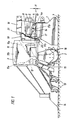
- the agricultural order combination according to Figures 1 and 2 consists of the PTO-driven tillage machine 1, which is a rotary harrow in the illustrated embodiment, and one arranged behind the tillage machine 1 trailing roller 2 and the seed drill 3 saddled on the trailing roller 2.
- the present description means that the weight of the seed drill is absorbed by the packer roller or the soil tillage implement, so the seed drill does not have its own undercarriage.
- the coulters 13 engage behind the packer roller 2 in the ground and that harrow elements 14 still act behind the coulters.
- the trailing roller 2 is coupled to the tillage machine 1 via the support arms 4.
- the joint 4a which enables an articulated articulation of the free end of the support arms 4 pointing to the tillage machine 1, which is symmetrical to the central axis of the order combination as viewed in the direction of travel, on the gearbox of the tillage machine.
- On the frame of the tillage machine 1 there are further adjustment elements 5, which, viewed in the direction of travel, lie behind the joints 4a of the support arms 4.
- the depth of engagement of the tillage tools 6 of the tillage machine in the soil 7 can be adjusted via these adjustment elements 5, which act as a stop for the support arms 4.
- the adjusting elements 5 consist of the perforated elements 8 and the pin 10 which can be inserted into the holes 9, against which the support arms 4 of the trailing roller 2 come to rest. by inserting the bolt 10 into the different holes 9 of the hole element, as mentioned, the working depth of the tillage tools 6 can be adjusted.
- the saddled seed drill 3 has a storage container 11 which lies above the packer roller.
- the storage container 11 of the seed drill has a tapering bottom, which is indicated by the dashed lines 11a, and two side walls 11b which are drawn deeper than the lower end of the bottom 11a. With these side walls 11b, the storage container and thus the seed drill sit on the top of the frame 16 of the packer roller 2 during operation. However, there is no positive connection between the frame 16 and the side walls 11b. Rather, the storage container rests on this frame 16 merely because of the weight of the seed drill.
- a frame support 20 runs between the two side walls of the drill, which rises from the side walls to the center, at which point an upper link 19 connects the headstock 18 to the frame support 20.
- two articulation points 17a are also attached, which are arranged symmetrically to the center of the vehicle to the right and left of the frame support 18. Only one articulation point can be seen in the drawings.
- Support arms 17, which connect the articulation points 17a to the support frame 20 in an articulated manner, act on these articulation points 17a. Between the free ends of the support arms 17, a cross strut, not shown in the drawings, runs approximately along the axis designated 17b in the drawing.
- this cross strut is the lifting element, in the drawn Exemplary embodiment in the form of a chain 21, articulated at one end, while the other end is connected to the trestle 18 at approximately the height at which the upper link of the three-point linkage of a tractor engages.
- This lifting element 21 is dimensioned such that it comes under tension when it is lifted (see FIG. 2) and thus lifts the storage container 11 and thus also the seed drill from its seat on the packer roller, even before the support arm 4 of the packer roller on the surface 1a of the transmission housing fully seated, as shown in Figure 2. Decoupling of the application of force to the packer roller thus takes place, so that the weight of the seed drill is introduced into the trestle 18 solely via the lifting element 21.
- the lifting element is loose in the working position according to FIG. 1.
- This stroke designated H in FIG. 1, is dimensioned in height such that it is sufficient to enable the tillage machine 1 to evade by lifting it over stones.
- the tillage machine can thus be moved freely by the lifting height H relative to the seed drill and the packer roller, which considerably reduces the risk of damage to the tools of the tillage machine.
- the tillage machine 1 is raised. Even before the packer roller is seated on the surface 1a of the frame of the tillage machine, the lifting element 21 comes under tension and thus lifts the seed drill against the packer roller (see FIG. 2).
- the support arm 4 of the packer roller comes to rest on the surface 1a of the frame and is thereby prevented from falling further relative to the tillage machine.
- the upper frame of the tillage machine therefore only needs to take up the weight of the packer roller, but not the weight of the seed drill. The operations are carried out in the reverse order when they are placed.
- the support arms 17 have several bores, not shown, per change in length, so that seed drills and tillage machines of different types can be coupled to one another.
- Both a single lifting element in the form of a chain 21 or also in the form of another telescopic or flexible element which acts in the middle of the cross strut or in the center of the frame of the seed drill can be provided, but it is also possible to provide two such lifting elements, which engage with their lower ends in the area of the free ends of the support arms 17 pointing towards the drill or directly on other frame parts of the drill, while they converge with their upper ends and on the headstock 18, the upper end of which lies in the central axis of the order combination, are put together.
- the order combination also consists of a PTO-driven tillage implement 1, one trailing roller 22 arranged behind the tillage machine 1 and a seed drill 3 saddled on the trailing roller 22.
- the trailing roller 22 is via the support arms 23 which, in contrast to the exemplary embodiment in FIGS. 1 and 2, are arranged laterally on the outside next to the trailing roller 22 on both sides, articulated to the tillage machine 1.
- On the frame of the tillage machine there are in turn setting elements 24 corresponding to the setting elements 5 described in FIG.
- the seed drill is supported with lower support elements 25 on both sides on the support arms 23 of the packer roller or follower roller.
- Elongated holes serve as supports, into which bolts correspondingly arranged on the support arms 23 engage. These elongated holes 25a allow the drill to move vertically relative to the packer roller, so that when the lifting element 21 is pulled under tension as described in FIG is raised in the raised state on the frame of the tillage machine. In this embodiment, the seed drill is guided by the support elements 25 against lateral displacements even in the raised state on the support arms 23.
Landscapes
- Life Sciences & Earth Sciences (AREA)
- Soil Sciences (AREA)
- Environmental Sciences (AREA)
- Engineering & Computer Science (AREA)
- Mechanical Engineering (AREA)
- Soil Working Implements (AREA)
- Agricultural Machines (AREA)
- Making Paper Articles (AREA)
- Pyrane Compounds (AREA)
- Graft Or Block Polymers (AREA)
Claims (9)
Priority Applications (1)
| Application Number | Priority Date | Filing Date | Title |
|---|---|---|---|
| AT89107056T ATE64262T1 (de) | 1988-04-27 | 1989-04-19 | Landwirtschaftliche bestellkombination und verfahren zu ihrem ausheben. |
Applications Claiming Priority (2)
| Application Number | Priority Date | Filing Date | Title |
|---|---|---|---|
| DE3814149A DE3814149A1 (de) | 1988-04-27 | 1988-04-27 | Landwirtschaftliche bestellkombination |
| DE3814149 | 1988-04-27 |
Publications (3)
| Publication Number | Publication Date |
|---|---|
| EP0340539A2 EP0340539A2 (fr) | 1989-11-08 |
| EP0340539A3 EP0340539A3 (en) | 1990-04-04 |
| EP0340539B1 true EP0340539B1 (fr) | 1991-06-12 |
Family
ID=6352956
Family Applications (1)
| Application Number | Title | Priority Date | Filing Date |
|---|---|---|---|
| EP89107056A Expired - Lifetime EP0340539B1 (fr) | 1988-04-27 | 1989-04-19 | Machine combinée pour le travail agricole et procédé pour son relevage |
Country Status (3)
| Country | Link |
|---|---|
| EP (1) | EP0340539B1 (fr) |
| AT (1) | ATE64262T1 (fr) |
| DE (4) | DE8816541U1 (fr) |
Cited By (1)
| Publication number | Priority date | Publication date | Assignee | Title |
|---|---|---|---|---|
| CN108848709A (zh) * | 2018-06-07 | 2018-11-23 | 明光市涧溪镇桃花溪家庭农场 | 一种高效种植小麦装置 |
Families Citing this family (5)
| Publication number | Priority date | Publication date | Assignee | Title |
|---|---|---|---|---|
| FR2707831B1 (fr) * | 1993-07-19 | 1995-09-29 | Kuhn Sa | Machine combinée de travail du sol et de semis dont le semoir est mieux tenu durant le transport. |
| DE4417964B4 (de) * | 1994-05-21 | 2004-08-26 | Lemken Gmbh & Co. Kg | Landwirtschaftliche Maschine |
| NL1003921C2 (nl) * | 1996-08-30 | 1998-03-04 | Maasland Nv | Machinecombinatie. |
| CN108476629A (zh) * | 2018-03-20 | 2018-09-04 | 张鑫 | 一种盐碱地园林土壤改良施肥装置 |
| CN110121953B (zh) * | 2019-06-15 | 2022-06-28 | 甘肃农业大学 | 一种免耕一膜两年用小麦穴播机 |
Family Cites Families (10)
| Publication number | Priority date | Publication date | Assignee | Title |
|---|---|---|---|---|
| FR999134A (fr) * | 1945-11-14 | 1952-01-28 | Instrument aratoire permettant successivement, dans un seul parcours, de labourer, seer et éventuellement herser | |
| DE1836772U (de) * | 1959-10-17 | 1961-08-31 | Lemken Kg Pflugfab | Vorrichtung zur aufrechterhaltung einer betriebsnotwendigen druckbeanspruchung im oberen lenker von mittels viergelenken angebauten bodenbearbeitungsgeraeten. |
| NL6601808A (fr) * | 1966-02-14 | 1967-08-15 | ||
| US4241674A (en) * | 1979-01-11 | 1980-12-30 | Mellinger Manufacturing Co., Inc. | Sub-soil planter |
| AT391050B (de) * | 1982-08-31 | 1990-08-10 | Rau Gmbh Maschf | Kombinationsgeraet zur landwirtschaftlichen bodenbearbeitung |
| DE8513763U1 (de) * | 1985-05-09 | 1987-05-07 | Amazonen-Werke H. Dreyer Gmbh & Co Kg, 4507 Hasbergen | Geschlossene Gerätekombination für die Landwirtschaft |
| DE3543691A1 (de) * | 1985-09-21 | 1987-06-19 | Amazonen Werke Dreyer H | Geschlossene geraetekombination |
| DE8707011U1 (de) * | 1986-05-30 | 1987-07-09 | Amazonen-Werke H. Dreyer Gmbh & Co Kg, 4507 Hasbergen | Sämaschine |
| NL8602430A (nl) * | 1986-09-26 | 1988-04-18 | Lely Nv C Van Der | Grondbewerkingsmachine. |
| DE3738134A1 (de) * | 1987-10-09 | 1989-06-01 | Amazonen Werke Dreyer H | Landwirtschaftliche bestellkombination |
-
1988
- 1988-04-27 DE DE8816541U patent/DE8816541U1/de not_active Expired
- 1988-04-27 DE DE3814149A patent/DE3814149A1/de not_active Withdrawn
-
1989
- 1989-04-19 DE DE8989107056T patent/DE58900144D1/de not_active Expired - Lifetime
- 1989-04-19 EP EP89107056A patent/EP0340539B1/fr not_active Expired - Lifetime
- 1989-04-19 AT AT89107056T patent/ATE64262T1/de not_active IP Right Cessation
- 1989-04-19 DE DE8910328U patent/DE8910328U1/de not_active Expired - Lifetime
Cited By (1)
| Publication number | Priority date | Publication date | Assignee | Title |
|---|---|---|---|---|
| CN108848709A (zh) * | 2018-06-07 | 2018-11-23 | 明光市涧溪镇桃花溪家庭农场 | 一种高效种植小麦装置 |
Also Published As
| Publication number | Publication date |
|---|---|
| DE3814149A1 (de) | 1989-11-09 |
| DE8910328U1 (de) | 1990-03-22 |
| DE58900144D1 (de) | 1991-07-18 |
| EP0340539A3 (en) | 1990-04-04 |
| ATE64262T1 (de) | 1991-06-15 |
| EP0340539A2 (fr) | 1989-11-08 |
| DE8816541U1 (de) | 1989-10-26 |
Similar Documents
| Publication | Publication Date | Title |
|---|---|---|
| DE3751912T2 (de) | Bodenbearbeitungsmaschine zur Saatbettherrichtung | |
| EP0116661B1 (fr) | Dispositif de fauchage | |
| DE2915628C2 (fr) | ||
| DE3333852A1 (de) | Landwirtschaftlicher schlepper | |
| DE69117842T2 (de) | Bodenbearbeitungsmaschine | |
| DE1757452B2 (de) | Schlepperbetriebene Bodenbearbeitungsmaschine | |
| EP0340539B1 (fr) | Machine combinée pour le travail agricole et procédé pour son relevage | |
| DE2622649C2 (de) | Schlepperbetriebene Bodenbearbeitungsmaschine | |
| DE3218385C2 (fr) | ||
| DE69209361T2 (de) | Verbesserter Pflanzenschwader | |
| DE3205200A1 (de) | Nachlaufgeraetetraeger fuer schlepper und arbeitsmaschinen | |
| DE3105641C2 (fr) | ||
| DE3436123C2 (de) | Kreiselegge | |
| DE3033848A1 (de) | Kombinationsgeraet fuer die bodenbearbeitung | |
| EP0211967A1 (fr) | Combinaison d'outils de travail de la terre utilisée en agriculture | |
| DE3412962C2 (fr) | ||
| DE102014015881A1 (de) | Bodenbearbeitungsmaschine | |
| DE3411161C2 (fr) | ||
| CH662036A5 (de) | Bodenbearbeitungsmaschine. | |
| DE2754871A1 (de) | Landwirtschaftliche geraetekombination | |
| DE3336313C2 (de) | Bodenstützgerät für eine Landmaschine | |
| EP0359896B1 (fr) | Machine combinée | |
| DE4128501A1 (de) | Heuwerbungsmaschine | |
| DE2735366A1 (de) | Anhaengevorrichtung fuer landmaschinen | |
| DE3337193C2 (fr) |
Legal Events
| Date | Code | Title | Description |
|---|---|---|---|
| PUAI | Public reference made under article 153(3) epc to a published international application that has entered the european phase |
Free format text: ORIGINAL CODE: 0009012 |
|
| AK | Designated contracting states |
Kind code of ref document: A2 Designated state(s): AT CH DE FR GB IT LI NL SE |
|
| PUAL | Search report despatched |
Free format text: ORIGINAL CODE: 0009013 |
|
| AK | Designated contracting states |
Kind code of ref document: A3 Designated state(s): AT CH DE FR GB IT LI NL SE |
|
| 17P | Request for examination filed |
Effective date: 19900504 |
|
| 17Q | First examination report despatched |
Effective date: 19900727 |
|
| GRAA | (expected) grant |
Free format text: ORIGINAL CODE: 0009210 |
|
| AK | Designated contracting states |
Kind code of ref document: B1 Designated state(s): AT CH DE FR GB IT LI NL SE |
|
| REF | Corresponds to: |
Ref document number: 64262 Country of ref document: AT Date of ref document: 19910615 Kind code of ref document: T |
|
| GBT | Gb: translation of ep patent filed (gb section 77(6)(a)/1977) | ||
| ET | Fr: translation filed | ||
| REF | Corresponds to: |
Ref document number: 58900144 Country of ref document: DE Date of ref document: 19910718 |
|
| ITF | It: translation for a ep patent filed | ||
| PLBI | Opposition filed |
Free format text: ORIGINAL CODE: 0009260 |
|
| 26 | Opposition filed |
Opponent name: RABEWERK GMBH + CO. Effective date: 19920213 |
|
| NLR1 | Nl: opposition has been filed with the epo |
Opponent name: RABEWERK GMBH |
|
| PGFP | Annual fee paid to national office [announced via postgrant information from national office to epo] |
Ref country code: SE Payment date: 19930415 Year of fee payment: 5 |
|
| PGFP | Annual fee paid to national office [announced via postgrant information from national office to epo] |
Ref country code: CH Payment date: 19930625 Year of fee payment: 5 |
|
| PGFP | Annual fee paid to national office [announced via postgrant information from national office to epo] |
Ref country code: AT Payment date: 19940413 Year of fee payment: 6 |
|
| PG25 | Lapsed in a contracting state [announced via postgrant information from national office to epo] |
Ref country code: SE Effective date: 19940420 |
|
| PG25 | Lapsed in a contracting state [announced via postgrant information from national office to epo] |
Ref country code: LI Effective date: 19940430 Ref country code: CH Effective date: 19940430 |
|
| REG | Reference to a national code |
Ref country code: CH Ref legal event code: PL |
|
| EUG | Se: european patent has lapsed |
Ref document number: 89107056.7 Effective date: 19941110 |
|
| PG25 | Lapsed in a contracting state [announced via postgrant information from national office to epo] |
Ref country code: AT Effective date: 19950419 |
|
| APAC | Appeal dossier modified |
Free format text: ORIGINAL CODE: EPIDOS NOAPO |
|
| PLBN | Opposition rejected |
Free format text: ORIGINAL CODE: 0009273 |
|
| STAA | Information on the status of an ep patent application or granted ep patent |
Free format text: STATUS: OPPOSITION REJECTED |
|
| 27O | Opposition rejected |
Effective date: 19960418 |
|
| NLR2 | Nl: decision of opposition | ||
| PGFP | Annual fee paid to national office [announced via postgrant information from national office to epo] |
Ref country code: GB Payment date: 19970317 Year of fee payment: 9 |
|
| PG25 | Lapsed in a contracting state [announced via postgrant information from national office to epo] |
Ref country code: GB Free format text: LAPSE BECAUSE OF NON-PAYMENT OF DUE FEES Effective date: 19980419 |
|
| GBPC | Gb: european patent ceased through non-payment of renewal fee |
Effective date: 19980419 |
|
| PGFP | Annual fee paid to national office [announced via postgrant information from national office to epo] |
Ref country code: FR Payment date: 20020423 Year of fee payment: 14 Ref country code: DE Payment date: 20020423 Year of fee payment: 14 |
|
| PGFP | Annual fee paid to national office [announced via postgrant information from national office to epo] |
Ref country code: NL Payment date: 20020425 Year of fee payment: 14 |
|
| PG25 | Lapsed in a contracting state [announced via postgrant information from national office to epo] |
Ref country code: NL Free format text: LAPSE BECAUSE OF NON-PAYMENT OF DUE FEES Effective date: 20031101 Ref country code: DE Free format text: LAPSE BECAUSE OF NON-PAYMENT OF DUE FEES Effective date: 20031101 |
|
| NLV4 | Nl: lapsed or anulled due to non-payment of the annual fee |
Effective date: 20031101 |
|
| PG25 | Lapsed in a contracting state [announced via postgrant information from national office to epo] |
Ref country code: FR Free format text: LAPSE BECAUSE OF NON-PAYMENT OF DUE FEES Effective date: 20031231 |
|
| REG | Reference to a national code |
Ref country code: FR Ref legal event code: ST |
|
| PG25 | Lapsed in a contracting state [announced via postgrant information from national office to epo] |
Ref country code: IT Free format text: LAPSE BECAUSE OF NON-PAYMENT OF DUE FEES;WARNING: LAPSES OF ITALIAN PATENTS WITH EFFECTIVE DATE BEFORE 2007 MAY HAVE OCCURRED AT ANY TIME BEFORE 2007. THE CORRECT EFFECTIVE DATE MAY BE DIFFERENT FROM THE ONE RECORDED. Effective date: 20050419 |
|
| APAH | Appeal reference modified |
Free format text: ORIGINAL CODE: EPIDOSCREFNO |