EP0340623A2 - Mâchoires avant - Google Patents
Mâchoires avant Download PDFInfo
- Publication number
- EP0340623A2 EP0340623A2 EP89107598A EP89107598A EP0340623A2 EP 0340623 A2 EP0340623 A2 EP 0340623A2 EP 89107598 A EP89107598 A EP 89107598A EP 89107598 A EP89107598 A EP 89107598A EP 0340623 A2 EP0340623 A2 EP 0340623A2
- Authority
- EP
- European Patent Office
- Prior art keywords
- axis
- bolt
- sole
- rotation
- recess
- Prior art date
- Legal status (The legal status is an assumption and is not a legal conclusion. Google has not performed a legal analysis and makes no representation as to the accuracy of the status listed.)
- Granted
Links
Images

Classifications
-
- A—HUMAN NECESSITIES
- A63—SPORTS; GAMES; AMUSEMENTS
- A63C—SKATES; SKIS; ROLLER SKATES; DESIGN OR LAYOUT OF COURTS, RINKS OR THE LIKE
- A63C9/00—Ski bindings
- A63C9/005—Ski bindings with means for adjusting the position of a shoe holder or of the complete binding relative to the ski
-
- A—HUMAN NECESSITIES
- A63—SPORTS; GAMES; AMUSEMENTS
- A63C—SKATES; SKIS; ROLLER SKATES; DESIGN OR LAYOUT OF COURTS, RINKS OR THE LIKE
- A63C9/00—Ski bindings
- A63C9/08—Ski bindings yieldable or self-releasing in the event of an accident, i.e. safety bindings
- A63C9/085—Ski bindings yieldable or self-releasing in the event of an accident, i.e. safety bindings with sole hold-downs, e.g. swingable
- A63C9/08535—Ski bindings yieldable or self-releasing in the event of an accident, i.e. safety bindings with sole hold-downs, e.g. swingable with a mobile body or base or single jaw
- A63C9/08542—Ski bindings yieldable or self-releasing in the event of an accident, i.e. safety bindings with sole hold-downs, e.g. swingable with a mobile body or base or single jaw pivoting about a transversal axis
-
- A—HUMAN NECESSITIES
- A63—SPORTS; GAMES; AMUSEMENTS
- A63C—SKATES; SKIS; ROLLER SKATES; DESIGN OR LAYOUT OF COURTS, RINKS OR THE LIKE
- A63C9/00—Ski bindings
- A63C9/08—Ski bindings yieldable or self-releasing in the event of an accident, i.e. safety bindings
- A63C9/085—Ski bindings yieldable or self-releasing in the event of an accident, i.e. safety bindings with sole hold-downs, e.g. swingable
- A63C9/08535—Ski bindings yieldable or self-releasing in the event of an accident, i.e. safety bindings with sole hold-downs, e.g. swingable with a mobile body or base or single jaw
- A63C9/0855—Ski bindings yieldable or self-releasing in the event of an accident, i.e. safety bindings with sole hold-downs, e.g. swingable with a mobile body or base or single jaw pivoting about a vertical axis
-
- A—HUMAN NECESSITIES
- A63—SPORTS; GAMES; AMUSEMENTS
- A63C—SKATES; SKIS; ROLLER SKATES; DESIGN OR LAYOUT OF COURTS, RINKS OR THE LIKE
- A63C9/00—Ski bindings
- A63C9/08—Ski bindings yieldable or self-releasing in the event of an accident, i.e. safety bindings
- A63C9/0805—Adjustment of the toe or heel holders; Indicators therefor
-
- A—HUMAN NECESSITIES
- A63—SPORTS; GAMES; AMUSEMENTS
- A63C—SKATES; SKIS; ROLLER SKATES; DESIGN OR LAYOUT OF COURTS, RINKS OR THE LIKE
- A63C9/00—Ski bindings
- A63C9/08—Ski bindings yieldable or self-releasing in the event of an accident, i.e. safety bindings
- A63C9/085—Ski bindings yieldable or self-releasing in the event of an accident, i.e. safety bindings with sole hold-downs, e.g. swingable
- A63C9/08557—Details of the release mechanism
- A63C9/08564—Details of the release mechanism using cam or slide surface
-
- A—HUMAN NECESSITIES
- A63—SPORTS; GAMES; AMUSEMENTS
- A63C—SKATES; SKIS; ROLLER SKATES; DESIGN OR LAYOUT OF COURTS, RINKS OR THE LIKE
- A63C9/00—Ski bindings
- A63C9/08—Ski bindings yieldable or self-releasing in the event of an accident, i.e. safety bindings
- A63C9/085—Ski bindings yieldable or self-releasing in the event of an accident, i.e. safety bindings with sole hold-downs, e.g. swingable
- A63C9/08592—Structure or making
Definitions
- the invention relates to a toe piece according to the preamble of claim 1.
- the housing In the travel position, the housing is held in its central position by the release spring.
- the sole holder which is designed as a two-armed lever and has, on its arm remote from the ski boot, downward projections which abut the bolt in the cup-shaped piston, occupies a horizontal position.
- the additional piston is pushed back against the force of the release spring and the cup-shaped piston is moved backwards relative to the housing.
- the cup-shaped piston is shifted slightly towards the ski boot from the base of the sole holder via the bolt, which results in the sole holder pivoting in the sense of releasing the ski boot.
- the pre solves bake out even if backward fall and turn fall occur simultaneously.
- the locking member is designed as a lever which is acted upon by the release spring.
- This known design is therefore more distant from the subject of the application than the design according to the US PS already considered.
- the object of the invention is to simplify the construction and manufacture of the toe piece in the case of a toe piece and to further facilitate the release of the ski boot in the event of a backward fall.
- the locking member is formed in one piece and acts directly on the sole hold-down device, the toe piece is simplified in its manufacture.
- the arrangement of the transverse axis in the two legs of the housing has the advantage that the pivot angle of the sole holder is increased compared to the known designs in which the transverse axis is higher due to the system. This makes it easier to release the ski boot.
- the construction according to claim 2 is characterized in that the sole holder not only pivots about the transverse axis in the event of a backward fall, but at the same time also moves away from the base plate, which makes it easier to get out.
- the pivoting movement of the sole holder is controlled by a slot-like recess in the base plate.
- the variant characterized in claim 7 enables space-saving accommodation of the compression spring.
- claim 8 simplifies the assembly of the toe, especially since the transverse axis is only inserted.
- the structure of the toe piece according to claim 9 is very simple in that no recess in the base plate is required for the return of the sole holder after a rotary fall.
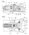
- FIG. 1 is a vertical longitudinal central section through a first embodiment in the driving position and Fig. 2 is a plan view partly. cut along the line II - II in Fig. 1.
- Fig. 3 is a vertical longitudinal central section through this embodiment in a backward fall and
- Fig. 4 is an illustration similar to Fig. 2 when the sole holder is swung out to the side.
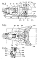
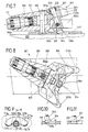
- 5 to 11 show a second embodiment in the vertical longitudinal central section and in section along the line VI-VI in FIG. 5, FIGS. 7 and 8 corresponding to FIGS. 5 and 6 and the position of the individual elements according to play a backward or turning camber.
- FIG. 5a shows a variant of FIG. 5.
- FIGS. 9-11 represent further details of the embodiment according to FIGS. 5 and 6.
- FIGS. 10 and 11 are sections along the line X-X and XI-XI in Fig. 9.
- the toe piece shown in FIGS. 1-4 is designated 101 in its entirety. It has a base plate 119 which is attached to the top 100a of a ski 100 and which carries an axis of rotation 120 running perpendicular to it.
- a housing 102 is mounted on the axis of rotation 120 and contains a release spring 111 with an adjustable preload. This release spring 111 acts on a locking member 121, the elongated hole 121a, which extends in the longitudinal direction of the locking member 121, is penetrated by the axis of rotation 120.
- a sole holder 108 is pivotably mounted on the transverse axis 122.
- the sole holder 108 has on its side facing the housing 102 a recess 108c, in which the locking member 121 engages with its cylindrically rounded end 121b.
- the center of rotation of the axis of rotation 120 is flattened on its front side at 120a, and the elongated hole 121a in the locking member 121 likewise has a flattened portion 121c at one end, which comes into contact with the flattened portion 120a of the axis of rotation 120 in the driving position of the front jaw 101.
- the extent of the flattening 120a of the axis of rotation 120 and the distance a of the plane of symmetry of the locking member 121 from the transverse axis 122 are dimensioned such that the ratio of the triggering torques desired by the designer is achieved in the event of a backward fall and a rotational fall.
- An adjusting screw 103 is screwed into an axially extending threaded bore of the ski-fixed axis of rotation 120, on the head 103a of which the housing 102 is rotatably but secured against axial displacement.
- This adjusting screw 103 makes it possible to adapt the toe 101 to shoe soles of different thicknesses, so that the sole holder 108 fits snugly on the shoe sole and the locking member 121 is supported on the axis of rotation 120 at the same time.
- leg springs 104 Arranged on the transverse axis 122 are two leg springs 104 which endeavor to pivot the sole holder 108 against the locking member 121. This will be the entry of the skier relieved with the ski boot in the toe 101.
- the front jaw 101 In the driving position, the front jaw 101 assumes the position shown in FIGS. 1 and 2.
- the housing 102 which holds the shoe sole laterally with its two legs 102a and 102b, is pivoted about the axis of rotation 120.
- the flattened portion 121 of the elongated hole 121a stands out from the flattened portion 120a of the axis of rotation 120, which likewise results in the trigger spring 111 being compressed.
- the ski boot can leave the toe 101.
- FIGS. 5-8 The second embodiment shown in FIGS. 5-8 is constructed similarly to the first embodiment.
- This front jaw 301 also has a base plate 319 fastened to the upper side 300a of a ski 300, which carries an axis of rotation 320 perpendicular to this plate.
- a housing 302 is mounted on this, in which there is a release spring 311 which can be preloaded.
- This release spring 311 acts on a locking member 321, the slot 321a of which passes through the axis of rotation 320 is and its function is explained in more detail below.
- two legs 302a, 302b are attached to the housing 302, which on the one hand hold the ski boot laterally and which on the other hand serve to receive a transverse axis 322 which runs parallel to the base plate 319.
- the transverse axis 322 is supported in slots 302c, 302d of the two legs 302a, 302b.
- the side walls of the slots 302c, 302d form acute angles ⁇ with the top of the base plate 319.
- a bolt 323 is pivotally mounted on the transverse axis 322, which runs approximately perpendicular to the upper side of the ski 300a in the driving position of the front jaw 301 and whose lower end preferably carries a roller 324 which is guided in a recess 319a in the base plate 319 delimited by a control curve 319b .
- This control curve 319b has a central region 319c which is concave from the direction of the axis of rotation 320 and two convex sections 319d adjoining this region.
- the two convex sections 319d are provided with spatially twisted ramps 319e in their end regions. Since the release spring 311 tends to pivot the bolt 323 clockwise in FIG.
- the roller 324 is always in the driving position the edge of the recess 319a adjacent to the axis of rotation 320 and forming the control curve 319b.
- the underside of the roller 324 is at a distance b from the support plane of the base plate 319, which releases the ski boot in the event of a backward fall of the skier becomes possible.
- An inclination of the bolt 323 is inevitably brought about by the two spatially twisted ramps 319e.
- a sole holder 308 which is under the influence of a compression spring 307, is slidably mounted on the bolt 323.
- This compression spring 307 is located at least with its lower region in a stepped bore 308b of the sole holder 308.
- the displacement path of the sole holder 308 relative to the bolt 323 is limited by an elongated hole 308a penetrated by the transverse axis 322 and penetrated by the transverse axis 322.
- an adjustment of the sole holder 308 to the thickness of different shoe soles is not necessary in the front jaw 301, since this adjustment takes place automatically.
- the ski boot is therefore inserted from above and from behind with its sole under the sole holder 308 and then pivoted towards the upper side 300a of the ski 300, the sole holder 308 taking up its raised position against the pressure of the compression spring 307.
- the housing 302 is first pivoted about the axis of rotation 320.
- the roller 324 comes to one of the ramps 319e of the control cam 319b in the cutout 319a, which results in an oblique position of the bolt 323 and thus of the sole holder 308.
- the locking member 321 is pushed back and the release spring 311 is thereby tensioned somewhat more (FIG. 7).
- the ski boot can therefore leave the toe 301 comfortably in this position. Thereafter, all the elements of the toe 301 are returned to the position shown in FIGS. 5 and 6 by the positive control described.
- FIG. 9 shows a top view of the recess 319a with the control curve 319b according to FIG. 6.
- the spatially twisted ramps 319e provided in the two end regions of the control curve 319b can be seen.
- 10 and 11 are sections along the lines X-X and XI-XI in Fig. 9. From these figures are the distance b of the roller 324 from the support plane of the base plate 319 and the position of the roller 324 on one of the ramps 319e evident.
- FIG. 5a shows a variant of the embodiment according to FIG. 5.
- the compression spring 307 ' is housed in a recess, one half 323'b in the bolt 323' and the other half 308'c in the sole holder 308 'is recessed.
- the displacement of the sole holder 308 'relative to the bolt 323' is limited by an elongated hole 308'a penetrated by the transverse axis 322 'and penetrated by the transverse axis 322'.
- the locking member 321 ' is provided with a spherical end 321'c, which is supported on the outer surface of the cylindrical bolt 323'.
- the invention is not limited to the exemplary embodiments described above and shown in the drawing. Rather, various modifications thereof are possible without leaving the scope of the invention.
- the return of the housing from the pivoted-out position could be supported by springs which urge the sole holder into its central position.
- the compression springs could be designed as disc spring assemblies.
Landscapes
- Footwear And Its Accessory, Manufacturing Method And Apparatuses (AREA)
Applications Claiming Priority (2)
| Application Number | Priority Date | Filing Date | Title |
|---|---|---|---|
| AT0115588A AT391420B (de) | 1988-05-04 | 1988-05-04 | Vorderbacken |
| AT1155/88 | 1988-05-04 |
Publications (3)
| Publication Number | Publication Date |
|---|---|
| EP0340623A2 true EP0340623A2 (fr) | 1989-11-08 |
| EP0340623A3 EP0340623A3 (en) | 1990-09-26 |
| EP0340623B1 EP0340623B1 (fr) | 1992-12-16 |
Family
ID=3507801
Family Applications (1)
| Application Number | Title | Priority Date | Filing Date |
|---|---|---|---|
| EP89107598A Expired - Lifetime EP0340623B1 (fr) | 1988-05-04 | 1989-04-27 | Mâchoires avant |
Country Status (3)
| Country | Link |
|---|---|
| EP (1) | EP0340623B1 (fr) |
| AT (1) | AT391420B (fr) |
| DE (1) | DE58902994D1 (fr) |
Cited By (2)
| Publication number | Priority date | Publication date | Assignee | Title |
|---|---|---|---|---|
| US5566967A (en) * | 1993-02-15 | 1996-10-22 | Htm Sport-Und Freizeitgeraete Aktiengesellschaft | Front jaw for a safety ski binding |
| US20120007338A1 (en) * | 2010-04-12 | 2012-01-12 | Golden Crab S.L. | Automatic release control system for controlling the connection between two elements |
Family Cites Families (5)
| Publication number | Priority date | Publication date | Assignee | Title |
|---|---|---|---|---|
| FR2314742A1 (fr) * | 1975-06-20 | 1977-01-14 | Salomon & Fils F | Fixation de securite pour ski a compensation automatique des contraintes parasites |
| AT361347B (de) * | 1978-04-06 | 1981-03-10 | Tyrolia Freizeitgeraete | Backenkoerper fuer skibindung |
| FR2424037B1 (fr) * | 1978-04-28 | 1982-12-17 | Salomon & Fils F | |
| FR2469189B1 (fr) * | 1979-11-13 | 1985-10-25 | Look Sa | Butee avant de fixation de ski |
| FR2540735A1 (fr) * | 1983-02-14 | 1984-08-17 | Salomon & Fils F | Fixation de securite pour ski |
-
1988
- 1988-05-04 AT AT0115588A patent/AT391420B/de not_active IP Right Cessation
-
1989
- 1989-04-27 EP EP89107598A patent/EP0340623B1/fr not_active Expired - Lifetime
- 1989-04-27 DE DE8989107598T patent/DE58902994D1/de not_active Expired - Lifetime
Cited By (2)
| Publication number | Priority date | Publication date | Assignee | Title |
|---|---|---|---|---|
| US5566967A (en) * | 1993-02-15 | 1996-10-22 | Htm Sport-Und Freizeitgeraete Aktiengesellschaft | Front jaw for a safety ski binding |
| US20120007338A1 (en) * | 2010-04-12 | 2012-01-12 | Golden Crab S.L. | Automatic release control system for controlling the connection between two elements |
Also Published As
| Publication number | Publication date |
|---|---|
| AT391420B (de) | 1990-10-10 |
| EP0340623A3 (en) | 1990-09-26 |
| EP0340623B1 (fr) | 1992-12-16 |
| DE58902994D1 (de) | 1993-01-28 |
| ATA115588A (de) | 1990-04-15 |
Similar Documents
| Publication | Publication Date | Title |
|---|---|---|
| DE3310739C2 (fr) | ||
| AT397923B (de) | Sicherheitsskibindung | |
| EP3702005B1 (fr) | Talonnière | |
| DE1428866B2 (de) | Auslösende Fersenabstütz vorrichtung für Skibindungen | |
| DE1960002B2 (de) | Auslösende Skibindung mit einer verschwenkbaren Trittplatte | |
| DE2608131A1 (de) | Schiausloesebindung | |
| EP0365861B1 (fr) | Front jaw | |
| DE2926822A1 (de) | Bindungsanordnung fuer ski | |
| AT392594B (de) | Backenkoerper fuer sicherheitsskibindungen | |
| EP0259407B1 (fr) | Fixation de securite pour ski | |
| DE2163296B2 (de) | Auslösebindung für Skier | |
| EP0217322A2 (fr) | Fixation de sécurité pour ski | |
| AT526533A4 (de) | Ferseneinheit für eine Tourenskibindung und Tourenskibindung | |
| DE69000206T2 (de) | Sicherheitsskibindung. | |
| EP0061590B1 (fr) | Frein de ski | |
| EP0340623B1 (fr) | Mâchoires avant | |
| CH653560A5 (de) | Mit einer skibremse kombinierter fersenhalter. | |
| DE3151222C2 (de) | Vorderbacken für eine Sicherheits-Skibindung | |
| EP0257244A2 (fr) | Fixation de ski de sécurité, notamment mâchoire avant | |
| EP0189562A1 (fr) | Talonnière pour fixation de ski | |
| EP0250809A2 (fr) | Mâchoires avant de fixation de sécurité pour ski | |
| EP0426050A2 (fr) | Butée avant | |
| EP0389757A1 (fr) | Butée avant | |
| EP0547531B1 (fr) | Machoire avant | |
| EP0415006B1 (fr) | Mâchoire avant |
Legal Events
| Date | Code | Title | Description |
|---|---|---|---|
| PUAI | Public reference made under article 153(3) epc to a published international application that has entered the european phase |
Free format text: ORIGINAL CODE: 0009012 |
|
| AK | Designated contracting states |
Kind code of ref document: A2 Designated state(s): CH DE FR LI |
|
| PUAL | Search report despatched |
Free format text: ORIGINAL CODE: 0009013 |
|
| AK | Designated contracting states |
Kind code of ref document: A3 Designated state(s): CH DE FR LI |
|
| 17P | Request for examination filed |
Effective date: 19910121 |
|
| RAP1 | Party data changed (applicant data changed or rights of an application transferred) |
Owner name: TMC CORPORATION |
|
| 17Q | First examination report despatched |
Effective date: 19920416 |
|
| GRAA | (expected) grant |
Free format text: ORIGINAL CODE: 0009210 |
|
| RAP1 | Party data changed (applicant data changed or rights of an application transferred) |
Owner name: HTM SPORT- UND FREIZEITGERAETE GESELLSCHAFT M.B.H. |
|
| AK | Designated contracting states |
Kind code of ref document: B1 Designated state(s): CH DE FR LI |
|
| REF | Corresponds to: |
Ref document number: 58902994 Country of ref document: DE Date of ref document: 19930128 |
|
| PG25 | Lapsed in a contracting state [announced via postgrant information from national office to epo] |
Ref country code: DE Effective date: 19930211 |
|
| ET | Fr: translation filed | ||
| PG25 | Lapsed in a contracting state [announced via postgrant information from national office to epo] |
Ref country code: LI Effective date: 19930430 Ref country code: CH Effective date: 19930430 |
|
| PLBE | No opposition filed within time limit |
Free format text: ORIGINAL CODE: 0009261 |
|
| STAA | Information on the status of an ep patent application or granted ep patent |
Free format text: STATUS: NO OPPOSITION FILED WITHIN TIME LIMIT |
|
| 26N | No opposition filed | ||
| PG25 | Lapsed in a contracting state [announced via postgrant information from national office to epo] |
Ref country code: FR Effective date: 19931229 |
|
| REG | Reference to a national code |
Ref country code: CH Ref legal event code: PL |
|
| REG | Reference to a national code |
Ref country code: FR Ref legal event code: ST |